 Lapsed, fee not paid8 drawings
Medical Devices · US 9,877,775 B2
Electrosurgical instrument with a knife blade stop
An electrosurgical forceps is provided with a shaft that extends from a housing of the electrosurgical forceps.
US 9,877,782 B2 · Assignee: Ethicon LLC · Inventors: Voegele; Aaron C. et al.
Sheet 1 of 19 from the published document. All sheets in the USPTO PDF
An end effector for operating on tissue comprises an upper jaw, a lower jaw, a flexible member, and a pair of conductive members. The upper jaw and the lower jaw are configured to receive tissue when in an open position and the upper jaw is movable toward the lower jaw. The flexible member is coupled to either the upper jaw or the lower jaw, and is configured to deform in response to compression of tissue between the jaws. One of the conductive members is associated with the flexible member and is configured to move with the flexible member in response to compression of tissue between the jaws. The end effector may be configured to manipulate the position of muscle within tissue in response to compression of tissue between the jaws.
A variety of surgical instruments include a tissue cutting element and one or more elements that transmit radio frequency (RF) energy to tissue (e.g., to coagulate or seal the tissue). An example of such an electrosurgical instrument is the ENSEAL® Tissue Sealing Device by Ethicon Endo-Surgery, Inc., of Cincinnati, Ohio. Further examples of such devices and related concepts are disclosed in U.S. Pat. No. 6,500,176 entitled “Electrosurgical Systems and Techniques for Sealing Tissue,” issued Dec. 31, 2002, the disclosure of which is incorporated by reference herein; U.S. Pat. No. 7,112,201 entitled “Electrosurgical Instrument and Method of Use,” issued Sep. 26, 2006, the disclosure of which is incorporated by reference herein; U.S. Pat. No. 7,125,409, entitled “Electrosurgical Working End for Controlled Energy Delivery,” issued Oct. 24, 2006, the disclosure of which is incorporated by refe
1 of 19 drawing sheets so far from the published document, cropped to the drawing. Every sheet is in the USPTO PDF.
What the patent claimed, word for word. All of it is now free to use.
A variety of surgical instruments include a tissue cutting element and one or more elements that transmit radio frequency (RF) energy to tissue (e.g., to coagulate or seal the tissue). An example of such an electrosurgical instrument is the ENSEAL® Tissue Sealing Device by Ethicon Endo-Surgery, Inc., of Cincinnati, Ohio. Further examples of such devices and related concepts are disclosed in U.S. Pat. No. 6,500,176 entitled “Electrosurgical Systems and Techniques for Sealing Tissue,” issued Dec. 31, 2002, the disclosure of which is incorporated by reference herein; U.S. Pat. No. 7,112,201 entitled “Electrosurgical Instrument and Method of Use,” issued Sep. 26, 2006, the disclosure of which is incorporated by reference herein; U.S. Pat. No. 7,125,409, entitled “Electrosurgical Working End for Controlled Energy Delivery,” issued Oct. 24, 2006, the disclosure of which is incorporated by reference herein; U.S. Pat. No. 7,169,146 entitled “Electrosurgical Probe and Method of Use,” issued Jan. 30, 2007, the disclosure of which is incorporated by reference herein; U.S. Pat. No. 7,186,253, entitled “Electrosurgical Jaw Structure for Controlled Energy Delivery,” issued Mar. 6, 2007, the disclosure of which is incorporated by reference herein; U.S. Pat. No. 7,189,233, entitled “Electrosurgical Instrument,” issued Mar. 13, 2007, the disclosure of which is incorporated by reference herein; U.S. Pat. No. 7,220,951, entitled “Surgical Sealing Surfaces and Methods of Use,” issued May 22, 2007, the disclosure of which is incorporated by reference herein; U.S. Pat. No. 7,309,849, entitled “Polymer Compositions Exhibiting a PTC Property and Methods of Fabrication,” issued Dec. 18, 2007, the disclosure of which is incorporated by reference herein; U.S. Pat. No. 7,311,709, entitled “Electrosurgical Instrument and Method of Use,” issued Dec. 25, 2007, the disclosure of which is incorporated by reference herein; U.S. Pat. No. 7,354,440, entitled “Electrosurgical Instrument and Method of Use,” issued Apr. 8, 2008, the disclosure of which is incorporated by reference herein; U.S. Pat. No. 7,381,209, entitled “Electrosurgical Instrument,” issued Jun. 3, 2008, the disclosure of which is incorporated by reference herein.
Additional examples of electrosurgical cutting instruments and related concepts are disclosed in U.S. Pub. No. 2011/0087218, entitled “Surgical Instrument Comprising First and Second Drive Systems Actuatable by a Common Trigger Mechanism,” published Apr. 14, 2011, now U.S. Pat. No. 8,939,974, issued on Jan. 27, 2015, the disclosure of which is incorporated by reference herein; U.S. Pub. No. 2012/0083783, entitled “Surgical Instrument with Jaw Member,” published Apr. 5, 2012, now U.S. Pat. No. 8,888,809, issued on Nov. 18, 2014, the disclosure of which is incorporated by reference herein; U.S. Pub. No. 2012/0116379, entitled “Motor Driven Electrosurgical Device with Mechanical and Electrical Feedback,” published May 10, 2012, now U.S. Pat. No. 9,161,803, issued on Oct. 20, 2015, the disclosure of which is incorporated by reference herein; U.S. Pub. No. 2012/0078243, entitled “Control Features for Articulating Surgical Device,” published Mar. 29, 2012, the disclosure of which is incorporated by reference herein; U.S. Pub. No. 2012/0078247, entitled “Articulation Joint Features for Articulating Surgical Device,” published Mar. 29, 2012, now U.S. Pat. No. 9,402,682, issued on Aug. 2, 2016, the disclosure of which is incorporated by reference herein; U.S. Pub. No. 2013/0030428, entitled “Surgical Instrument with Multi-Phase Trigger Bias,” published Jan. 31, 2013, now U.S. Pat. No. 9,089,327, issued on Jul. 28, 2015, the disclosure of which is incorporated by reference herein; and U.S. Pub. No. 2013/0023868, entitled “Surgical Instrument with Contained Dual Helix Actuator Assembly,” published Jan. 31, 2013, now U.S. Pat. No. 9,545,253, issued Jan. 17, 2017, the disclosure of which is incorporated by reference herein.
While a variety of surgical instruments have been made and used, it is believed that no one prior to the inventors has made or used the invention described in the appended claims.
While the specification concludes with claims which particularly point out and distinctly claim this technology, it is believed this technology will be better understood from the following description of certain examples taken in conjunction with the accompanying drawings, in which like reference numerals identify the same elements and in which:
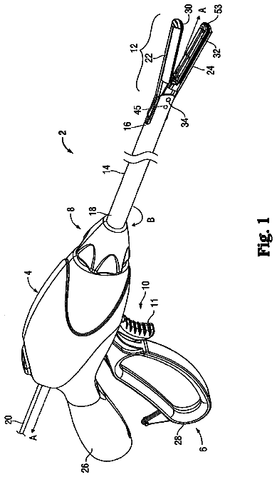
FIG. 1 depicts a side elevational view of an exemplary electrosurgical medical instrument;
FIG. 2 depicts a perspective view of the end effector of the instrument of FIG. 1 , in an open configuration;
FIG. 3 depicts another perspective view of the end effector of the instrument of FIG. 1 , in an open configuration;
FIG. 4 depicts a cross-sectional end view of the end effector of FIG. 2 , in a closed configuration and with the blade in a distal position;
FIG. 5 depicts a partial perspective view of the distal end of an exemplary alternative firing beam suitable for incorporation in the instrument of FIG. 1 ;
FIG. 6 depicts a perspective view of an exemplary alternative end effector suitable for use in the instrument of FIG. 1 , in a closed position;
FIG. 7 depicts a perspective view of the end effector of FIG. 6 in an open position;
FIG. 8 depicts a cross-sectional perspective view of the end effector of FIG. 6 , taken along line 8 - 8 of FIG. 6 ;
FIG. 9 depicts a cross-sectional perspective view of the end effector of FIG. 6 , taken along line 9 - 9 of FIG. 7 ;
FIG. 10 depicts a front perspective view of an exemplary spring electrode pad;
FIG. 11 depicts a front elevational view of the spring electrode pad of FIG. 10 ;
FIG. 12 depicts a rear perspective view of the spring electrode pad of FIG. 10 ;
FIG. 13 depicts a front perspective view of an exemplary alternative spring electrode pad;
FIG. 14 depicts a front elevational view of the spring electrode pad of FIG. 13 ;
FIG. 15 depicts a rear perspective view of the spring electrode pad of FIG. 13 ;
FIG. 16A depicts a cross-sectional view of the end effector of FIG. 6 having the spring electrode pad of FIG. 10 lightly closed about tissue, taken along line 9 - 9 of FIG. 7 ;
FIG. 16B depicts a cross-sectional view of the end effector of FIG. 6 having the spring electrode pad of FIG. 10 fully clamped about tissue, taken along line 8 - 8 of FIG. 6 ;
FIG. 17A depicts a cross-sectional view of the end effector of FIG. 6 having the spring electrode pad of FIG. 13 in a convex orientation lightly clamped about tissue, taken along line 9 - 9 of FIG. 7 ;
FIG. 17B depicts a cross-sectional view of the end effector of FIG. 6 having the spring electrode pad of FIG. 13 in a flat orientation fully clamped about tissue, taken along line 8 - 8 of FIG. 6 ;
FIG. 18A depicts a cross-sectional view of the end effector of FIG. 6 having the spring electrode pad of FIG. 13 in a concave orientation lightly closed about tissue, taken along line 9 - 9 of FIG. 7 ;
FIG. 18B depicts a cross-sectional view of the end effector of FIG. 6 having the spring electrode pad of FIG. 13 in a flat orientation fully clamped about tissue, taken along line 8 - 8 of FIG. 6 ;
FIG. 19 depicts a perspective view of another exemplary alternative end effector in a closed position;
FIG. 20 depicts a perspective view of the end effector of FIG. 19 in an open position;
FIG. 21 depicts an exploded perspective view of the lower jaw of the end effector of FIG. 19 ;
FIG. 22 depicts a perspective view of another exemplary alternative end effector in a closed position;
FIG. 23A depicts a cross-sectional view of the end effector of FIG. 22 having an exemplary insulator lightly closed about tissue, taken along line 23 - 23 of FIG. 22 ;
FIG. 23B depicts a cross-sectional view of the end effector of FIG. 22 having the insulator of FIG. 23A fully clamped about tissue, taken along line 23 - 23 of FIG. 22 ;
FIG. 24A depicts a cross-sectional view of the end effector of FIG. 22 having another exemplary insulator lightly closed about tissue, taken along line 23 - 23 of FIG. 22 ; and
FIG. 24B depicts a cross-sectional view of the end effector of FIG. 22 having the insulator of FIG. 24A fully clamped about tissue, taken along line 23 - 23 of FIG. 22 .
The drawings are not intended to be limiting in any way, and it is contemplated that various embodiments of the technology may be carried out in a variety of other ways, including those not necessarily depicted in the drawings. The accompanying drawings incorporated in and forming a part of the specification illustrate several aspects of the present technology, and together with the description serve to explain the principles of the technology; it being understood, however, that this technology is not limited to the precise arrangements shown.
The following description of certain examples of the technology should not be used to limit its scope. Other examples, features, aspects, embodiments, and advantages of the technology will become apparent to those skilled in the art from the following description, which is by way of illustration, one of the best modes contemplated for carrying out the technology. As will be realized, the technology described herein is capable of other different and obvious aspects, all without departing from the technology. Accordingly, the drawings and descriptions should be regarded as illustrative in nature and not restrictive.
It is further understood that any one or more of the teachings, expressions, embodiments, examples, etc. described herein may be combined with any one or more of the other teachings, expressions, embodiments, examples, etc. that are described herein. The following-described teachings, expressions, embodiments, examples, etc. should therefore not be viewed in isolation relative to each other. Various suitable ways in which the teachings herein may be combined will be readily apparent to those of ordinary skill in the art in view of the teachings herein. Such modifications and variations are intended to be included within the scope of the claims.
For clarity of disclosure, the terms “proximal” and “distal” are defined herein relative to a surgeon or other operator grasping a surgical instrument having a distal surgical end effector. The term “proximal” refers the position of an element closer to the surgeon or other operator and the term “distal” refers to the position of an element closer to the surgical end effector of the surgical instrument and further away from the surgeon or other operator.
I. Exemplary Electrosurgical Device with Articulation Feature
FIGS. 1-4 show an exemplary electrosurgical instrument ( 10 ) that is constructed and operable in accordance with at least some of the teachings of U.S. Pat. Nos. 6,500,176; 7,112,201; 7,125,409; 7,169,146; 7,186,253; 7,189,233; 7,220,951; 7,309,849; 7,311,709; 7,354,440; 7,381,209; U.S. Pub. No. 2011/0087218, now U.S. Pat. No. 8,939,974, issued Jan. 27, 2015; U.S. Pub. No. 2012/0083783, now U.S. Pat. No. 8,888,809, issued Nov. 18, 2014; U.S. Pub. No. 2012/0116379, now U.S. Pat. No. 9,161,803, issued Oct. 20, 2015; U.S. Pub. No. 2012/0078243; U.S. Pub. No. 2012/0078247, now U.S. Pat. No. 9,402,682, issued Aug. 2, 2016; U.S. Pub. No. 2013/0030428, now U.S. Pat. No. 9,089,327, issued on Jul. 28, 2015; and/or U.S. Pub. No. 2013/0023868, now U.S. Pat. No. 9,545,253, issued Jan. 17, 2017. As described therein and as will be described in greater detail below, electrosurgical instrument ( 10 ) is operable to cut tissue and seal or weld tissue (e.g., a blood vessel, etc.) substantially simultaneously. In other words, electrosurgical instrument ( 10 ) operates similar to an endocutter type of stapler, except that electrosurgical instrument ( 10 ) provides tissue welding through application of bipolar RF energy instead of providing lines of staples to join tissue. It should also be understood that electrosurgical instrument ( 10 ) may have various structural and functional similarities with the ENSEAL® Tissue Sealing Device by Ethicon Endo-Surgery, Inc., of Cincinnati, Ohio. Furthermore, electrosurgical instrument ( 10 ) may have various structural and functional similarities with the devices taught in any of the other references that are cited and incorporated by reference herein. To the extent that there is some degree of overlap between the teachings of the references cited herein, the ENSEAL® Tissue Sealing Device by Ethicon Endo-Surgery, Inc., of Cincinnati, Ohio, and the following teachings relating to electrosurgical instrument ( 10 ), there is no intent for any of the description herein to be presumed as admitted prior art. Several teachings below will in fact go beyond the scope of the teachings of the references cited herein and the ENSEAL® Tissue Sealing Device by Ethicon Endo-Surgery, Inc., of Cincinnati, Ohio.
A. Exemplary Handpiece and Shaft
Electrosurgical instrument ( 10 ) of the present example includes a handpiece ( 20 ), a shaft ( 30 ) extending distally from handpiece ( 20 ), and an end effector ( 40 ) disposed at a distal end of shaft ( 30 ). Handpiece ( 20 ) of the present example includes a pistol grip ( 22 ), a pivoting trigger ( 24 ), an activation button ( 26 ), and an articulation control ( 28 ). Trigger ( 24 ) is pivotable toward and away from pistol grip ( 22 ) to selectively actuate end effector ( 40 ) as will be described in greater detail below. Activation button ( 26 ) is operable to selectively activate RF circuitry that is in communication with end effector ( 40 ), as will also be described in greater detail below. In some versions, activation button ( 26 ) also serves as a mechanical lockout against trigger ( 24 ), such that trigger ( 24 ) cannot be fully actuated unless button ( 26 ) is being pressed simultaneously. Examples of how such a lockout may be provided are disclosed in one or more of the references cited herein. In addition or in the alternative, trigger ( 24 ) may serve as an electrical and/or mechanical lockout against button ( 26 ), such that button ( 26 ) cannot be effectively activated unless trigger ( 24 ) is being squeezed simultaneously. It should be understood that pistol grip ( 22 ), trigger ( 24 ), and button ( 26 ) may be modified, substituted, supplemented, etc. in any suitable way, and that the descriptions of such components herein are merely illustrative.
Shaft ( 30 ) of the present example includes a rigid outer sheath ( 32 ) and an articulation section ( 36 ). Articulation section ( 36 ) is operable to selectively laterally deflect end effector ( 40 ) at various angles relative to the longitudinal axis defined by sheath ( 32 ). In some versions, articulation section ( 36 ) and/or some other portion of outer sheath ( 32 ) includes a flexible outer sheath (e.g., a heat shrink tube, etc.) disposed about its exterior. Articulation section ( 36 ) of shaft ( 30 ) may take a variety of forms. By way of example only, articulation section ( 36 ) may be configured in accordance with one or more teachings of U.S. Pub. No. 2012/0078247, now U.S. Pat. No. 9,402,682, issued on Aug. 2, 2016, the disclosure of which is incorporated by reference herein. As another merely illustrative example, articulation section ( 36 ) may be configured in accordance with one or more teachings of U.S. Pub. No. 2012/0078248, entitled “Articulation Joint Features for Articulating Surgical Device,” published Mar. 29, 2012, now U.S. Pat. No. 9,220,559, issued on Dec. 29, 2015, the disclosure of which is incorporated by reference herein. Various other suitable forms that articulation section ( 36 ) may take will be apparent to those of ordinary skill in the art in view of the teachings herein. It should also be understood that some versions of instrument ( 10 ) may simply lack articulation section ( 36 ).
In some versions, shaft ( 30 ) is also rotatable about the longitudinal axis defined by sheath ( 32 ), relative to handpiece ( 20 ), via a knob ( 34 ). Such rotation may provide rotation of end effector ( 40 ) and shaft ( 30 ) unitarily. In some other versions, knob ( 34 ) is operable to rotate end effector ( 40 ) without rotating articulation section ( 36 ) or any portion of shaft ( 30 ) that is proximal of articulation section ( 36 ). As another merely illustrative example, electrosurgical instrument ( 10 ) may include one rotation control that provides rotatability of shaft ( 30 ) and end effector ( 40 ) as a single unit; and another rotation control that provides rotatability of end effector ( 40 ) without rotating articulation section ( 36 ) or any portion of shaft ( 30 ) that is proximal of articulation section ( 36 ). Other suitable rotation schemes will be apparent to those of ordinary skill in the art in view of the teachings herein. Of course, rotatable features may simply be omitted if desired.
Articulation control ( 28 ) of the present example is operable to selectively control articulation section ( 36 ) of shaft ( 30 ), to thereby selectively laterally deflect end effector ( 40 ) at various angles relative to the longitudinal axis defined by shaft ( 30 ). While articulation control ( 28 ) is in the form of a rotary dial in the present example, it should be understood that articulation control ( 28 ) may take numerous other forms. By way of example only, some merely illustrative forms that articulation control ( 28 ) and other components of handpiece ( 20 ) may take are disclosed in U.S. Pub. No. 2012/0078243, the disclosure of which is incorporated by reference herein; in U.S. Pub. No. 2012/0078244, entitled “Control Features for Articulating Surgical Device,” published Mar. 29, 2012, the disclosure of which is incorporated by reference herein; and in U.S. Pub. No. 2013/0023868, now U.S. Pat. No. 9,545,253, issued on Jan. 17, 2017, the disclosure of which is incorporated by reference herein. Still other suitable forms that articulation control ( 28 ) may take will be apparent to those of ordinary skill in the art in view of the teachings herein. It should also be understood that some versions of instrument ( 10 ) may simply lack an articulation control ( 28 ).
B. Exemplary End Effector
End effector ( 40 ) of the present example comprises a first jaw ( 42 ) and a second jaw ( 44 ). In the present example, first jaw ( 42 ) is substantially fixed relative to shaft ( 30 ); while second jaw ( 44 ) pivots relative to shaft ( 30 ), toward and away from first jaw ( 42 ). Use of the term “pivot” should not be read as necessarily requiring pivotal movement about a fixed axis. In some versions, second jaw ( 44 ) pivots about an axis that is defined by a pin (or similar feature) that slides along an elongate slot or channel as second jaw ( 44 ) moves toward first jaw ( 42 ). In such versions, the pivot axis translates along the path defined by the slot or channel while second jaw ( 44 ) simultaneously pivots about that axis. It should be understood that such sliding/translating pivotal movement is encompassed within terms such as “pivot,” “pivots,” “pivotal,” “pivotable,” “pivoting,” and the like. Of course, some versions may provide pivotal movement of second jaw ( 44 ) about an axis that remains fixed and does not translate within a slot or channel, etc.
In some versions, actuators such as rods or cables, etc., may extend through sheath ( 32 ) and be joined with second jaw ( 44 ) at a pivotal coupling ( 43 ), such that longitudinal movement of the actuator rods/cables/etc. through shaft ( 30 ) provides pivoting of second jaw ( 44 ) relative to shaft ( 30 ) and relative to first jaw ( 42 ). Of course, jaws ( 42 , 44 ) may instead have any other suitable kind of movement and may be actuated in any other suitable fashion. By way of example only, and as will be described in greater detail below, jaws ( 42 , 44 ) may be actuated and thus closed by longitudinal translation of a firing beam ( 60 ), such that actuator rods/cables/etc. may simply be eliminated in some versions.
As best seen in FIGS. 2-4 , first jaw ( 42 ) defines a longitudinally extending elongate slot ( 46 ); while second jaw ( 44 ) also defines a longitudinally extending elongate slot ( 48 ). In addition, the top side of first jaw ( 42 ) presents a first electrode surface ( 50 ); while the underside of second jaw ( 44 ) presents a second electrode surface ( 52 ). Electrode surfaces ( 50 , 52 ) are in communication with an electrical source ( 80 ) via one or more conductors (not shown) that extend along the length of shaft ( 30 ). These conductors are coupled with electrical source ( 80 ) and a controller ( 82 ) via a cable ( 84 ), which extends proximally from handpiece ( 20 ). Electrical source ( 80 ) is operable to deliver RF energy to first electrode surface ( 50 ) at a first polarity and to second electrode surface ( 52 ) at a second (opposite) polarity, such that RF current flows between electrode surfaces ( 50 , 52 ) and thereby through tissue captured between jaws ( 42 , 44 ). In some versions, firing beam ( 60 ) serves as an electrical conductor that cooperates with electrode surfaces ( 50 , 52 ) (e.g., as a ground return) for delivery of bipolar RF energy captured between jaws ( 42 , 44 ). Electrical source ( 80 ) may be external to electrosurgical instrument ( 10 ) or may be integral with electrosurgical instrument ( 10 ) (e.g., in handpiece ( 20 ), etc.), as described in one or more references cited herein or otherwise. A controller ( 82 ) regulates delivery of power from electrical source ( 80 ) to electrode surfaces ( 50 , 52 ). Controller ( 82 ) may also be external to electrosurgical instrument ( 10 ) or may be integral with electrosurgical instrument ( 10 ) (e.g., in handpiece ( 20 ), etc.), as described in one or more references cited herein or otherwise. It should also be understood that electrode surfaces ( 50 , 52 ) may be provided in a variety of alternative locations, configurations, and relationships.
By way of example only, power source ( 80 ) and/or controller ( 82 ) may be configured in accordance with at least some of the teachings of U.S. Provisional Pat. App. No. 61/550,768, entitled “Medical Instrument,” filed Oct. 24, 2011, the disclosure of which is incorporated by reference herein; U.S. Pub. No. 2011/0082486, entitled “Devices and Techniques for Cutting and Coagulating Tissue,” published Apr. 7, 2011, now U.S. Pat. No. 9,089,360, issued on Jul. 28, 2015, the disclosure of which is incorporated by reference herein; U.S. Pub. No. 2011/0087212, entitled “Surgical Generator for Ultrasonic and Electrosurgical Devices,” published Apr. 14, 2011, now U.S. Pat. No. 8,986,302, issued on Mar. 24, 2015, the disclosure of which is incorporated by reference herein; U.S. Pub. No. 2011/0087213, entitled “Surgical Generator for Ultrasonic and Electrosurgical Devices,” published Apr. 14, 2011, now U.S. Pat. No. 8,951,248, issued on Feb. 10, 2015, the disclosure of which is incorporated by reference herein; U.S. Pub. No. 2011/0087214, entitled “Surgical Generator for Ultrasonic and Electrosurgical Devices,” published Apr. 14, 2011, now U.S. Pat. No. 9,039,695, issued on May 26, 2015, the disclosure of which is incorporated by reference herein; U.S. Pub. No. 2011/0087215, entitled “Surgical Generator for Ultrasonic and Electrosurgical Devices,” published Apr. 14, 2011, now U.S. Pat. No. 9,050,093, issued on Jun. 9, 2015, the disclosure of which is incorporated by reference herein; U.S. Pub. No. 2011/0087216, entitled “Surgical Generator for Ultrasonic and Electrosurgical Devices,” published Apr. 14, 2011, now U.S. Pat. No. 8,956,349, issued on Feb. 17, 2015, the disclosure of which is incorporated by reference herein; and/or U.S. Pub. No. 2011/0087217, entitled “Surgical Generator for Ultrasonic and Electrosurgical Devices,” published Apr. 14, 2011, now U.S. Pat. No. 9,060,776, issued on Jun. 23, 2015, the disclosure of which is incorporated by reference herein. Other suitable configurations for power source ( 80 ) and controller ( 82 ) will be apparent to those of ordinary skill in the art in view of the teachings herein.
As best seen in FIG. 4 , the lower side of first jaw ( 42 ) includes a longitudinally extending recess ( 58 ) adjacent to slot ( 46 ); while the upper side of second jaw ( 44 ) includes a longitudinally extending recess ( 59 ) adjacent to slot ( 48 ). FIG. 2 shows the upper side of first jaw ( 42 ) including a plurality of teeth serrations ( 46 ). It should be understood that the lower side of second jaw ( 44 ) may include complementary serrations that nest with serrations ( 46 ), to enhance gripping of tissue captured between jaws ( 42 , 44 ) without necessarily tearing the tissue. In other words, it should be understood that serrations may be generally blunt or otherwise atraumatic. FIG. 3 shows an example of serrations ( 46 ) in first jaw ( 42 ) as mainly recesses; with serrations ( 48 ) in second jaw ( 44 ) as mainly protrusions. Of course, serrations ( 46 , 48 ) may take any other suitable form or may be simply omitted altogether. It should also be understood that serrations ( 46 , 48 ) may be formed of an electrically non-conductive, or insulative, material, such as plastic, glass, and/or ceramic, for example, and may include a treatment such as polytetrafluoroethylene, a lubricant, or some other treatment to substantially prevent tissue from getting stuck to jaws ( 42 , 44 ).
With jaws ( 42 , 44 ) in a closed position, shaft ( 30 ) and end effector ( 40 ) are sized and configured to fit through trocars having various inner diameters, such that electrosurgical instrument ( 10 ) is usable in minimally invasive surgery, though of course electrosurgical instrument ( 10 ) could also be used in open procedures if desired. By way of example only, with jaws ( 42 , 44 ) in a closed position, shaft ( 30 ) and end effector ( 40 ) may present an outer diameter of approximately 5 mm. Alternatively, shaft ( 30 ) and end effector ( 40 ) may present any other suitable outer diameter (e.g., between approximately 2 mm and approximately 20 mm, etc.).
As another merely illustrative variation, either jaw ( 42 , 44 ) or both of jaws ( 42 , 44 ) may include at least one port, passageway, conduit, and/or other feature that is operable to draw steam, smoke, and/or other gases/vapors/etc. from the surgical site. Such a feature may be in communication with a source of suction, such as an external source or a source within handpiece ( 20 ), etc. In addition, end effector ( 40 ) may include one or more tissue cooling features (not shown) that reduce the degree or extent of thermal spread caused by end effector ( 40 ) on adjacent tissue when electrode surfaces ( 50 , 52 ) are activated. Various suitable forms that such cooling features may take will be apparent to those of ordinary skill in the art in view of the teachings herein.
In some versions, end effector ( 40 ) includes one or more sensors (not shown) that are configured to sense a variety of parameters at end effector ( 40 ), including but not limited to temperature of adjacent tissue, electrical resistance or impedance of adjacent tissue, voltage across adjacent tissue, forces exerted on jaws ( 42 , 44 ) by adjacent tissue, etc. By way of example only, end effector ( 40 ) may include one or more positive temperature coefficient (PTC) thermistor bodies ( 54 , 56 ) (e.g., PTC polymer, etc.), located adjacent to electrodes ( 50 , 52 ) and/or elsewhere. Data from sensors may be communicated to controller ( 82 ). Controller ( 82 ) may process such data in a variety of ways. By way of example only, controller ( 82 ) may modulate or otherwise change the RF energy being delivered to electrode surfaces ( 50 , 52 ), based at least in part on data acquired from one or more sensors at end effector ( 40 ). In addition or in the alternative, controller ( 82 ) may alert the user to one or more conditions via an audio and/or visual feedback device (e.g., speaker, lights, display screen, etc.), based at least in part on data acquired from one or more sensors at end effector ( 40 ). It should also be understood that some kinds of sensors need not necessarily be in communication with controller ( 82 ), and may simply provide a purely localized effect at end effector ( 40 ). For instance, a PTC thermistor bodies ( 54 , 56 ) at end effector ( 40 ) may automatically reduce the energy delivery at electrode surfaces ( 50 , 52 ) as the temperature of the tissue and/or end effector ( 40 ) increases, thereby reducing the likelihood of overheating. In some such versions, a PTC thermistor element is in series with power source ( 80 ) and electrode surface ( 50 , 52 ); and the PTC thermistor provides an increased impedance (reducing flow of current) in response to temperatures exceeding a threshold. Furthermore, it should be understood that electrode surfaces ( 50 , 52 ) may be used as sensors (e.g., to sense tissue impedance, etc.). Various kinds of sensors that may be incorporated into electrosurgical instrument ( 10 ) will be apparent to those of ordinary skill in the art in view of the teachings herein. Similarly various things that can be done with data from sensors, by controller ( 82 ) or otherwise, will be apparent to those of ordinary skill in the art in view of the teachings herein. Other suitable variations for end effector ( 40 ) will also be apparent to those of ordinary skill in the art in view of the teachings herein.
C. Exemplary Firing Beam
As also seen in FIGS. 2-4 , electrosurgical instrument ( 10 ) of the present example includes a firing beam ( 60 ) that is longitudinally movable along part of the length of end effector ( 40 ). Firing beam ( 60 ) is coaxially positioned within shaft ( 30 ), extends along the length of shaft ( 30 ), and translates longitudinally within shaft ( 30 ) (including articulation section ( 36 ) in the present example), though it should be understood that firing beam ( 60 ) and shaft ( 30 ) may have any other suitable relationship. In some versions, a proximal end of firing beam ( 60 ) is secured to a firing tube or other structure within shaft ( 30 ); and the firing tube or other structure extends through the remainder of shaft ( 30 ) to handpiece ( 20 ) where it is driven by movement of trigger ( 24 ). Firing beam ( 60 ) includes a sharp distal blade ( 64 ), an upper flange ( 62 ), and a lower flange ( 66 ). As best seen in FIG. 4 , distal blade ( 64 ) extends through slots ( 46 , 48 ) of jaws ( 42 , 44 ), with upper flange ( 62 ) being located above jaw ( 44 ) in recess ( 59 ) and lower flange ( 66 ) being located below jaw ( 42 ) in recess ( 58 ). The configuration of distal blade ( 64 ) and flanges ( 62 , 66 ) provides an “I-beam” type of cross section at the distal end of firing beam ( 60 ). While flanges ( 62 , 66 ) extend longitudinally only along a small portion of the length of firing beam ( 60 ) in the present example, it should be understood that flanges ( 62 , 66 ) may extend longitudinally along any suitable length of firing beam ( 60 ). In addition, while flanges ( 62 , 66 ) are positioned along the exterior of jaws ( 42 , 44 ), flanges ( 62 , 66 ) may alternatively be disposed in corresponding slots formed within jaws ( 42 , 44 ). For instance, each jaw ( 42 , 44 ) may define a “T”-shaped slot, with parts of distal blade ( 64 ) being disposed in one vertical portion of each “T”-shaped slot and with flanges ( 62 , 66 ) being disposed in the horizontal portions of the “T”-shaped slots. Various other suitable configurations and relationships will be apparent to those of ordinary skill in the art in view of the teachings herein.
Distal blade ( 64 ) is substantially sharp, such that distal blade ( 64 ) will readily sever tissue that is captured between jaws ( 42 , 44 ). Distal blade ( 64 ) is also electrically grounded in the present example, providing a return path for RF energy as described elsewhere herein. In some other versions, distal blade ( 64 ) serves as an active electrode. In addition or in the alternative, distal blade ( 64 ) may be selectively energized with ultrasonic energy (e.g., harmonic vibrations at approximately 55.5 kHz, etc.).
The “I-beam” type of configuration of firing beam ( 60 ) provides closure of jaws ( 42 , 44 ) as firing beam ( 60 ) is advanced distally. In particular, flange ( 62 ) urges jaw ( 44 ) pivotally toward jaw ( 42 ) as firing beam ( 60 ) is advanced from a proximal position ( FIGS. 1-3 ) to a distal position ( FIG. 4 ), by bearing against recess ( 59 ) formed in jaw ( 44 ). This closing effect on jaws ( 42 , 44 ) by firing beam ( 60 ) may occur before distal blade ( 64 ) reaches tissue captured between jaws ( 42 , 44 ). Such staging of encounters by firing beam ( 60 ) may reduce the force required to squeeze trigger ( 24 ) to actuate firing beam ( 60 ) through a full firing stroke. In other words, in some such versions, firing beam ( 60 ) may have already overcome an initial resistance required to substantially close jaws ( 42 , 44 ) on tissue before encountering resistance from severing the tissue captured between jaws ( 42 , 44 ). Of course, any other suitable staging may be provided.
In the present example, flange ( 62 ) is configured to cam against a ramp feature at the proximal end of jaw ( 44 ) to open jaw ( 44 ) when firing beam ( 60 ) is retracted to a proximal position and to hold jaw ( 44 ) open when firing beam ( 60 ) remains at the proximal position. This camming capability may facilitate use of end effector ( 40 ) to separate layers of tissue, to perform blunt dissections, etc., by forcing jaws ( 42 , 44 ) apart from a closed position. In some other versions, jaws ( 42 , 44 ) are resiliently biased to an open position by a spring or other type of resilient feature. While jaws ( 42 , 44 ) close or open as firing beam ( 60 ) is translated in the present example, it should be understood that other versions may provide independent movement of jaws ( 42 , 44 ) and firing beam ( 60 ). By way of example only, one or more cables, rods, beams, or other features may extend through shaft ( 30 ) to selectively actuate jaws ( 42 , 44 ) independently of firing beam ( 60 ). Such jaw ( 42 , 44 ) actuation features may be separately controlled by a dedicated feature of handpiece ( 20 ). Alternatively, such jaw actuation features may be controlled by trigger ( 24 ) in addition to having trigger ( 24 ) control firing beam ( 60 ). It should also be understood that firing beam ( 60 ) may be resiliently biased to a proximal position, such that firing beam ( 60 ) retracts proximally when a user relaxes their grip on trigger ( 24 ).
FIG. 5 shows an exemplary alternative firing beam ( 70 ), which may be readily substituted for firing beam ( 60 ). In this example, firing beam ( 70 ) comprises a blade insert ( 94 ) that is interposed between two beam plates ( 90 , 92 ). Blade insert ( 94 ) includes a sharp distal edge ( 96 ), such that blade insert ( 94 ) will readily sever tissue that is captured between jaws ( 42 , 44 ). Sharp distal edge ( 96 ) is exposed by a proximally extending recess ( 93 ) formed in plates ( 90 , 92 ). A set of pins ( 72 , 74 , 76 ) are transversely disposed in plates ( 90 , 92 ). Pins ( 72 , 74 ) together effectively serve as substitutes for upper flange ( 62 ); while pin ( 76 ) effectively serves as a substitute for lower flange ( 66 ). Thus, pins ( 72 , 74 ) bear against channel ( 59 ) of jaw ( 44 ), and pin ( 76 ) bears against channel ( 58 ) of jaw ( 42 ), as firing beam ( 70 ) is translated distally through slots ( 46 , 48 ). Pins ( 72 , 74 , 76 ) of the present example are further configured to rotate within plates ( 90 , 92 ), about the axes respectively defined by pins ( 72 , 74 , 76 ). It should be understood that such rotatability of pins ( 72 , 74 , 76 ) may provide reduced friction with jaws ( 42 , 44 ), thereby reducing the force required to translate firing beam ( 70 ) distally and proximally in jaws ( 42 , 44 ). Pin ( 72 ) is disposed in an angled elongate slot ( 98 ) formed through plates ( 90 , 92 ), such that pin ( 72 ) is translatable along slot ( 98 ). In particular, pin ( 72 ) is disposed in the proximal portion of slot ( 98 ) as firing beam ( 70 ) is being translated distally. When firing beam ( 70 ) is translated proximally, pin ( 72 ) slides distally and upwardly in slot ( 98 ), increasing the vertical separation between pins ( 72 , 76 ), which in turn reduces the compressive forces applied by jaws ( 42 , 44 ) and thereby reduces the force required to retract firing beam ( 70 ). Of course, firing beam ( 70 ) may have any other suitable configuration. By way of example only, firing beam ( 70 ) may be configured in accordance with at least some of the teachings of U.S. Pub. No. 2012/0083783, now U.S. Pat. No. 8,888,809, issued Nov. 18, 2014, the disclosure of which is incorporated by reference herein.
D. Exemplary Operation
In an exemplary use, end effector ( 40 ) is inserted into a patient via a trocar. Articulation section ( 36 ) is substantially straight when end effector ( 40 ) and part of shaft ( 30 ) are inserted through the trocar. Articulation control ( 28 ) may then be manipulated to pivot or flex articulation section ( 36 ) of shaft ( 30 ) in order to position end effector ( 40 ) at a desired position and orientation relative to an anatomical structure within the patient. Two layers of tissue of the anatomical structure are then captured between jaws ( 42 , 44 ) by squeezing trigger ( 24 ) toward pistol grip ( 22 ). Such layers of tissue may be part of the same natural lumen defining anatomical structure (e.g., blood vessel, portion of gastrointestinal tract, portion of reproductive system, etc.) in a patient. For instance, one tissue layer may comprise the top portion of a blood vessel while the other tissue layer may comprise the bottom portion of the blood vessel, along the same region of length of the blood vessel (e.g., such that the fluid path through the blood vessel before use of electrosurgical instrument ( 10 ) is perpendicular to the longitudinal axis defined by end effector ( 40 ), etc.). In other words, the lengths of jaws ( 42 , 44 ) may be oriented perpendicular to (or at least generally transverse to) the length of the blood vessel. As noted above, flanges ( 62 , 66 ) cammingly act to pivot jaw ( 42 ) toward jaw ( 44 ) when firing beam ( 60 ) is actuated distally by squeezing trigger ( 24 ) toward pistol grip ( 22 ). Jaws ( 42 , 44 ) may be substantially clamping tissue before trigger ( 24 ) has swept through a full range of motion toward pistol grip ( 22 ), such that trigger ( 24 ) may continue pivoting toward pistol grip ( 22 ) through a subsequent range of motion after jaws ( 42 , 44 ) have substantially clamped on the tissue.
The description continues in the full USPTO document.
About 6,957 words. The USPTO PDF has it with every drawing.
Fees are due 3.5, 7.5 and 11.5 years after grant. This patent expired on January 30, 2026, so the fee marked "not paid" was the one that went unpaid.
ELECTROSURGICAL INSTRUMENT END EFFECTOR WITH COMPLIANT ELECTRODE
Filed Mar 2013 · published Sep 2014Electrosurgical instrument end effector with compliant electrode
Filed Mar 2013 · granted Jan 2018Earlier publications, parents and continuations. None of them can still be enforced, or this patent would not be listed.
Prior art cited by the examiner or applicant. Useful when you check your own idea for novelty.
Everything on this page comes from the documents linked above.