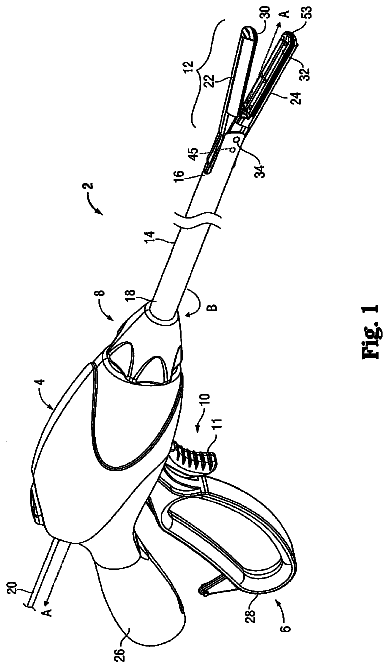
The present disclosure is related generally to electrosurgical devices with various mechanisms for clamping and treating tissue. In particular, the present disclosure is related to electrosurgical devices with simultaneous I-beam and spring driven cam jaw closure mechanism.
Conventional electrosurgical devices have poor grasping and cannot seal without cutting. These issues are due to the fact that the I-beam closes the jaws. Due to component tolerances it is almost impossible to make a set of large jaws that can be closed with an I-beam where the jaws will come fully together with the I-beam closing from the rear of the jaws. The I-beam, however, has lots of advantages on sealing thick and diseased tissue. So, a solution is needed that allows for improved grasping and sealing without cutting, but also allows the jaws to be closed with an I-beam.
While several devices have been made and used, it is believed that no one prior to the inventors has made or used the device described in the appended claims.
Cross-reference to related applications
This application is related to U.S. patent application Ser. No. 14/468,037, titled “LOCKOUT DISABLING MECHANISM,” filed Aug. 25, 2014, now U.S. Pub. No. 2016/0051317 and U.S. patent application Ser. No. 14/467,990, titled “ELECTROSURGICAL ELECTRODE MECHANISM,” filed Aug. 25, 2014, now U.S. Pub. No. 2016/0051316; each of which is incorporated herein by reference in its entirety.
Summary
In one embodiment, a surgical instrument is provided. The surgical instrument comprises an end effector and a handle assembly. The end effector comprises a movable jaw; and a cutting element slidably movable within the end effector. The handle assembly comprises an energy button configured to deliver energy to at least one electrode located in the end effector; a trigger plate operably coupled to a jaw closure mechanism. The trigger plate configured to close the movable jaw; a firing plate operably coupled to a cutting element drive mechanism. The firing plate is configured to drive the cutting element independently of the jaw closure mechanism. The cutting element drive mechanism is configured to close the movable jaw when the cutting element is driven. The handle assembly also comprises a trigger operatively coupled to the trigger plate and the firing plate. The jaw closure mechanism and the cutting element drive mechanism are configured to simultaneously close the movable jaw.
In another embodiment, the surgical instrument comprises a spring located inline with the jaw closure mechanism, wherein the jaw closure mechanism is configured to close the jaw ahead of the cutting element drive system until a force required to close the movable jaw overcomes a force generated by the spring at which time the cutting element drive mechanism overtakes the jaw closure mechanism to close the movable jaw. In another embodiment, the spring can be pre-compressed to increase the starting load. In another embodiment, the jaw closure mechanism comprises a spring, a closure bar coupled to the spring, and a pivoting link having a proximal end and a distal end, the proximal end coupled to the closure bar and the distal end coupled to the movable jaw. In another embodiment, the surgical instrument comprises a closure actuator coupled to the spring and coupled to the trigger plate via a toggle clamp, wherein the closure actuator is configured to compress the spring.
In another embodiment, the cutting element drive mechanism comprises a firing bar having a proximal end and a distal end, a cutting element coupled to the distal end of the firing bar, a rack coupled to the proximal end of the firing bar, wherein the rack is operatively coupled to the firing plate.
In another embodiment, the surgical instrument comprises a lockout disabling mechanism comprising a lock arm operatively coupled to a lever arm and a lockout element, wherein the lockout element is configured to prevent the cutting element drive mechanism from driving a cutting element.
In one embodiment, a surgical instrument is provided. The surgical instrument comprises an end effector comprising a movable jaw, a cutting element slidably movable within the end effector, a jaw closure mechanism configured to close the movable jaw via a spring driven cam system, and a cutting element drive mechanism configured to drive the cutting element independently of the jaw closure mechanism. The cutting element drive system comprises an I-beam member. The cutting element drive mechanism is configured to close the movable jaw when the cutting element is driven. The jaw closure mechanism and the cutting element drive mechanism are configured to simultaneously close the movable jaw.
In another embodiment, the jaw closure mechanism is configured to close the jaw ahead of the cutting element drive system until a force required to close the movable jaw overcomes a force generated by the spring at which time the cutting element drive mechanism overtakes the jaw closure mechanism to close the movable jaw.
In another embodiment, the spring can be pre-compressed to increase the starting load.
In another embodiment the jaw closure mechanism comprises a closure bar coupled to the spring and a pivoting link having a proximal end and a distal end, the proximal end coupled to the closure bar and the distal end coupled to the movable jaw.
In another embodiment, the surgical instrument comprises a closure actuator having a proximal end and a distal end, the distal end coupled to the spring and the proximal end coupled to a toggle clamp configured to drive the closure actuator. The closure actuator is configured to compress the spring when the closure actuator moves in a distal direction.
In another embodiment, the cutting element drive mechanism comprises a firing bar having a proximal end and a distal end, a cutting element coupled to the distal end of the firing bar, and a rack coupled to the proximal end of the firing bar. The rack is operatively coupled to the firing plate.
In another embodiment, the surgical instrument comprises a lockout disabling mechanism comprising a lock arm operatively coupled to a lever arm and a lockout element. The lockout element is configured to prevent the cutting element drive mechanism from driving a cutting element.
In one embodiment, a surgical instrument is provided. The surgical instrument comprises a handle assembly, a shaft assembly, and an end effector. The handle assembly comprises a trigger operatively coupled to a trigger plate and a firing plate, an energy button configured to deliver energy to at least one electrode, a lockout element operatively coupled to the energy button. The lockout element is configured to prevent operation of the firing plate. The handle assembly also comprises a lockout disabling mechanism configured to disable the lockout element. The lockout disabling mechanism is operable between a first position and a second position. When the lockout disabling mechanism is located in the first position, the lockout element is enabled and can be unlocked by the energy button, and wherein when the lockout disabling mechanism is in the second position, the lockout element is disabled. The shaft assembly comprises a proximal end and a distal end. The shaft assembly is coupled to the handle assembly at the proximal end. The end effector is coupled to the distal end of the shaft assembly. The end effector comprises a jaw assembly, comprising a first jaw member and a second jaw member. The rotation of the trigger plate transitions the jaw assembly between an open configuration and an approximated configuration by moving at least one of the first jaw member and the second jaw member relative to the other one of the first jaw member and the second jaw member. The end effector also comprises a cutting element deployable in response to rotation of the firing plate, a jaw closure mechanism configured to close the movable jaw via a spring driven cam system, and a cutting element drive mechanism configured to drive the cutting element independently of the jaw closure mechanism. The cutting element drive system comprises an I-beam member. The cutting element drive mechanism is configured to close the movable jaw when the cutting element is driven. The jaw closure mechanism and the cutting element drive mechanism are configured to simultaneously close the at least one of the first jaw member and the second jaw member.
In another embodiment, the jaw closure mechanism is configured to close the jaw ahead of the cutting element drive system until a force required to close the at least one of the first jaw member and the second jaw member overcomes a force generated by the spring at which time the cutting element drive mechanism overtakes the jaw closure mechanism to close the at least one of the first jaw member and the second jaw member.
In another embodiment, the spring can be pre-compressed to increase the starting load.
In another embodiment, the jaw closure mechanism comprises a closure bar coupled to the spring and a pivoting link having a proximal end and a distal end, the proximal end coupled to the closure bar and the distal end coupled to the at least one of the first jaw member and the second jaw member.
In another embodiment, the surgical instrument comprises a closure actuator having a proximal end and a distal end, the distal end coupled to the spring and the proximal end coupled to a toggle clamp configured to drive the closure actuator, wherein the closure actuator is configured to compress the spring when the closure actuator moves in a distal direction.
In another embodiment, the cutting element drive mechanism comprises a firing bar having a proximal end and a distal end a cutting element coupled to the distal end of the firing bar and a rack coupled to the proximal end of the firing bar. The rack is operatively coupled to the firing plate.
The foregoing summary is illustrative only and is not intended to be in any way limiting. In addition to the illustrative aspects, embodiments, and features described above, further aspects, embodiments, and features will become apparent by reference to the drawings and the following detailed description.
Figures
The novel features of the embodiments described herein are set forth with particularity in the appended claims. The embodiments, however, both as to organization and methods of operation may be better understood by reference to the following description, taken in conjunction with the accompanying drawings as follows.
FIG. 1 illustrates a surgical instrument comprising a knife lockout disabling mechanism, according to one embodiment.
FIG. 2 is a perspective view of a handle assembly of the surgical instrument illustrated in FIG. 1 with the left handle housing shroud and several sheaths in the shaft assembly removed, according to one embodiment.
FIG. 3 is a side elevation view of a handle assembly of a surgical instrument, similar to the surgical instrument shown in FIGS. 1 and 2 , with the left handle housing shroud removed, and without the lockout disabling mechanism, according to one embodiment.
FIG. 4 is an exploded view of the shaft assembly, end effector, yoke, and rack portions of the surgical instrument shown in FIGS. 1 and 2 , according to one embodiment.
FIG. 5 is a perspective view of the shaft assembly, end effector, yoke, and rack shown in FIG. 4 in the assembled state, according to one embodiment.
FIG. 6 is a perspective view of the shaft assembly, end effector, yoke, and rack shown in FIG. 5 , according to one embodiment, with the electrically insulative nonconductive tube removed to show the functional components of the shaft assembly in the assembled state.
FIG. 7 is a sectional view taken along a longitudinal axis of the shaft assembly, yoke, and rack shown in FIG. 5 , according to one embodiment, to show the functional components of the shaft assembly in the assembled state.
FIG. 8 is partial perspective view of the shaft assembly shown in FIG. 7 , according to one embodiment.
FIG. 9 is a side view of an end effector portion of the surgical instrument shown in FIGS. 1 and 2 with the jaws open, according to one embodiment.
FIG. 10 shows the closure bar and I-beam member at the initial stage of clamp closure and firing sequence where the I-beam member is located at the base of a ramp in the upper jaw, according to one embodiment.
FIG. 11 shows the closure bar and I-beam member further advanced distally than shown in FIG. 10 , where the I-beam member is located at an intermediate position along the ramp in the upper jaw, according to one embodiment.
FIG. 12 shows the closure bar and I-beam member further advanced distally than shown in FIG. 11 where the I-beam member is located at the top of the ramp in the upper jaw, according to one embodiment.
FIG. 13 shows the closure bar and I-beam member further advanced distally than shown in FIG. 12 , where the I-beam member is located past the ramp in the upper jaw, according to one embodiment.
FIG. 14 is a side elevational view of the surgical instrument shown in FIGS. 1 and 2 with the left housing shroud removed, shaft assembly sheaths removed, and the jaw fully open, according to one embodiment.
FIG. 15 is a perspective view of the surgical instrument shown in FIG. 14 with the right housing shroud removed, according to one embodiment.
FIG. 16 is another perspective view of the surgical instrument shown in FIG. 15 , according to one embodiment.
FIG. 17 is a side elevational view of the surgical instrument shown in FIG. 14 with the right housing shroud removed, according to one embodiment.
FIG. 18 is a side elevational view of the surgical instrument shown in FIG. 14 with the firing plate removed, according to one embodiment.
FIG. 19 is a side elevational view of the surgical instrument shown in FIG. 18 with the lockout defeat mechanism slider removed, according to one embodiment.
FIG. 20 is a side elevational view of the surgical instrument shown in FIG. 18 with the toggle clamp and yoke removed, according to one embodiment.
FIG. 21 is a partial perspective view of the surgical instrument shown in FIG. 20 , according to one embodiment.
FIG. 22 is a partial perspective view of the surgical instrument shown in FIG. 21 with the firing plate replaced, according to one embodiment.
FIG. 23 is a partial perspective view of the surgical instrument shown in FIG. 22 with the lockout defeat mechanism slider, lever arm, and lock arm removed, according to one embodiment.
FIG. 24 is a side elevational view of the surgical instrument shown in FIGS. 1 and 2 with the left and right housing shrouds removed, shaft assembly sheaths removed, jaws clamped, and the lockout defeat mechanism enabled, e.g., in the “ON” position, according to one embodiment.
FIG. 25 is a side elevational view of the surgical instrument shown in FIGS. 1 and 2 with the left and right housing shrouds removed, shaft assembly sheaths removed, jaws fully closed, knife fully fired, and the lockout defeat mechanism disabled, e.g., in the “OFF” position, according to one embodiment.
FIG. 26 is a side elevational view of the surgical instrument shown in FIGS. 1 and 2 with the left and right housing shrouds removed, shaft assembly sheaths removed, jaws fully open, knife not fired, and the lockout defeat mechanism disabled, e.g., in the “OFF” position, according to one embodiment.
Description
In the following detailed description, reference is made to the accompanying drawings, which form a part hereof. In the drawings, similar symbols and reference characters typically identify similar components throughout the several views, unless context dictates otherwise. The illustrative embodiments described in the detailed description, drawings, and claims are not meant to be limiting. Other embodiments may be utilized, and other changes may be made, without departing from the scope of the subject matter presented here.
The following description of certain examples of the technology should not be used to limit its scope. Other examples, features, aspects, embodiments, and advantages of the technology will become apparent to those skilled in the art from the following description, which is by way of illustration, one of the best modes contemplated for carrying out the technology. As will be realized, the technology described herein is capable of other different and obvious aspects, all without departing from the technology. Accordingly, the drawings and descriptions should be regarded as illustrative in nature and not restrictive.
It is further understood that any one or more of the teachings, expressions, embodiments, examples, etc. described herein may be combined with any one or more of the other teachings, expressions, embodiments, examples, etc. that are described herein. The following-described teachings, expressions, embodiments, examples, etc. should therefore not be viewed in isolation relative to each other. Various suitable ways in which the teachings herein may be combined will be readily apparent to those of ordinary skill in the art in view of the teachings herein. Such modifications and variations are intended to be included within the scope of the claims.
Before explaining the various embodiments of the surgical devices having a closure system comprising an I-beam and spring driven cam system to simultaneously close a set of opposing jaws in detail, it should be noted that the various embodiments disclosed herein are not limited in their application or use to the details of construction and arrangement of parts illustrated in the accompanying drawings and description. Rather, the disclosed embodiments may be positioned or incorporated in other embodiments, variations and modifications thereof, and may be practiced or carried out in various ways. Accordingly, embodiments of the surgical devices disclosed herein are illustrative in nature and are not meant to limit the scope or application thereof. Furthermore, unless otherwise indicated, the terms and expressions employed herein have been chosen for the purpose of describing the embodiments for the convenience of the reader and are not to limit the scope thereof. In addition, it should be understood that any one or more of the disclosed embodiments, expressions of embodiments, and/or examples thereof, can be combined with any one or more of the other disclosed embodiments, expressions of embodiments, and/or examples thereof, without limitation.
Also, in the following description, it is to be understood that terms such as front, back, inside, outside, top, bottom and the like are words of convenience and are not to be construed as limiting terms. Terminology used herein is not meant to be limiting insofar as devices described herein, or portions thereof, may be attached or utilized in other orientations. The various embodiments will be described in more detail with reference to the drawings.
In various embodiments, the present disclosure provides an electrosurgical instrument having a closure system comprising an I-beam and spring driven cam system to simultaneously close a set of opposing jaws. In order to grasp better a separate mechanism is provided to close the jaws independently of the I-beam drive. To ensure the I-beam will also be able to close the jaws the separate mechanism operates in tandem with the I-beam drive. In one embodiment, a cam closure that closes the jaws and moves along with the I-beam is provided. Some conventional electrosurgical devices employ a toggle clamp to move the I-beam to close the jaws. A separate closure system can be attached to the toggle clamp alongside the I-beam so that they both move at the same time. The cam closure can be timed to close the jaws before the I-beam. The cam system also can incorporate an inline spring. This spring can compress at the end of the closure stroke to keep the jaws shut with a set spring force. If material in the jaws forces the spring to compress too much on the cam closure then the I-beam can take over to close the jaws. Accordingly, in this system the I-beam will ensure the jaws always fully close the jaws with the toggle clamp. The I-beam is configured to only close the jaws when the material in the jaws takes more force to close than the cam spring can provide. The cam system also can have a rising mechanical advantage as the jaw is closed such that the further the spring is compressed the less force is exerted on the jaws. This prevents damaging tissue from too much spring force.
In one embodiment, the closure system comprising an I-beam and spring driven cam system to simultaneously close a set of opposing jaws can be configured to operate in the following manner:
place tissue in the jaws and pull the trigger;
the toggle clamp pushes on the I-beam and the cam closure;
the cam immediately pushes on the jaw through a spring to close it, the I-beam trails a closure ramp on the upper jaw;
the cam fully closes the jaws before the toggle stops moving;
the toggle clamp continues to move (e.g., another 0.05 inches) to compress the closure spring to ensure the jaws are sprung closed, the I-beam moves over the top of the ramp; and
thick tissue in the jaws may compress the spring on the cam closure before the end of the toggle stroke, the I-beam will hit the closure ramp and force the jaws closed to ensure that the I-beam will repeatedly be located over the ramp with the jaws closed before the toggle stops moving.
The closure system comprising an I-beam and spring cam driven cam system is configured to simultaneously close a set of opposing jaws provides several advantages over conventional devices. The disclosed device can seal tissue without necessarily cutting the tissue, provides improved tissue grasping, ensures that the I-beam is located over the ramp before a gear train in the jaw device takes over to provide lower force to fire. The disclosed closure system also provides improved jaw opening and tissue dissection over conventional devices. The disclosed closure system also provides lower force to fire from preload on tissue. The gears fire the I-beam forward and can be configured to operate with conventional electrosurgical jaw designs. Additional advantages, not necessarily described herein, are also provided.
In various embodiments, the present disclosure provides an electrosurgical radio frequency (RF) bipolar sealing device comprising an I-beam and spring driven cam system to simultaneously close a set of opposing jaws. The spring driven cam closure system can close the jaws first unless the force to close the jaws overcomes the spring, at this point the I-beam will close the jaws. The cam system composes a spring connected to a bar, which is in turn connected to a pivoting link, which is then connected to a jaw. Pushing on the spring pushes on the bar which pushes on the link which closes the jaw. The spring on the cam closure system can be pre-compressed to raise its starting load.
Turning now to the figures, FIG. 1 illustrates a surgical instrument 102 comprising a trigger assembly 107 and a closure system arrangement for closing the jaws 110 comprising a separate spring driven cam closure mechanism that is independent of the I-beam closure mechanism. The spring driven cam closure system and the I-beam closure system are configured to independently close a set of opposing jaws 116 a , 116 b , and independently fire a cutting element in the end effector 110 . The trigger assembly 107 is configured to clamp and independently fire an end effector 110 coupled to the shaft assembly 112 of the surgical instrument 102 . In the embodiment shown in FIG. 1 , the surgical instrument comprises a trigger assembly 107 and a lockout disabling mechanism 108 . In this view, a first jaw member 116 a of an end effector 110 is fully open and the knife lockout disabling mechanism 108 is located in the off position. The knife lockout disabling mechanism 108 is configured to clamp and fire an end effector 110 coupled to the surgical instrument 102 . The surgical instrument 102 comprises a handle assembly 104 , a shaft assembly 112 , and the end effector 110 . The shaft assembly 112 comprises a proximal end and a distal end. The proximal end of the shaft assembly 112 is coupled to the distal end of the handle assembly 104 . The end effector 110 is coupled to the distal end of the shaft assembly 112 . The handle assembly 104 comprises a pistol grip 118 . The handle assembly 104 comprises a left handle housing shroud 106 a and a right handle housing shroud 106 b . The trigger assembly 107 comprises a trigger 109 actuatable towards the pistol grip 118 . The knife lockout disabling mechanism 108 comprises a button 139 , or knob, that is actuatable for adjusting or controlling the position of the knife lockout disabling mechanism 108 between first and second positions A and B (A=Distal and B=Proximal relative to the clinician) within a slot 111 formed in the left handle housing shroud 106 a . A rotatable shaft knob 120 is configured to rotate the shaft assembly 112 with respect to the handle assembly 104 . The handle assembly 104 further comprises an energy button 122 configured to provide electrosurgical energy to one or more electrodes in the end effector 110 .
The knife lockout mechanism forces the user to first clamp (close the jaws 110 ), energize the electrodes, then cut the tissue (fire the knife). The knife unlock feature contains the energy button 122 so that the energy button 122 has to be depressed before the knife can be released or that the single trigger can move the rack 136 forward. The single trigger 109 closes the jaws in the first ˜13 degrees of stroke. The single trigger 109 fires the knife in the last ˜29 degrees of stroke. The lockout is the stop in between the first stroke and the second stroke. An energy switch (not shown) is located underneath the energy button 122 housing. Accordingly, the lock release mechanism also is the energy delivery element.
The shaft assembly 112 comprises a closure/jaw actuator, a firing/cutting member actuator, and an outer sheath. In some embodiments, the outer sheath comprises the closure actuator. The outer sheath comprises one or more contact electrodes on a distal end configured to interface with the end effector 110 . The one or more contact electrodes are operatively coupled to the energy button 122 and an energy source (not shown).
The energy source may be suitable for therapeutic tissue treatment, tissue cauterization/sealing, as well as sub-therapeutic treatment and measurement. The energy button 122 controls the delivery of energy to the electrodes. As used throughout this disclosure, a button refers to a switch mechanism for controlling some aspect of a machine or a process. The buttons may be made out of a hard material such as usually plastic or metal. The surface may be formed or shaped to accommodate the human finger or hand, so as to be easily depressed or pushed. Buttons can be most often biased switches, even though many un-biased buttons (due to their physical nature) require a spring to return to their un-pushed state. Terms for the “pushing” of the button, may include press, depress, mash, and punch.
In some embodiments, an end effector 110 is coupled to the distal end of the shaft assembly 112 . The end effector 110 comprises a first jaw member 116 a and a second jaw member 116 b . The first jaw member 116 a is pivotally coupled to the second jaw member 116 b . The first jaw member 116 a is pivotally moveable with respect to the second jaw member 116 b to grasp tissue therebetween. In some embodiments, the second jaw member 116 b is fixed. In other embodiments, the first jaw member 116 a and the second jaw member 116 b are pivotally movable. The end effector 110 comprises at least one electrode. The electrode is configured to deliver energy. Energy delivered by the electrode may comprise, for example, radiofrequency (RF) energy, sub-therapeutic RF energy, ultrasonic energy, and/or other suitable forms of energy. In some embodiments, a cutting member (not shown) is receivable within a longitudinal slot defined by the first jaw member 116 a and/or the second jaw member 116 b . The cutting member is configured to cut tissue grasped between the first jaw member 116 a and the second jaw member 116 b . In some embodiments, the cutting member comprises an electrode for delivering energy, such as, for example, RF and/or ultrasonic energy.
In certain instances, as described above, the surgical instrument 102 may include an automatic energy lockout mechanism. The energy lockout mechanism can be associated with a closure mechanism of the surgical instrument 102 . In certain instances, the energy lockout mechanism can be configured to permit energy delivery to the end effector 10 when the energy delivery button 122 is actuated if the jaw members 116 a and 116 b are in an open configuration. In certain instances, the energy lockout mechanism may be configured to deny energy delivery to the end effector 110 when the energy delivery button 122 is actuated if the jaw members 116 a and 116 b are in a closed configuration. In certain instances, the energy lockout mechanism automatically transitions from permitting the energy delivery to denying the energy delivery when the jaw members 116 a and 116 b are transitioned from the closed configuration to the open configuration, for example. In certain instances, the energy lockout mechanism automatically transitions from denying the energy delivery to permitting the energy delivery when the jaw members 116 a and 116 b are transitioned from the open configuration to the closed configuration, for example.
FIG. 2 is a perspective view of a handle assembly 104 of a surgical instrument 102 illustrated in FIG. 1 , according to one embodiment, with the right housing shroud 106 a and the outer and inner sheaths of the shaft assembly 112 removed to show some of the internal mechanisms. The left handle housing shroud 106 b of the handle assembly 104 comprises the knife lockout disabling mechanism 108 . The button 139 is located in the first “off” position A (A=distal relative to the clinician) within the slot 111 formed in the right handle housing shroud 106 a . In the illustrated embodiment, position B (B=proximal relative to the clinician) corresponds to the second “on” position of the knife lockout disabling mechanism 108 , where the knife lockout mechanism remains disabled until the button is switched back to position A. Accordingly, position A corresponds to the enabled state of the knife lockout mechanism and position B corresponds to the disabled state of the knife lockout mechanism. Stated differently, position A corresponds to the “off” state of the knife lockout disabling mechanism 108 and position B corresponds to the “on” state of the knife lockout disabling mechanism 108 . When the knife lockout mechanism is in the disabled state, the energy button 122 may appear to be depressed to provide a visual indication to the clinician that the knife lockout mechanism has been disabled but without energizing the electrodes in the end effector 110 ( FIG. 1 ). When the knife lockout mechanism is disabled, the knife may be fired at will without the need to apply electrosurgical energy to one or more electrodes in the end effector 110 .
The trigger assembly 107 comprises the necessary components for closing the jaw members 116 a , 116 b and firing the cutting member or knife bands 174 . The trigger assembly 107 comprises a trigger plate 124 and firing plate 128 operatively coupled to the trigger 109 . Squeezing the trigger 109 in direction C towards the pistol grip 118 rotates the trigger plate 124 which operates the toggle clamp 145 to advance a yoke 132 and a closure actuator 129 distally to close the jaw members 116 a , 116 b of the end effector. Initial rotation of the trigger plate 124 also slightly rotates the firing plate 128 . The firing plate 128 comprises a sector gear with a plurality of teeth 131 that engage and rotate a first pinion gear 133 , which engages a second pinion gear 134 to advance a rack 136 (neither is shown in this view). A lock arm 157 (shown in FIGS. 21-22 , for example) is operatively coupled to a lever arm 115 , an unlock arm 119 , and a lockout element 165 . When the instrument 102 is in normal lockout mode, the lock arm 157 engages a notch 158 (shown in FIGS. 4 and 21-23 , for example) in the rack 136 to lock the rack 136 and prevent the rack 136 from moving distally (firing) no matter how hard the trigger 109 is squeezed.
The single trigger 109 closes the jaws in the first ˜13 degrees of stroke. The trigger plate 124 is configured to interface with the trigger plate 124 during rotation of the trigger 109 from an initial position to a first rotation, which is ˜13 degrees of stroke, for example. The trigger plate 124 is operably coupled to the firing plate 128 . In certain instances, the firing plate 128 may include a first slot 128 a and a second slot 128 b . The first slot 128 a receives a drive pin 148 fixedly coupled to the trigger plate 124 . The pin 148 slidably moves within the first slot 128 a . Rotation of the trigger plate 124 , while the pin 148 is slidably received within the first slot 128 a , drives rotation of the firing plate 128 . The teeth 131 of the sector gear engage and rotate the first pinion 133 , which in turn drives the second pinion 134 , which drives the rack 136 distally to fire the cutting element, or knife, but only when the knife lockout is unlocked, released, or disabled.
The single trigger 109 fires the knife in the last ˜29 degrees of stroke. Rotation of the trigger plate 124 beyond a predetermined rotation such as, for example, the first rotation, causes rotation of the firing plate 128 . Rotation of the firing plate 128 deploys a cutting member within the end effector 110 . For example, in the illustrated embodiment, the firing plate 128 comprises a sector gear operably coupled to a rack 136 through the first and second pinions 133 , 134 . The firing plate 128 comprises a plurality of teeth 131 configured to interface with the first pinion 133 . Rotation of the firing plate 128 rotates the first and second pinions 133 , 134 , to drive the rack 136 distally. Distal movement of the rack 136 drives the cutting member actuator distally, causing deployment of the cutting member (e.g., knife) within the end effector 110 .
The lockout is the stop in between the first stroke and the second stroke. Turning back now to the description of the lockout disabling mechanism 108 , when the slider 113 button 139 portion is in located in position A, the lock arm 157 cam be released by pressing or actuating the energy button 122 to rotate the lockout element 165 , which rotates the unlock arm 119 to release the lock arm 157 . Once the lock arm 157 is released, the rack 136 is enabled to advance distally and fire the knife by squeezing the trigger 109 in direction C further towards the pistol grip 118 . As the trigger 109 is squeezed, the firing plate 128 rotates and drives the first pinion gear 133 , which drives the second pinion gear 134 to drive the rack 136 .
When the button 139 is located in position B, the slider 113 rotates the lever arm 115 , which rotates the unlock arm 119 to releases the lock arm 157 . While the button 139 is in position B, the rack 136 can be fired without the need to press energy button 122 to rotate the lockout element 165 . A detent may be provided to hold the button in either position A or B. These and other features are described in more detail hereinbelow.
The shaft assembly 112 comprises a closure/jaw actuator and a firing/cutting member actuator. The closure/jaw actuator comprises a yoke 132 and toggle clamp 145 assembly operatively coupled to a closure actuator 129 which acts on a closure spring 114 coupled to a spring-to-bar interface element 127 and a closure bar 142 . In one instance the closure bar 142 is operatively coupled to the jaw members 116 a , 116 b via at least one linkage. The firing/cutting member actuator comprises a rack 136 operatively coupled to a firing bar 117 , which is slidably received within the closure actuator 129 and the closure spring 114 . The firing bar 117 is coupled to a knife pusher block 140 and a flexible I-beam knife band 174 comprising multiple flexible bands fastened together and a cutting element at the distal end. Advancing the rack 136 in the distal direction advances the cutting element band 174 distally through a channel or slot formed in the jaw members 116 a , 116 b.
FIG. 3 is a side elevation view of a handle assembly 104 of a surgical instrument 101 , with the left handle housing shroud 106 a removed to expose various mechanisms located within the handle assembly 104 and without the knife lockout disabling mechanism 108 , according to one embodiment. Except for the knife lockout disabling mechanism, in other aspects, the surgical instrument 101 operates in a manner similar to the surgical instrument described in connection with FIGS. 1 and 2 .
FIG. 4 is an exploded view of the shaft assembly 112 , end effector 110 , yoke 132 , and rack 136 portions of the surgical instrument 102 shown in FIGS. 1 and 2 , according to one embodiment. FIG. 5 is a perspective view of the shaft assembly 112 , end effector 110 , yoke 132 , and rack 136 shown in FIG. 4 in the assembled state, according to one embodiment. FIG. 6 is a perspective view of the shaft assembly 112 , end effector 110 , yoke 132 , and rack 136 shown in FIG. 5 , according to one embodiment, with the electrically insulative nonconductive tube 176 removed to show the functional components of the shaft assembly 112 in the assembled state. FIG. 7 is a sectional view taken along a longitudinal axis of the shaft assembly 112 , yoke 132 , and rack 136 shown in FIG. 5 , according to one embodiment, to show the functional components of the shaft assembly 112 in the assembled state. FIG. 8 is partial perspective view of the shaft assembly 112 shown in FIG. 7 , according to one embodiment.
The description continues in the full USPTO document.
 Lapsed, fee not paid16 drawings