Lapsed, fee not paid4 drawings
Medical Devices · US 9,877,743 B2
Circular surgical scalpel and marker
Disclosed herein are devices useful for marking and making circular incisions in surgeries particularly breast surgeries.
US 9,877,775 B2 · Assignee: COVIDIEN LP · Inventors: Hart; Keir
Sheet 1 of 8 from the published document. All sheets in the USPTO PDF
An electrosurgical forceps is provided with a shaft that extends from a housing of the electrosurgical forceps. An end effector assembly operably coupled to a distal end of the shaft includes a pair of first and second jaw members having proximal and distal ends. One or both of the first and second jaw members is movable from an open configuration for positioning tissue therebetween, to a clamping configuration for grasping tissue therebetween. A knife blade assembly includes a knife blade that is translatable within the first and second jaw members when the first and second jaw members are in the clamping configuration. The knife blade assembly includes a knife blade stop configured to contact at least a portion of the proximal end of the second jaw member when the first and second jaw members are in the open configuration to limit translation of the knife blade assembly.
Technical Field The present disclosure relates to an electrosurgical instrument and, more particularly, to an electrosurgical instrument including a knife blade stop configured to limit distal movement of a knife blade of the electrosurgical instrument. Description of Related Art Electrosurgical forceps are well known in the medical arts. For example, an electrosurgical endoscopic forceps is utilized in surgical procedures, e.g., laparoscopic surgical procedure, where access to tissue is accomplished through a cannula or other suitable device positioned in an opening on a patient. The endoscopic forceps, typically, includes a housing, a handle assembly including a movable handle, a drive assembly, a shaft, a cutting mechanism such as, for example, a knife blade assembly, and an end effector assembly attached to a distal end of the shaft. The end effector includes jaw members that operabl
1 of 8 drawing sheets so far from the published document, cropped to the drawing. Every sheet is in the USPTO PDF.
What the patent claimed, word for word. All of it is now free to use.
Technical Field
The present disclosure relates to an electrosurgical instrument and, more particularly, to an electrosurgical instrument including a knife blade stop configured to limit distal movement of a knife blade of the electrosurgical instrument.
Description of Related Art
Electrosurgical forceps are well known in the medical arts. For example, an electrosurgical endoscopic forceps is utilized in surgical procedures, e.g., laparoscopic surgical procedure, where access to tissue is accomplished through a cannula or other suitable device positioned in an opening on a patient. The endoscopic forceps, typically, includes a housing, a handle assembly including a movable handle, a drive assembly, a shaft, a cutting mechanism such as, for example, a knife blade assembly, and an end effector assembly attached to a distal end of the shaft. The end effector includes jaw members that operably communicate with the drive assembly to manipulate tissue, e.g., grasp and seal tissue. Typically, the endoscopic forceps utilizes both mechanical clamping action and electrical energy to effect hemostasis by heating the tissue and blood vessels to coagulate, cauterize, seal, cut, desiccate, and/or fulgurate tissue. Typically, subsequent to effecting hemostasis, a knife blade of the knife blade assembly is deployed to sever the effected tissue.
Conventional endoscopic forceps, typically, utilize a safety blade lockout mechanism that prevents the blade from being unintentionally deployed. In particular, the endoscopic forceps may be configured to utilize a direct interaction between a lever and a trigger (or via another linkage in the lever mechanism) on the handle assembly to prevent the knife blade from being unintentionally deployed. That is, the knife blade is prevented from moving or translating into a knife slot on one or both of the jaw members. Under certain surgical scenarios, however, such as, for example, when the lever is in a “latched” configuration (i.e., the knife blade is operable to sever tissue) and a thick bundle of tissue is positioned between the jaw members, there exists a possibility of the knife blade deploying and wandering or drifting out of the knife slot(s) on the jaw member(s) and becoming trapped between the jaw members when they are moved to the clamping configuration. This condition is commonly referred to in the art as “blade trap.” As can be appreciated, “blade trap” may cause a cutting edge of the knife blade to ineffectively sever electrosurgically treated tissue, i.e., the knife blade may not fully or “swiftly” sever the electrosurgically treated tissue.
In view of the foregoing, it may prove useful in the medical arts to provide a knife blade stop configured limit distal movement of a knife blade of the electrosurgical instrument.
Aspects of the present disclosure are described in detail with reference to the drawing figures wherein like reference numerals identify similar or identical elements. As used herein, the term “distal” refers to the portion that is being described which is further from a user, while the term “proximal” refers to the portion that is being described which is closer to a user.
An aspect of the present disclosure provides an electrosurgical forceps with a shaft that extends from a housing of the electrosurgical forceps. An end effector assembly operably coupled to a distal end of the shaft includes a pair of first and second jaw members having proximal and distal ends. One or both of the first and second jaw members is movable from an open configuration for positioning tissue therebetween, to a clamping configuration for grasping tissue therebetween. A knife blade assembly includes a knife blade that is translatable within the first and second jaw members when the first and second jaw members are in the clamping configuration. The knife blade assembly includes a knife blade stop configured to contact at least a portion of the proximal end of the second jaw member when the first and second jaw members are in the open configuration to limit translation of the knife blade assembly.
The proximal ends of the first and second jaw members may be nested within each other. The proximal end of the second jaw member may be movably seated within the proximal of the first jaw member.
A leading edge of the second jaw member may be configured to contact a portion of the first jaw member when the first and second jaw members are in the open configuration. The first and second jaw members may each include one or more mechanical interfaces at the proximal end thereof. Moreover, the mechanical interfaces may be configured to contact one another when the first and second jaw members are in the clamping configuration. One of the mechanical interfaces may be one or more notched portions and the other one of the mechanical interfaces may be one or more corresponding protrusions.
An aspect of the present disclosure provides an electrosurgical forceps with a shaft that extends from a housing of the electrosurgical forceps. An end effector assembly is operably coupled to a distal end of the shaft and includes a pair of first and second jaw members having proximal and distal ends. The proximal end of the second jaw member is movable within the proximal end of the first jaw member to limit movement of the first and second jaw members between an open configuration for positioning tissue therebetween, to a clamping configuration for grasping tissue therebetween. A knife blade assembly includes a knife blade that is supported within the proximal ends of the first and second jaw members and is translatable within the first and second jaw members when the first and second jaw members are in the clamping configuration. The knife blade assembly includes a knife blade stop at a distal end thereof. The knife blade stop is configured to contact a portion of the proximal end of the second jaw member when the first and second jaw members are in the open configuration to limit translation of the knife blade assembly. The proximal end of the second jaw member is configured to contact a portion of the knife blade assembly to guide the knife blade into alignment with a knife channel provided on one (or both) of the first and second jaw members.
The proximal ends of the first and second jaw members may be nested with each other. The proximal end of the second jaw member may be movably seated within the proximal of the first jaw member.
A leading edge of the second jaw member may be configured to contact a portion of the first jaw member when the first and second jaw members are in the open configuration. The first and second jaw members may each include one or more mechanical interfaces at the proximal end thereof. Moreover, the mechanical interfaces may be configured to contact one another when the first and second jaw members are in the clamping configuration. One of the mechanical interfaces may be one or more notched portions and the other one of the mechanical interfaces may be one or more corresponding protrusions.
An aspect of the present disclosure provides an electrosurgical forceps with a shaft that extends from a housing of the electrosurgical forceps. An end effector assembly is operably coupled to a distal end of the shaft and includes a pair of first and second jaw members having proximal and distal ends. One or both of the first and second jaw members is movable from an open configuration for positioning tissue therebetween, to a clamping configuration for grasping tissue therebetween. A knife blade assembly includes a knife blade that is translatable within the first and second jaw members when the first and second jaw members are in the clamping configuration. The knife blade assembly includes a knife blade stop that includes a leading edge positioned to contact a trailing edge of a portion of the proximal end of the second jaw member when the first and second jaw members are in the open configuration to limit translation of the knife blade assembly. A leading edge of the second jaw member is configured to contact a leading edge of the first jaw member when the first and second jaw members are in the open configuration to limit pivoting of the first and second jaw members away from one another. The proximal end of the second jaw member is configured to contact a portion of the knife blade assembly to guide the knife blade into alignment with a knife channel provided on one (or both) of the first and second jaw members.
The proximal end of the second jaw member may be movably seated within the proximal of the first jaw member. The first and second jaw members may each include one or more mechanical interfaces at the proximal end thereof. Moreover, the mechanical interfaces may be configured to contact one another when the first and second jaw members are in the clamping configuration. One of the mechanical interfaces may be one or more notched portions and the other one of the mechanical interfaces may be one or more corresponding protrusions.
Various embodiments of the present disclosure are described hereinbelow with references to the drawings, wherein:
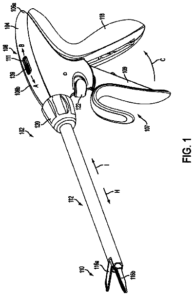
FIG. 1 is a perspective view of an endoscopic electrosurgical forceps according to an embodiment of the present disclosure;
FIG. 2 is a schematic, perspective view of jaw members coupled to a knife blade assembly configured for use with the endoscopic forceps depicted in FIG. 1 ;
FIG. 3 is a schematic, perspective view of a top jaw member depicted in FIG. 2 ;
FIGS. 4A and 4B are schematic, perspective views of a bottom jaw member depicted in FIG. 2 shown from respective top and bottom elevational perspectives;
FIG. 5 is a perspective view of the knife blade assembly depicted in FIG. 2 ;
FIG. 6 is a side, schematic, perspective view of the jaw members depicted in an open configuration and the knife blade assembly in a retracted configuration;
FIG. 7 is a side, schematic, perspective view of the jaw members depicted in a closed configuration and the knife blade assembly in a retracted configuration;
FIG. 8 is a side, schematic, perspective view of the jaw members depicted in a closed configuration and the knife blade assembly in an extended configuration;
FIG. 9 is side view of a knife blade assembly configured for use with the endoscopic forceps depicted in FIG. 1 according to another embodiment; and
FIG. 10 is a perspective view of an open electrosurgical forceps configured for use with a knife blade assembly according to an embodiment of the present disclosure.
Detailed embodiments of the present disclosure are disclosed herein; however, the disclosed embodiments are merely examples of the disclosure, which may be embodied in various forms. Therefore, specific structural and functional details disclosed herein are not to be interpreted as limiting, but merely as a basis for the claims and as a representative basis for teaching one skilled in the art to variously employ the present disclosure in virtually any appropriately detailed structure.
The forceps of the instant disclosure includes a unique knife lock-out mechanism that is configured to prevent inadvertent advancement of a knife blade assembly of the forceps. Specifically, a proximal end of one of a pair of jaw members of the forceps is configured to contact a knife stop on the knife blade assembly when the jaw members are in an open configuration. This proximal end may further be configured to guide the blade assembly into alignment with knife channels provided on the jaw members. Moreover, the proximal ends of the jaw members are configured to limit how far the jaw members may pivot away from and toward one another.
Turning now to FIG. 1 , an electrosurgical endoscopic forceps 2 (forceps 2 ) configured for use with a knife blade stop 40 ( FIGS. 5-8 ) is illustrated. Forceps 2 includes a housing 4 , a handle assembly 6 , a rotating assembly 8 , a trigger assembly 10 and an end effector assembly 12 . Forceps 2 includes a shaft 14 that extends from housing 4 and has a longitudinal axis “A-A” defined therethrough. A distal end 16 of shaft 14 is configured to mechanically engage end effector assembly 12 and a proximal end 18 is configured to mechanically engage housing 4 . Forceps 2 also includes an electrosurgical cable 20 that connects forceps 2 to a generator (not shown) or other suitable power source. Forceps 2 may alternatively be configured as a battery-powered instrument. Cable 20 includes a wire (or wires) (not explicitly shown) extending therethrough that has sufficient length to extend through shaft 14 in order to provide one or more suitable types of energy to one or both of a pair of jaw members 22 and 24 of end effector assembly 12 . The generator may be configured to provide electrosurgical energy (e.g., RF, microwave, optical, etc.), thermal energy, ultrasonic energy, and the like to jaw members 22 and 24 . In the illustrated embodiment, the generator is configured to provide RF energy to jaw members 22 and 24 .
Rotating assembly 8 is rotatable in either direction about longitudinal axis “A-A” to rotate end effector 12 about longitudinal axis “A-A” ( FIG. 1 ). Housing 4 houses the internal working components of forceps 2 , such as a drive assembly (not explicitly shown), working components of handle assembly 6 , electrical raceways associated with cable 20 , and other working components therein.
Handle assembly 6 includes a fixed handle 26 and a moveable handle 28 . Fixed handle 26 is integrally associated with housing 4 and movable handle 28 is moveable relative to fixed handle 26 . Moveable handle 28 connects to the drive assembly such that, together, movable handle 28 and the drive assembly mechanically cooperate to impart movement of jaw members 22 and 24 between a spaced-apart position and an approximated position to grasp tissue disposed between treatment surfaces 30 and 32 of jaw members 22 , 24 , respectively. As shown in FIG. 1 , moveable handle 28 is initially spaced-apart from fixed handle 26 and, correspondingly, jaw members 22 , 24 are in the spaced-apart position ( FIGS. 1 and 6 ). Moveable handle 28 is depressible from this initial position ( FIG. 1 ) to a depressed position (not explicitly shown) corresponding to the approximated position of jaw members 22 , 24 .
Other methods for opening and closing the jaw members 22 , 24 may be utilized. For example, any number of linkage devices, gears, vacuum tubes, actuators and the like may be utilized alone or in combination with the movable handle 24 and/or drive assembly to impart movement of the jaw members 22 , 24 from the spaced-apart position to the approximated position.
Continuing with reference to FIGS. 1-2 , end effector assembly 12 is designed as a bilateral assembly, i.e., where both jaw member 22 and jaw member 24 are moveable about pivot pin 34 relative to one another and to shaft 14 . End effector assembly 12 , however, may alternatively be configured as a unilateral assembly, i.e., where jaw member 24 is fixed relative to shaft 14 and jaw member 22 is moveable about pivot 34 relative to shaft 14 and fixed jaw member 24 .
Referring to FIG. 3 , jaw member 22 includes a proximal end 25 a and a distal end 25 b of suitable configuration that is configured to support treatment surface 30 thereon. Proximal end 25 a includes a bifurcated configuration defined by left and right sidewalls 29 a , 29 b having a suitable configuration to receive a proximal end 27 a of jaw member 24 (see FIG. 2 for example). Cam slots 35 a , 35 b are provided on sidewalls 29 a , 29 h and are configured to receive a cam pin 45 ( FIGS. 1-2 ) that is operably coupled to the drive assembly and is configured to impart movement of jaw members 22 , 24 when movable handle 28 is moved proximally. Moreover, apertures 48 a are defined through sidewalls 29 a , 29 h and are configured to receive pivot pin 34 therein to allow jaw members 22 , 24 to pivot thereabout when jaw members 22 , 24 are moved from the open configuration to the clamping configuration (and vice versa).
Continuing with reference to FIG. 3 , one or more mechanical interfaces are provided on proximal end 25 a and are configured to contact one or more corresponding mechanical interfaces provided on proximal end 27 a of jaw member 24 when jaw members 22 , 24 are in the clamping configuration. In the illustrated embodiment, for example, the mechanical interface provided on proximal end 25 a is in the form of a pair of protrusions 31 a , 31 b that extend inwardly from a bottom surface of respective sidewalls 29 a , 29 b . Protrusions 31 a , 31 b are configured to selectively engage a pair of corresponding notches 33 a , 33 b ( FIGS. 4A-4B ) provided on jaw member 24 to ensure a specific gap distance is maintained between jaw members 22 , 24 when jaw members 22 , 24 are in the clamping configuration (see FIGS. 2 and 7 for example).
A leading edge 44 ( FIGS. 2-3 ) is provided on proximal end 25 a and is configured to selectively contact a pair of corresponding leading edges 47 a , 47 b on proximal end 27 a ( FIGS. 4A-4B ) when jaw members 22 , 24 are moved to the open configuration. Contact between leading edge 44 and leading edges 47 a , 47 b prevents a user from opening jaw members 22 , 24 too far apart from one another (see FIG. 6 for example).
Referring to FIGS. 4A-4B , jaw member 24 includes proximal end 27 a and a distal end 27 b of suitable configuration that is configured to support treatment surface 32 thereon. Proximal end 27 a includes a bifurcated configuration defined by left and right sidewalls 41 a , 41 b . Sidewalls 41 a , 41 b define a cavity 43 of suitable configuration that is configured to receive a knife blade assembly 50 ( FIG. 2 ) therethrough. Cam slots 46 a , 46 b are provided on sidewalls 41 a , 41 b and are configured to receive cam pin 45 that functions to impart movement of jaw member 24 in a manner as described above. Apertures 48 b are defined through sidewalls 41 a , 41 b and are configured to receive pivot pin 34 therein. As noted above, leading edges 47 a , 47 b are configured to contact leading edge 44 and notches 33 a , 33 b are configured to contact protrusions 31 a , 31 b . A trailing edge 49 ( FIG. 4B ) is provided on jaw member 24 and is configured to selectively engage a knife blade assembly 50 to prevent distal translation of knife blade 52 , as will be described below. In embodiments, a pair of trailing edges 23 of the distal end 27 b may be configured to contact a proximal face 21 of the proximal end 25 a of the jaw member 22 to prevent a user from opening jaw members 22 , 24 too far apart from one another (see FIG. 6 for example).
In an assembled configuration proximal ends 25 a , 27 a of jaw members 22 , 24 , respectively, are nested with each other such that proximal end 27 a of jaw member 24 is movably seated within proximal end 25 a of jaw member 22 so as to allow jaw members 22 , 24 to move between the open and clamping configurations (as best seen in FIG. 2 ). Moreover, knife blade channels 53 (one knife channel shown in FIG. 1 ) are provided on jaw members 22 , 24 and are aligned with the knife blade assembly 50 to accommodate reciprocation of a knife blade 52 through jaw members 22 , 24 when a trigger 11 of the trigger assembly 10 is moved proximally ( FIGS. 1 and 2 ) and jaw members 22 , 24 are in the clamping configuration.
Referring now to FIG. 5 , knife blade assembly 50 is disposed within shaft 14 and is translatable therethrough from an initial, retracted configuration to an extended configuration into knife blade channels 53 on the jaw members 22 , 24 . Knife blade assembly 50 includes a generally elongated configuration having a split or bifurcated medial portion 55 defining opening 57 therebetween that is configured to receive pivot pin 34 and cam pin 45 therethrough ( FIG. 2 ).
A knife blade stop 40 ( FIG. 5 ) is provided on knife blade assembly 50 and is positioned proximally with respect to knife blade 52 to selectively contact a portion of jaw member 24 . Specifically, knife blade stop 40 is provided at a bottom portion of knife blade assembly 50 and includes a generally rectangular configuration having a leading edge 42 that is configured to contact trailing edge 49 of proximal end 27 a of jaw member 24 .
In embodiments (see FIG. 9 for example), a knife blade assembly 150 may include a knife blade stop 140 that includes a leading edge 142 . Unlike the knife blade stop 40 of the knife blade assembly 50 , the knife blade stop 140 extends substantially along a length of a bottom portion of the knife blade assembly 150 which provides a knife blade assembly 150 that is taller than known knife blade assemblies that are configured for use with conventional forceps.
In embodiments, it may prove useful to provide knife blade assemblies 50 , 150 including respective knife blade stops 40 , 140 that are thicker than conventional knife blade assemblies. As can be appreciated, the knife blade assemblies 50 , 150 may include a thickness that serves to strengthen the knife blades 52 , 152 which may reduce breakage thereof when the knife blade assemblies 50 , 150 are moved to advance the knife blades 52 , 152 distally through the jaw members 22 , 24 to sever tissue.
The thickness of the knife blade assemblies 50 , 150 and/or the knife stops 40 , 140 may be adjusted to achieve various effects and/or end results. For example, thicker knife blade assemblies 50 , 150 including the knife blade stops 40 , 140 may be utilized to facilitate guiding the knife blades 52 , 152 into alignment with the knife channels 53 on the jaw members 22 , 24 without the need for any additional part(s). That is, the thicker knife blade assemblies 50 , 150 including the knife blade stops 40 , 140 may be effectively “pinched” between the left and right sidewalls 41 a , 41 b of the proximal end 27 a of jaw member 24 as the knife blades 52 , 152 are advanced through the knife channel 53 on the jaw members 22 , 24 .
In use, jaw members 22 , 24 , initially, may be in the open configuration ( FIG. 6 ) so that a user may position tissue between jaw members 22 , 24 . In the open configuration, leading edge 42 of blade stop 40 contacts trailing edge 49 of jaw member 24 , which prevents distal translation of knife blade assembly 50 including knife blade 52 through jaw members 22 , 24 ( FIG. 6 ). Moreover, jaw members 22 , 24 are prevented from excessively pivoting (or opening) away from one another when large tissue is positioned therebetween. Specifically, contact between edges 47 a , 47 b and edge 44 prevents jaw members 22 , 24 from excessively pivoting away from one another.
Thereafter, movable handle 28 may be moved proximally to move jaw members 22 , 24 to a clamping configuration ( FIG. 7 ). In the clamping configuration, a predetermined gap distance (e.g., 0.001 inches to about 0.006 inches) is maintained between jaw members 22 , 24 as a result of notches 33 a , 33 b contacting protrusions 31 a , 31 b ; this also offloads some of the closure forces against cam pin 45 . In the clamping configuration, trailing edge 49 is rotated out of a path of translation of knife blade 52 and out of contact with leading edge 42 so as to allow advancement of the knife blade assembly 50 including knife blade 52 . Subsequently, trigger 11 of trigger assembly 10 may be actuated to move the knife blade assembly 50 including the knife blade 40 distally to advance the knife blade 52 through the knife channel 53 on the jaw members 22 , 24 to sever tissue ( FIG. 8 ). The left and right sidewalls 41 a , 41 b of the proximal end 27 a of jaw member 24 help guide the knife blade 52 into alignment with the knife channels 53 on the jaw members 22 , 24 .
The unique configuration of the blade stop 40 overcomes the aforementioned drawbacks that are typically associated with conventional forceps that utilize one or more components associated therewith to limit proximal and/or distal movement of the knife blade assembly. In particular, the likelihood of the knife blade assembly 50 including the knife blade 52 inadvertently moving between the jaw members 22 , 24 , such as, for example, when large tissue is positioned therebetween, is greatly reduced, if not completely eliminated. In other words, this greatly reduces, if not completely eliminates “blade trap” from occurring.
Moreover, providing jaw member 24 with notches 33 a , 33 b that are configured to contact corresponding protrusions 31 a , 31 b on jaw member 22 ensures that a specific gap distance is maintained between the jaw members 22 , 24 when the jaw members 22 , 24 are in the clamping configuration. As can be appreciated, this may prove advantageous during surgical procedures that require a specific gap distance between the jaw members when the jaw members are electrosurgically treating tissue, e.g., sealing tissue. Further, the overall manufacturing costs of the forceps 10 is kept relatively low as a result of being able to utilize the proximal end 27 a of jaw member 24 to help guide the knife blade 52 into alignment with the knife channels 53 .
From the foregoing and with reference to the various figure drawings, those skilled in the art will appreciate that certain modifications can also be made to the present disclosure without departing from the scope of the same. For example, in certain instances one or more resilient members, such as, for example, a spring or the like may be operably coupled to blade stop 40 to facilitate returning the knife blade assembly back to the retracted position.
While blade stop 40 has been described in terms of use with an endoscopic forceps, it is within the purview of the present disclosure that blade stop 40 may be configured for use with an open forceps 100 , see FIG. 10 for example. In this instance, blade stop 40 may be configured to accommodate the specific design of the open forceps.
While several embodiments of the disclosure have been shown in the drawings, it is not intended that the disclosure be limited thereto, as it is intended that the disclosure be as broad in scope as the art will allow and that the specification be read likewise. Therefore, the above description should not be construed as limiting, but merely as exemplifications of particular embodiments. Those skilled in the art will envision other modifications within the scope and spirit of the claims appended hereto.
About 4,625 words. The USPTO PDF has it with every drawing.
Fees are due 3.5, 7.5 and 11.5 years after grant. This patent expired on January 30, 2026, so the fee marked "not paid" was the one that went unpaid.
ELECTROSURGICAL INSTRUMENT WITH A KNIFE BLADE STOP
Filed Jan 2014 · published Sep 2014Electrosurgical instrument with a knife blade stop
Filed Jan 2014 · granted Jan 2018Earlier publications, parents and continuations. None of them can still be enforced, or this patent would not be listed.
Prior art cited by the examiner or applicant. Useful when you check your own idea for novelty.
Everything on this page comes from the documents linked above.