Lapsed, fee not paid10 drawings
Vehicles & Drones · US 9,840,247 B2
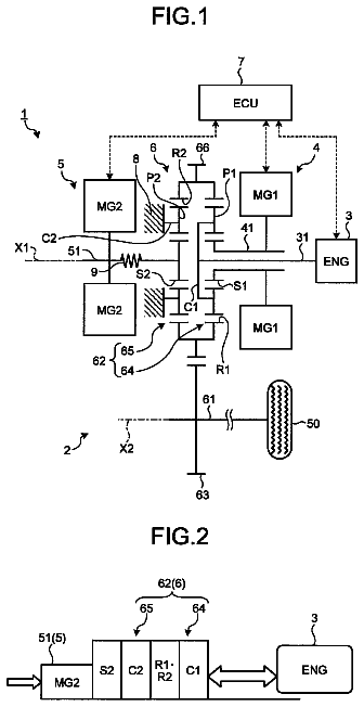
Hybrid vehicle
A hybrid vehicle includes an internal combustion engine, an electric power storage device, an electric motor, and an electronic control unit.
US 9,840,254 B2 · Assignee: SONY CORPORATION · Inventors: Gupta; Manish et al.
Sheet 1 of 10 from the published document. All sheets in the USPTO PDF
Various aspects of a system and method for an autonomous vehicle, based on detection and/or application of horn, are disclosed herein. The system comprises one or more circuits in an electronic control unit (ECU) used in a first vehicle. The one or more circuits in the ECU are configured to detect a horn sound emanated from a second vehicle. First sensor data associated with the first vehicle is captured based on the detected horn sound. The captured first sensor data indicates a first traffic scenario in a vicinity of the first vehicle. Second sensor data associated with the first vehicle is captured for an elapsed time interval prior to the detection of the horn sound. One or more control systems in the first vehicle are recalibrated to perform one or more functions associated with the first vehicle. The recalibration is based on the captured first sensor data and the extracted second sensor data.
Autonomous vehicle technology and/or Advanced Driving Assisting System (ADAS) are currently at a nascent stage. Various experiments are conducted related to the development of autonomous vehicle technology and/or the ADAS for use in vehicles, such as cars. Currently, vehicles with the ADAS are launched and several autonomous vehicles or working prototypes are undergoing the testing stage. In a scenario, a driver may observe an error in the operation of the autonomous vehicle or a vehicle with the ADAS including an autonomous braking system, a function of lane departure warning, and/or an autonomous cruise control system, etc. However, it may not always be possible for the driver to understand the problem accurately and utilize the related data. In another scenario, another vehicle user may honk at the autonomous vehicle or the vehicle with the ADAS for the improper driving. It may be des
1 of 10 drawing sheets so far from the published document, cropped to the drawing. Every sheet is in the USPTO PDF.
What the patent claimed, word for word. All of it is now free to use.
None.
Various embodiments of the disclosure relate to a system and method for an autonomous vehicle. More specifically, various embodiments of the disclosure relate to a system and method for an autonomous vehicle based on detection and/or application of a horn.
Autonomous vehicle technology and/or Advanced Driving Assisting System (ADAS) are currently at a nascent stage. Various experiments are conducted related to the development of autonomous vehicle technology and/or the ADAS for use in vehicles, such as cars. Currently, vehicles with the ADAS are launched and several autonomous vehicles or working prototypes are undergoing the testing stage.
In a scenario, a driver may observe an error in the operation of the autonomous vehicle or a vehicle with the ADAS including an autonomous braking system, a function of lane departure warning, and/or an autonomous cruise control system, etc. However, it may not always be possible for the driver to understand the problem accurately and utilize the related data. In another scenario, another vehicle user may honk at the autonomous vehicle or the vehicle with the ADAS for the improper driving. It may be desirable that machine learning is appropriately performed by the system of the autonomous vehicle or vehicle with the ADAS to rectify the improper driving for subsequent driving scenarios. In yet another scenario, it may be difficult for other road users to understand if they are the cause of some obstruction to the autonomous vehicle or vehicle with the ADAS on the road. Thus, an advanced, yet simplified technology may be required to improve the function and adaptability of the autonomous vehicle or vehicle with the ADAS.
Further limitations and disadvantages of conventional and traditional approaches will become apparent to one of skill in the art, through comparison of described systems with some aspects of the present disclosure, as set forth in the remainder of the present application and with reference to the drawings.
A system and a method for an autonomous vehicle, based on detection and/or application of a horn, substantially as shown in, and/or described in connection with, at least one of the figures, as set forth more completely in the claims.
These and other features and advantages of the present disclosure may be appreciated from a review of the following detailed description of the present disclosure, along with the accompanying figures in which like reference numerals refer to like parts throughout.
FIG. 1 is a block diagram that illustrates a network environment for an autonomous vehicle, in accordance with an embodiment of the disclosure.
FIG. 2 is a block diagram that illustrates various exemplary components or systems of an autonomous vehicle, in accordance with an embodiment of the disclosure.
FIGS. 3A and 3B illustrate a first exemplary scenario for implementation of the disclosed system and method for an autonomous vehicle, based on horn detection, in accordance with an embodiment of the disclosure.
FIGS. 4A and 4B illustrate a second exemplary scenario for implementation of the disclosed system and method for an autonomous vehicle, based on horn detection, in accordance with an embodiment of the disclosure.
FIGS. 5A and 5B illustrate a third exemplary scenario for implementation of the disclosed system and method for an autonomous vehicle, based on application of a horn, in accordance with an embodiment of the disclosure.
FIGS. 6A and 6B collectively depict a flow chart that illustrates an exemplary method for an autonomous vehicle, based on detection and/or application of a horn, in accordance with an embodiment of the disclosure.
The following described implementations may be found in the disclosed system and method for an autonomous vehicle, based on detection and/or application of a horn. Exemplary aspects of the disclosure may comprise a method that may detect a horn sound emanated from a second vehicle. First sensor data associated with the first vehicle may be captured based on the detected horn sound. The captured first sensor data may indicate a first traffic scenario in a vicinity of the first vehicle. Second sensor data associated with the first vehicle may be extracted for an elapsed time interval prior to the detection of the horn sound. One or more control systems in the first vehicle may be recalibrated to perform one or more functions associated with the first vehicle. The recalibration may be based on the captured first sensor data and the extracted second sensor data.
In accordance with an embodiment, the first vehicle and the second vehicle may operate in an autonomous mode, a semi-autonomous mode, or a manual mode. A position and/or a direction of the second vehicle may be determined with respect to the first vehicle, based on the captured first sensor data.
In accordance with an embodiment, the one or more functions may correspond to a change of lane, a change of speed, provision of lane change indication, and/or maintenance of a safe distance from one or more other vehicles. The one or more functions may further correspond to an application of a horn, an application of brakes, change in driving path of the first vehicle, generation of a safety alert, and/or performance of the one or more functions to avoid a violation of a traffic regulation.
In accordance with an embodiment, the first sensor data may correspond to a video stream of the first traffic scenario, vehicle data received from one or more connected vehicles in the vicinity of the first vehicle, and/or sensor data received from a radio wave-based object detection device or a laser-based object detection device. The second sensor data may correspond to a steering angle, a yaw rate, a speed value, lane information, a vehicle position accuracy data, a brake system status, a status of a vehicle stability system, and/or a rate-of-change of speed of the first vehicle.
In accordance with an embodiment, the captured first sensor data and the extracted second sensor data may be tagged with metadata that corresponds to the detection of the horn sound. The tagged first sensor data and the second sensor data may be utilized for the recalibration of the one or more control systems of the first vehicle. In accordance with an embodiment, the first traffic scenario may be identified for an automatic application of a horn by the first vehicle when the first vehicle is operated in an autonomous mode.
In accordance with another aspect of the disclosure, another method may comprise detection of an application of a horn at the first vehicle. The first sensor data associated with the first vehicle may be captured based on the detected application of the horn. The captured first sensor data may indicate a first traffic scenario in a vicinity of the first vehicle. Second sensor data associated with the first vehicle may be extracted for an elapsed time interval prior to the application of the horn at the first vehicle. One or more control systems in the first vehicle may be recalibrated to perform one or more functions associated with the first vehicle based on the captured first sensor data and the extracted second sensor data.
In accordance with an embodiment, the captured first sensor data and the extracted second sensor data may be tagged with metadata that corresponds to the application of the horn at the first vehicle. The recalibration of the one or more control systems in the first vehicle may be further based on the tagged first sensor data and extracted second sensor data when the application of the horn at the first vehicle is detected.
FIG. 1 is a block diagram that illustrates a network environment for an autonomous vehicle, in accordance with an embodiment of the disclosure. With reference to FIG. 1 , there is shown a network environment 100 . The network environment 100 may include a plurality of vehicles 102 , such as a first vehicle 102 a and a second vehicle 102 b . The network environment 100 may further include a cloud server 104 , a wireless communication network 106 , and one or more users. There is further shown an electronic control unit (ECU) 108 , image-capturing units 110 a to 110 d , and sound sensors 112 a to 112 g in the first vehicle 102 a . The one or more users may include a driver 114 associated with the first vehicle 102 a , and another driver 116 associated with the second vehicle 102 b . The plurality of vehicles 102 , which include the first vehicle 102 a and the second vehicle 102 b , may traverse along a road portion 118 . There is further shown a road side unit (RSU) 120 .
The ECU 108 may be communicatively coupled to the image-capturing units 110 a to 110 d and the sound sensors 112 a to 112 g , directly or indirectly via an in-vehicle network. In accordance with an embodiment, the ECU 108 may be communicatively coupled to the cloud server 104 , by communicating with the RSU 120 via the wireless communication network 106 . The RSU 120 may communicate with the cloud server 104 via the Internet or a suitable communication protocol known in the art.
The plurality of vehicles 102 may include the first vehicle 102 a , the second vehicle 102 b , and other vehicles that may traverse along the road portion 118 . In accordance with an embodiment, the plurality of vehicles 102 may be communicatively coupled to the wireless communication network 106 . The plurality of vehicles 102 may be configured to communicate vehicle data to the first vehicle 102 a . In accordance with an embodiment, the wireless communication network 106 may be used for a vehicle to vehicle (V2V) communication among the plurality of vehicles 102 . The wireless communication network 106 may also be used for a vehicle to infrastructure (V2I) communication between one of the plurality of vehicles 102 and the RSU 120 .
The first vehicle 102 a may refer to an autonomous vehicle that may operate in an autonomous mode, a semi-autonomous mode, or a manual mode. The first vehicle 102 a may comprise the ECU 108 , which may be configured to communicate with the cloud server 104 , and/or one or more other vehicles of the plurality of vehicles 102 , via the wireless communication network 106 . The second vehicle 102 b may refer to a non-autonomous vehicle or a vehicle that may operate in an autonomous mode, a semi-autonomous mode, or a manual mode. Examples of the plurality of vehicles 102 (which include the first vehicle 102 a and the second vehicle 102 b ) may include, but are not limited to, a motor vehicle, a hybrid vehicle, and/or a vehicle that uses one or more distinct renewable or non-renewable power sources. A vehicle that uses renewable or non-renewable power sources may include a fossil fuel-based vehicle, an electric propulsion-based vehicle, a hydrogen fuel-based vehicle, a solar-powered vehicle, and/or a vehicle powered by other forms of alternative energy sources. For example, the National Highway Traffic Safety Administration (NHTSA) in the United States proposes a classification for driving system as follows. The system and method of the present disclosure may be applied for vehicles with an autonomous function such as autonomous braking, autonomous cruise control, autonomous driving, etc. In the following examples, the system and method of the present disclosure may also be applied for vehicles from Level 1 to Level 4. According to the NHTSA, in “Level 0” category of vehicles, the driver completely controls the vehicle at all times. In “Level 1” category, individual vehicle controls may be automated, such as electronic stability control or automatic braking. In “Level 2” category, at least two controls may be automated together simultaneously, such as an adaptive cruise control together with a lane keeping control. In “Level 3” category, the level of autonomous control increases, where a vehicle may perform safety-critical functions in certain conditions. The vehicle may sense when conditions require the driver to retake control and provides a “sufficiently comfortable transition time” for the driver to do so. In “Level 4” category, the vehicle may perform all safety-critical functions where the driver is not expected to control the vehicle at any time. As this category of vehicle may control all functions from start to stop, including all parking functions, it may be a driverless vehicle.
The cloud server 104 may comprise suitable logic, circuitry, interfaces, and/or code that may be configured to establish a communication channel with one or more vehicles, such as the first vehicle 102 a . The cloud server 104 may be configured to store information received from one or more autonomous vehicles, such as the first vehicle 102 a . The cloud server 104 may be a web server, a database server, a file server, an application server, a cloud-based server, or a combination thereof. The cloud server 104 may be implemented by use of several technologies that are well known to those skilled in the art.
The wireless communication network 106 may include a medium through which the first vehicle 102 a may communicate with the cloud server 104 , and/or one or more other vehicles, such as the second vehicle 102 b . Examples of the wireless communication network 106 may include, but are not limited to, a dedicated short-range communication (DSRC) network, a mobile ad-hoc network (MANET), a vehicular ad-hoc network (VANET), Intelligent vehicular ad-hoc network (InVANET), Internet based mobile ad-hoc networks (IMANET), a wireless sensor network (WSN), a wireless mesh network (WMN), the Internet, a cellular network, such as a long-term evolution (LTE) network, a cloud network, a Wireless Fidelity (Wi-Fi) network, and/or a Wireless Local Area Network (WLAN). Various devices in the network environment 100 may be operable to connect to the wireless communication network 106 , in accordance with various wireless communication protocols. Examples of such wireless communication protocols may include, but are not limited to, IEEE 802.11, 802.11p, 802.15, 802.16, 1609, Worldwide Interoperability for Microwave Access (Wi-MAX), Wireless Access in Vehicular Environments (WAVE), cellular communication protocols, Transmission Control Protocol and Internet Protocol (TCP/IP), User Datagram Protocol (UDP), Hypertext Transfer Protocol (HTTP), Long-term Evolution (LTE), File Transfer Protocol (FTP), ZigBee, EDGE, infrared (IR), and/or Bluetooth (BT) communication protocols.
The ECU 108 may comprise suitable logic, circuitry, interfaces, and/or code that may be configured to detect that a horn sound is emanated from one or more of the plurality of vehicles 102 , such as the second vehicle 102 b . The ECU 108 may be a test ECU that may help improve the drive accuracy of the first vehicle 102 a on a road, such as the road portion 118 , when the first vehicle 102 a is in an autonomous mode. The ECU 108 may be configured to access sensor data of the first vehicle 102 a , or to communicate one or more control commands to other ECUs, components, or systems of the first vehicle 102 a . The sensor data may be accessed by the ECU 108 , via an in-vehicle network, such as a controller area network (CAN) bus. In accordance with an embodiment, the ECU 108 may be configured to receive vehicle data from one or more connected vehicles from the plurality of vehicles 102 in a vehicle-to-vehicle (V2V) communication, via a wireless communication system. In accordance with an embodiment, the ECU 108 may be configured to receive vehicle data of one or more connected vehicles from the cloud server 104 in an infrastructure-to-vehicle (12V) communication. In such a case, the one or more connected vehicles from the plurality of vehicles 102 may communicate corresponding vehicle data to the cloud server 104 beforehand, in a vehicle-to-infrastructure (V2I) communication. One or more horn signals may be communicated between two vehicles, such as the first vehicle 102 a and the second vehicle 102 b , of the plurality of vehicles 102 via the V2V communication instead of using horn sounds (honking). In this case, the plurality of vehicles 102 have a function of sending and receiving a horn signal via the V2V communication. The first vehicle 102 a may receive and detect a horn signal from other vehicles of the plurality of vehicles 102 as a warning information via the V2V communication.
The image-capturing units 110 a to 110 d may comprise suitable logic, circuitry, interfaces, and/or code that may be configured to capture one or more video streams of a road portion, such as the road portion 118 . The video streams may include a plurality of image frames within one or more fields-of-view (FOVs) of the image-capturing units 110 a to 110 d . The image-capturing units 110 a to 110 d may be configured to record time of capture of each frame of the plurality of image frames in the captured one or more video streams. Examples of the image-capturing units 110 a to 110 d may include, but are not limited to, an image sensor, a wide-angle camera, a closed-circuit television (CCTV) camera, a camcorder, an in-built camera of a smart-glass, and/or other such vehicle cameras. In accordance with an embodiment, the image-capturing unit 110 a may be installed at the rear side of a vehicle body of the first vehicle 102 a . The image-capturing units 110 b and 110 d may be installed at outside rear view mirrors (ORVM) of the first vehicle 102 a (as shown). The image-capturing unit 110 c may be installed at the front side of the vehicle body of the first vehicle 102 a . In accordance with an embodiment, instead of multiple image-capturing units, such as the image-capturing units 110 a to 110 d , one rotatable image-capturing unit may be provided that may be configured to capture a 360 degree view of the road portion 118 in the vicinity of the first vehicle 102 a.
The sound sensors 112 a to 112 g may refer to sensors or transducers that convert sound energy into electrical signals. The sound sensors 112 a to 112 g may be configured to capture horn sound, measure sound pressure, and/or acoustic particle velocity of a sound field, such as a sound wave of horn sound. Horn sound generated by automobiles, such as a four wheeler, a three wheeler, or a two wheeler, may comprise a certain distinct pitch and loudness values. The sound sensors 112 a to 112 g may comprise audio filters that may be configured to capture sounds (such as horn sounds) in pre-defined range of pitch, loudness, and sound duration such as to filter out other noise on the road portion 118 . The sound sensors 112 a to 112 g may be communicatively coupled to the ECU 108 . The sound sensors 112 a to 112 g may be positioned at one or more locations of the first vehicle 102 a , as shown in FIG. 1 .
The RSU 120 may be configured to wirelessly communicate to the plurality of vehicles 102 on the road portion 118 . The RSU 120 may be further configured to communicate with the cloud server 104 via the Internet, or a suitable communication protocol known in the art. The RSU 120 may correspond to an infrastructure unit or a communication device installed at the road portion 118 . In accordance with an embodiment, multiple RSUs similar to the RSU 120 may be installed along the road portion 118 or other road portions.
In operation, the sound sensors 112 a to 112 g may be configured to capture a horn sound emanated from one of the plurality of vehicles 102 . The ECU 108 may be configured to detect the horn sound and/or a direction of the horn sound emanated from one of the plurality of vehicles 102 , such as the second vehicle 102 b , and captured by the sound sensors 112 a to 112 g . The ECU 108 may be configured to capture first sensor data associated with the first vehicle 102 a , based on the detected horn sound. The captured first sensor data indicates a first traffic scenario in a vicinity of the first vehicle 102 a.
In accordance with an embodiment, the captured first sensor data may correspond to a video stream of the first traffic scenario. The video stream may be captured by at least one of the image-capturing units 110 a to 110 d . The captured first sensor data may further correspond to vehicle data received from one or more connected vehicles in the vicinity of the first vehicle 102 a , and/or sensor data received from one or more sensors, such as a radio detection and ranging (RADAR) device, installed at the first vehicle 102 a.
In accordance with an embodiment, the ECU 108 may be configured to determine a position and/or a direction of the second vehicle 102 b , with respect to the first vehicle 102 a , based on the captured first sensor data. The ECU 108 may be further configured to extract second sensor data associated with the first vehicle 102 a . The second sensor data may be extracted for an elapsed time interval prior to the detection of the horn sound. The second sensor data may correspond to in-vehicle data, such as a steering angle, a yaw rate, a speed value, lane information, and/or a rate-of-change of speed, associated with the first vehicle 102 a.
In accordance with an embodiment, the ECU 108 may be configured to tag the captured first sensor data and the extracted second sensor data with metadata. The metadata may correspond to the detection of the horn sound. The ECU 108 may be configured to recalibrate one or more control systems in the first vehicle 102 a , to perform one or more functions associated with the first vehicle 102 a . The recalibration of the one or more control systems in the first vehicle 102 a may be based on the captured and tagged first sensor data and the extracted second sensor data.
In accordance with an embodiment, the one or more functions may correspond to a change of lane, a change of speed, provision of lane change indication, maintenance of a safe distance from one or more other vehicles, an application of a horn, and/or an application of brakes at first vehicle 102 a . The one or more functions may further correspond to a change in driving path of the first vehicle 102 a and generation of a safety alert via a display unit and/or the audio interface (described in detail in FIG. 2 ). In accordance with an embodiment, the one or more functions may be performed to avoid violation of a traffic regulation.
In accordance with an embodiment, the tagged first sensor data and the second sensor data may be communicated to the cloud server 104 . The cloud server 104 may be configured to store the tagged first sensor data and the second sensor data. The cloud server 104 may be further configured to analyze the tagged first sensor data and the second sensor data. The analysis may be performed to determine events around the time of detection of the horn sound and/or to determine a relationship between the second sensor data and the captured first sensor data.
In accordance with an embodiment, the cloud server 104 may store learned data, such as the tagged second sensor data, in an associative relationship with the first sensor data. The cloud server 104 may be configured to communicate the learned data to the ECU 108 of the first vehicle 102 a , so that when a similar traffic scenario, such as the first traffic scenario, is encountered in future by the first vehicle 102 a , the first vehicle 102 a may automatically perform the one or more functions, as described above.
Although for simplicity, FIG. 1 does not show a roadside unit (RSU), one skilled in the art may appreciate that the captured first sensor data and the second sensor data may also be communicated to the RSU for storage and analysis, via the wireless communication network 106 . The analysis result may be communicated to other vehicles, such as the first vehicle 102 a and/or the second vehicle 102 b , to improve the drive in autonomous mode. The operations performed at the ECU 108 of the first vehicle 102 a are further described in detail in FIGS. 2, 3A, 3B, 4A, and 4B .
FIG. 2 is a block diagram that illustrates various exemplary components or systems of an autonomous vehicle, in accordance with an embodiment of the disclosure. FIG. 2 is explained in conjunction with elements from FIG. 1 . With reference to FIG. 2 , there is shown the first vehicle 102 a . The first vehicle 102 a may comprise the ECU 108 that may include a microprocessor 202 and a memory 204 . The first vehicle 102 a may further comprise a wireless communication system 206 , an audio interface 208 , a display screen 210 , an outside rear view mirror (ORVM) 212 , a powertrain control system 214 , a steering system 216 , a braking system 218 , a sensing system 220 , a horn control system 222 , an object detection device 224 , an in-vehicle network 226 , and a vehicle body 228 . The sensing system 220 may include one or more image-capturing units, such as the image-capturing units 110 a to 110 d , the sound sensors 112 a to 112 g , and the object detection device 224 .
The various components or systems may be communicatively coupled to each other, via the in-vehicle network 226 , such as a vehicle area network (VAN), and/or an in-vehicle data bus. The microprocessor 202 may be communicatively coupled to the memory 204 , the audio interface 208 , the display screen 210 , the ORVM 212 , the wireless communication system 206 , the powertrain control system 214 , the sensing system 220 , and the horn control system 222 , via the in-vehicle network 226 . It should be understood that the first vehicle 102 a may also include other suitable components or systems, but for brevity, those components or systems which are used to describe and explain the function and operation of the present disclosure are illustrated herein.
The microprocessor 202 may comprise suitable logic, circuitry, interfaces, and/or code that may be configured to execute a set of instructions stored in the memory 204 . Examples of the microprocessor 202 may be an X86-based processor, a Reduced Instruction Set Computing (RISC) processor, an Application-Specific Integrated Circuit (ASIC) processor, a Complex Instruction Set Computing (CISC) processor, an Explicitly Parallel Instruction Computing (EPIC) processor, a Very Long Instruction Word (VLIW) processor, a microcontroller, a central processing unit (CPU), a graphics processing unit (GPU), a state machine, and/or other processors or circuits.
The memory 204 may comprise suitable logic, circuitry, and/or interfaces that may be configured to store a machine code and/or a set of instructions with at least one code section executable by the microprocessor 202 . The memory 204 may be further operable to store the tagged first sensor data and the second sensor data. Examples of implementation of the memory 204 may include, but are not limited to, Electrically Erasable Programmable Read-Only Memory (EEPROM), Random Access Memory (RAM), Read Only Memory (ROM), Hard Disk Drive (HDD), Flash memory, a Secure Digital (SD) card, Solid-State Drive (SSD), and/or CPU cache memory.
The wireless communication system 206 may comprise suitable logic, circuitry, interfaces, and/or code that may be configured to communicate with one or more external devices, such as the cloud server 104 , under the control of the microprocessor 202 . Such communication with the one or more external devices may occur by use of the wireless communication network 106 . The wireless communication system 206 may include various components, which are not limited to, an antenna, a telematics unit, a radio frequency (RF) transceiver, one or more amplifiers, one or more oscillators, a digital signal processor, a near field communication (NFC) circuitry, a coder-decoder (CODEC) chipset, and/or a subscriber identity module (SIM) card.
The wireless communication system 206 may communicate with networks, such as the wireless communication network 106 under the control of the microprocessor 202 , via a wireless communication protocol, such as a dedicated short-range communication (DSRC) protocol. The wireless communication system 206 may use any of a plurality of communication standards, protocols and technologies, such as the global system for mobile communications (GSM), enhanced data GSM environment (EDGE), wideband code division multiple access (W-CDMA), code division multiple access (CDMA), long term evolution (LTE), time division multiple access (TDMA), Bluetooth (BT), Wireless Fidelity (Wi-Fi) (such as IEEE 802.11a, IEEE 802.11b, IEEE 802.11g and/or IEEE 802.11n), voice over Internet Protocol (VoIP), Wi-MAX, a protocol for email, instant messaging, and/or Short Message Service (SMS).
The audio interface 208 may be connected to a speaker, a chime, a buzzer, or other device that may be operable to generate a sound. The audio interface 208 may also be connected to a microphone or other device to receive a voice input from an occupant of the first vehicle 102 a , such as the driver 114 . The display screen 210 may refer to a touch screen to receive an input from the driver 114 and to display various types of information to occupants of the first vehicle 102 a , such as the driver 114 . The first vehicle 102 a may include other input/output (I/O) devices that may be configured to communicate with the microprocessor 202 . The audio interface 208 may be a part of an infotainment unit or a head unit of the first vehicle 102 a . In accordance with an embodiment, in-vehicle communication of audio/video data for multimedia components may occur by use of Media Oriented Systems Transport (MOST) multimedia network protocol of the in-vehicle network 226 . Examples of the display screen 210 may include, but are not limited to, a display of the head unit, a tablet computer, a computing device with an electronic display, a heads-up display (HUD), a heads-up display with an augmented reality system (AR-HUD), a driver information console (DIC), a projection-based display, a see-through display, a smart-glass display, and/or an electro-chromic display. In accordance with an embodiment, the image-capturing units 110 b and 110 d may be installed at the ORVM 212 of the first vehicle 102 a (as shown in FIG. 1 ).
The powertrain control system 214 may refer to an onboard computer of the first vehicle 102 a that controls operations of an engine and a transmission system of the first vehicle 102 a . The powertrain control system 214 may control the engine's ignition, fuel injection, emission systems, and/or operations of the transmission system (such as automatic transmission system) and the braking system 218 . The transmission system may refer to a manual transmission, a synchronized transmission, a fully automatic transmission, a semi-automatic transmission, a Continuously Variable Transmission (CVT), a sequential transmission, dual-clutch transmission (DCT), or other transmission known in the art.
The steering system 216 may be associated with the powertrain control system 214 . The steering system 216 may include a steering wheel and/or an electric motor (provided for a power-assisted steering) that may be used by the driver 114 to control movement of the first vehicle 102 a in manual mode or a semi-autonomous mode. In accordance with an embodiment, the movement or steering of the first vehicle 102 a may be automatically controlled when the first vehicle 102 a is in autonomous mode. Examples of the steering system 216 may include, but are not limited to, an autonomous steering control, a power-assisted steering system, a vacuum/hydraulic-based steering system, an electro-hydraulic power-assisted system (EHPAS), or a “steer-by-wire” system, known in the art.
The braking system 218 may be used to stop or slow down the first vehicle 102 a by application of frictional forces. The braking system 218 may be configured to receive a command from the powertrain control system 214 under the control of the microprocessor 202 , when the first vehicle 102 a is in an autonomous mode or a semi-autonomous mode.
The sensing system 220 may comprise the image-capturing units 110 a to 110 d , the sound sensors 112 a to 112 g , the object detection device 224 , and/or one or more other vehicle sensors provided in the first vehicle 102 a . The sensing system 220 may be operatively connected to the ECU 108 , via the in-vehicle network 226 , to provide input signals to the microprocessor 202 . One or more communication interfaces, such as a CAN interface, may be provided in the sensing system 220 to connect to the in-vehicle network 226 . The object detection device 224 may be the RADAR device and/or a laser-based object detection sensor, such as a light detection and ranging (LIDAR) device. Examples of the one or more vehicle sensors of the sensing system 220 may include, but are not limited to, a vehicle speed sensor, the odometric sensors, a yaw rate sensor, a speedometer, a global positioning system (GPS), a steering angle detection sensor, a vehicle travel direction detection sensor, a magnometer, an image sensor, a touch sensor, and/or an infrared sensor. The one or more vehicle sensors of the sensing system 220 may be configured to detect a direction of travel, geospatial position, steering angle, yaw rate, speed, and/or rate-of-change of speed of the first vehicle 102 a.
The horn control system 222 may be communicatively coupled to the ECU 108 via the in-vehicle network 226 . The horn control system 222 may be configured to automatically apply the horn based on a command received from the microprocessor 202 when the first vehicle 102 a is in the autonomous mode. The horn control system 222 may be connected to a horn switch (not shown) that may receive input from a user, such as the driver 114 , for application of the horn in the first vehicle 102 a in a manual mode or semi-autonomous mode. When the horn switch is pressed, a horn signal may be relayed to the horn via the in-vehicle network 226 . The horn may refer to an automobile horn used to produce a sound to alarm others (usually referred to as honking) while driving on a road, such as the road portion.
The in-vehicle network 226 may include a medium through which the various components or systems of the first vehicle 102 a , such as the ECU 108 , the horn control system 222 , the powertrain control system 214 , the sensing system 220 , and/or the wireless communication system 206 , may communicate with each other. The in-vehicle network 226 may facilitate access control and/or communication between the microprocessor 202 and other ECUs, such as the horn control system 222 or a body control module, of the first vehicle 102 a . Various devices in the first vehicle 102 a may be configured to connect to the in-vehicle network, in accordance with various wired and wireless communication protocols. One or more communication interfaces, such as the CAN interface, a Local Interconnect Network (LIN) interface, a Media Oriented Systems Transport (MOST) interface, may be used by the various components or systems of the first vehicle 102 a to connect to the in-vehicle network 226 . Examples of the wired and wireless communication protocols for the in-vehicle network may include, but are not limited to, a vehicle area network (VAN), a CAN bus, Domestic Digital Bus (D2B), Time-Triggered Protocol (TTP), FlexRay, IEEE 1394, Carrier Sense Multiple Access With Collision Detection (CSMA/CD) based data communication protocol, Inter-Integrated Circuit (I.sup.2C), Inter Equipment Bus (IEBus), Society of Automotive Engineers (SAE) J1708, SAE J1939, International Organization for Standardization (ISO) 11992, ISO 11783, Media Oriented Systems Transport (MOST), MOST25, MOST50, MOST150, Plastic optical fiber (POF), Power-line communication (PLC), Serial Peripheral Interface (SPI) bus, and/or Local Interconnect Network (LIN).
The vehicle body 228 may refer to an outer shell (such as outer panels and/or a frame assembly other than chassis) of the first vehicle 102 a , which cover the various components and systems as described above, and other mechanical and electrical workings or components of a vehicle, such as the first vehicle 102 a . A body type of the vehicle body 228 may be a unitized body (or a uni-body), a body-on-frame, a body with ancillary sub-frames, a dual frame body, and/or other body structures known in the art. A body style of the vehicle body 228 may be a sports utility vehicle (SUV), a van, a truck, a sedan, a coupe, a convertible, a hatchback, a sports car, and/or other body styles known in the art.
In operation, one or more of the plurality of vehicles 102 may apply a horn in one or more traffic scenarios at the road portion 118 . For example, when a driver, such as the driver 116 , of the second vehicle 102 b observes an improper driving or a mistake in the driving of an autonomous vehicle, such as the first vehicle 102 a , the driver 116 (of second vehicle 102 b ) may apply the horn to alarm the first vehicle 102 a . Consequently, a horn sound may emanate from a horn (not shown) of the second vehicle 102 b.
In accordance with an embodiment, the sound sensors 112 a to 112 g may be configured to capture the horn sound emanated from one of the plurality of vehicles 102 , such as the second vehicle 102 b . The microprocessor 202 may be configured to ascertain whether the captured horn sound is a horn sound emanated from the horn of the first vehicle 102 a or other vehicles, such as the second vehicle 102 b , of the plurality of vehicles 102 . In such a case, the microprocessor 202 of the first vehicle 102 a may check presence of a horn signal for self-application of the horn, in the in-vehicle network 226 , such as the CAN bus.
In instances when the horn signal is not found in the in-vehicle network 226 , the microprocessor 202 may be configured to detect that the horn sound captured by the sound sensors 112 a to 112 g is emanated by one of the plurality of vehicles 102 , such as the second vehicle 102 b , in the vicinity of the first vehicle 102 a . The microprocessor 202 may be configured to determine a direction of the horn sound by use of the sound sensors 112 a to 112 g . For example, a time difference of arrival (TDOA) method, a triangulation method, and/or measurement of the acoustic particle velocity of a sound field, such as the sound field of the emanated horn sound, may be employed for the determination of the direction of the horn sound.
In accordance with an embodiment, the microprocessor 202 may be configured to capture first sensor data associated with the first vehicle 102 a , based on the detected horn sound. The captured first sensor data indicates a first traffic scenario in a vicinity of the first vehicle 102 a . The first traffic scenario may correspond to occurrence of events on a road, such as the road portion 118 , for a certain time interval (such as “up to 20 seconds”), at the time of detection of the horn sound. The events may refer to a change in speed, a change of lane, a change in driving path, and/or a relative position of the plurality of vehicles 102 in the vicinity of the first vehicle 102 a . The events may also refer to a presence or sudden appearance of pedestrians, an animal, and/or other obstacles on the road portion 118 . The events may further refer to a sudden acceleration or deceleration by one or more vehicles in the vicinity of the first vehicle 102 a on the road portion 118 . The events may further refer to the sudden application of brakes and/or disobedience of traffic rules related to one or more of the plurality of the vehicles 102 . The events may lead to a certain traffic scenario, such as the first traffic scenario, on the road portion 118 , due to which one or more of the plurality of vehicles 102 may apply the horn.
The description continues in the full USPTO document.
About 6,755 words. The USPTO PDF has it with every drawing.
Fees are due 3.5, 7.5 and 11.5 years after grant. This patent expired on December 12, 2025, so the fee marked "not paid" was the one that went unpaid.
METHOD AND SYSTEM FOR ADAPTIVE DETECTION AND APPLICATION OF HORN FOR AN AUTONOMOUS VEHICLE
Filed Dec 2015 · published Jul 2017Method and system for adaptive detection and application of horn for an autonomous vehicle
Filed Dec 2015 · granted Dec 2017Earlier publications, parents and continuations. None of them can still be enforced, or this patent would not be listed.
Prior art cited by the examiner or applicant. Useful when you check your own idea for novelty.
Everything on this page comes from the documents linked above.