Cross-reference to related application
This is a national phase application based on the PCT International Patent Application No. PCT/JP2013/053145 filed Feb. 8, 2013, the entire contents of which are incorporated herein by reference.
Field
The present invention relates to a vehicle drive apparatus.
Background
As a vehicle drive apparatus to be mounted on a vehicle, for example, Patent Literature 1 discloses a vehicle drive apparatus that includes a plurality of planetary gear mechanisms and is applied to a hybrid vehicle, which includes both an internal combustion engine and an electric motor as power sources for running. CITATION LIST Patent Literature
Patent Literature 1: Japanese Laid-open Patent Publication No. 2012-81886 SUMMARY Technical Problem
Incidentally, the above-described vehicle drive apparatus described in Patent Literature 1 has room for further improvement in, for example, suppression of sound noise (or vibration).
The present invention has been made in view of the above-described circumstances, and it is an object of the present invention to provide a vehicle drive apparatus that allows suppressing the occurrence of sound noise. Solution to Problem
To achieve the above-described object, a vehicle drive apparatus according to the present invention includes: an engine; a rotary machine; an output member coupled to a drive wheel of a vehicle; a differential mechanism configured to couple the engine, the rotary machine, and the output member together to be differentially rotatable via a plurality of differentially rotatable rotational elements; and an elastic member configured to couple a rotation shaft of the rotary machine to the rotational element of the differential mechanism to be relatively rotatable.
The vehicle drive apparatus may include a control device configured to execute a torque control that controls the rotary machine to cause the rotary machine to output a pressing torque reducing a gap in an engaging portion between the plurality of rotational elements.
In the vehicle drive apparatus, the elastic member may be disposed within the rotation shaft of the rotary machine.
The vehicle drive apparatus may include a holding mechanism including: a rotation-shaft-side rotating member disposed within the rotation shaft of the rotary machine and configured to rotate integrally with the rotation shaft; and a rotational-element-side rotating member disposed within the rotation shaft of the rotary machine and configured to rotate integrally with the rotational element of the differential mechanism. The holding mechanism holds the elastic member between the rotation-shaft-side rotating member and the rotational-element-side rotating member. The rotation-shaft-side rotating member and the rotational-element-side rotating member are relatively rotatable within a range of a torsion angle that allows a required range corresponding to an output variation in the engine.
In the vehicle drive apparatus, the rotation-shaft-side rotating member may be formed in a pipe shape. The rotational-element-side rotating member may be formed in a plate shape and may be inserted into the rotation-shaft-side rotating member. The elastic member may be constituted by a wave-shaped leaf spring and may be interposed between an inner surface of the rotation-shaft-side rotating member and an outer surface of the rotational-element-side rotating member.
In the vehicle drive apparatus, the rotational-element-side rotating member may be formed in a rod shape and may include one end portion having a rotational-element-side engaging groove. The rotation-shaft-side rotating member may be formed on another end portion side of the rotational-element-side rotating member and may include a rotation-shaft-side engaging groove. The elastic member may be constituted by a coil spring and may be configured to allow insertion of the rotational-element-side rotating member on an inner side of the elastic member. The elastic member may include one end engaged with the rotational-element-side engaging groove and another end engaged with the rotation-shaft-side engaging groove.
The vehicle drive apparatus may include a hitting-sound detecting device configured to detect occurrence of hitting sound in the engaging portion between the plurality of rotational elements. The control device is configured to change the pressing torque based on a detection result by the hitting-sound detecting device.
The vehicle drive apparatus may include a temperature detecting device configured to detect a temperature of a cooling medium for cooling the engine. The control device is configured to change the pressing torque based on a detected temperature of the cooling medium by the temperature detecting device.
In the vehicle drive apparatus, the differential mechanism may include a first planetary gear mechanism and a second planetary gear mechanism. The rotary machine may couple to the engine via the first planetary gear mechanism and the second planetary gear mechanism and may receive a reactive force of a rotating power generated by the engine when the rotating power of the engine transmits to the drive wheel. Advantageous Effects of Invention
The vehicle drive apparatus according to the present invention provides an advantageous effect that allows suppressing the occurrence of sound noise.
Brief description of drawings
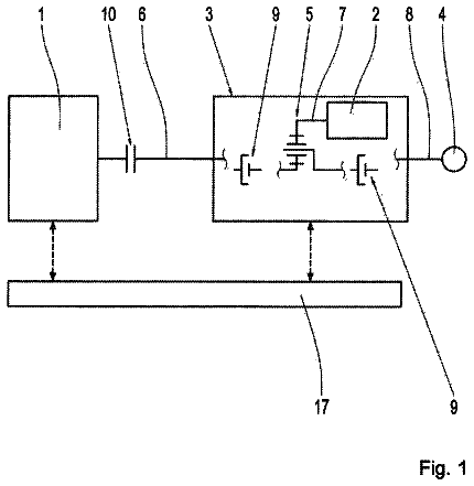
FIG. 1 is a schematic configuration diagram of a vehicle equipped with a vehicle drive apparatus according to a first embodiment.
FIG. 2 is a schematic diagram illustrating the rotational elements between an engine and a rotary machine as a linear model.
FIG. 3 is a schematic diagram illustrating the rotational elements between the engine and the rotary machine as a linear model.
FIG. 4 is a schematic diagram illustrating the rotational elements between the engine and the rotary machine as a linear model.
FIG. 5 is a schematic diagram illustrating the rotational elements between the engine and the rotary machine as a linear model.
FIG. 6 is a schematic diagram describing estimation of rattling-noise occurrence positions.
FIG. 7 is a schematic diagram illustrating the rotational elements between the engine and a second rotary machine according to the vehicle drive apparatus according to the first embodiment as a linear model.
FIG. 8 is a graph describing one example of the operation of the vehicle drive apparatus according to the first embodiment.
FIG. 9 is a timing chart chronologically illustrating the transition of the sum of an engine torque and a pressing-torque effective value in the vehicle drive apparatus according to the first embodiment.
FIG. 10 is a partial cross-sectional view, including a holding mechanism, of the vehicle drive apparatus according to the first embodiment.
FIG. 11 is a cross-sectional view (an A-A cross-sectional view of FIG. 10 ) of the holding mechanism of the vehicle drive apparatus according to the first embodiment.
FIG. 12 is a cross-sectional view (a cross-sectional view along a rotation axis line X 1 ) of a sleeve of the vehicle drive apparatus according to the first embodiment.
FIG. 13 is a C direction arrow view of FIG. 12 .
FIG. 14 is a partial side view of a coupling shaft of the vehicle drive apparatus according to the first embodiment.
FIG. 15 is a D direction arrow view of FIG. 14 .
FIG. 16 is a cross-sectional view (a B-B cross-sectional view of FIG. 10 ) of the coupling shaft of the vehicle drive apparatus according to the first embodiment.
FIG. 17 is a side view of an elastic member of the vehicle drive apparatus according to the first embodiment.
FIG. 18 is an E direction arrow view of FIG. 17 .
FIG. 19 is a graph representing one example of a torsional property in the vehicle drive apparatus according to the first embodiment.
FIG. 20 is a partial cross-sectional view including the holding mechanism of the vehicle drive apparatus according to a second embodiment.
FIG. 21 is a schematic configuration diagram of a vehicle equipped with a vehicle drive apparatus according to a third embodiment.
FIG. 22 is a schematic diagram describing an installation example of a hitting-sound detecting device of the vehicle drive apparatus according to the third embodiment.
FIG. 23 is a schematic diagram describing a configuration example of the hitting-sound detecting device of the vehicle drive apparatus according to the third embodiment.
FIG. 24 is a schematic configuration diagram of a vehicle equipped with a vehicle drive apparatus according to a fourth embodiment.
FIG. 25 is a flowchart describing one example of a control in the vehicle drive apparatus according to the fourth embodiment.
FIG. 26 is a graph representing one example of a pre-torque-control map in a vehicle drive apparatus according to a fourth embodiment.
Description of embodiments
The following describes embodiments according to the present invention with reference to the drawings. Note that the present invention is not limited to these embodiments. Also, the components of the embodiments described below encompass components that can be easily replaced by a person skilled in the art or components that are substantially identical. First Embodiment
FIG. 1 is a schematic configuration diagram of a vehicle equipped with a vehicle drive apparatus according to a first embodiment. FIGS. 2, 3, 4, and 5 are schematic diagrams illustrating the rotational elements between an engine and a rotary machine as a linear model. FIG. 6 is a schematic diagram describing estimation of rattling-noise occurrence positions. FIG. 7 is a schematic diagram illustrating the rotational elements between the engine and a second rotary machine in the vehicle drive apparatus according to the embodiment as a linear model. FIG. 8 is a graph describing one example of the operation of the vehicle drive apparatus according to the first embodiment. FIG. 9 is a timing chart chronologically illustrating the transition of the sum of an engine torque and a pressing-torque effective value in the vehicle drive apparatus according to the first embodiment. FIG. 10 is a partial cross-sectional view, including a holding mechanism, of the vehicle drive apparatus according to the first embodiment. FIG. 11 is a cross-sectional view (an A-A cross-sectional view of FIG. 10 ) of the holding mechanism of the vehicle drive apparatus according to the first embodiment. FIG. 12 is a cross-sectional view (a cross-sectional view along a rotation axis line X 1 ) of a sleeve of the vehicle drive apparatus according to the first embodiment. FIG. 13 is a C direction arrow view of FIG. 12 . FIG. 14 is a partial side view of a coupling shaft of the vehicle drive apparatus according to the first embodiment. FIG. 15 is a D direction arrow view of FIG. 14 . FIG. 16 is a cross-sectional view (a B-B cross-sectional view of FIG. 10 ) of the coupling shaft of the vehicle drive apparatus according to the first embodiment. FIG. 17 is a side view of an elastic member of the vehicle drive apparatus according to the first embodiment. FIG. 18 is an E direction arrow view of FIG. 17 . FIG. 19 is a graph representing one example of a torsional property in the vehicle drive apparatus according to the first embodiment.
A vehicle drive apparatus 1 according to this embodiment illustrated in FIG. 1 is mounted on a vehicle 2 . The vehicle drive apparatus 1 is a hybrid drive system in a hybrid type that is equipped with: an engine 3 ; and a first rotary machine 4 and a second rotary machine 5 as rotary machines, as power sources (power engines) for running to rotatably drive a drive wheel 50 of the vehicle 2 so as to drive forward. That is, the vehicle 2 is what is called a hybrid vehicle, and is a vehicle that includes the first rotary machine 4 and the second rotary machine 5 as the power sources in addition to the engine 3 . While the vehicle 2 operates the engine 3 in an efficient state as much as possible, the vehicle 2 causes the first rotary machine 4 and the second rotary machine 5 to: compensate excess and shortage of the driving force and the engine braking force; and further regenerate energy during deceleration. Accordingly, the vehicle 2 is a vehicle configured to reduce the exhaust gas from the engine 3 and simultaneously improve the fuel efficiency.
Specifically, the vehicle drive apparatus 1 includes the engine (ENG) 3 , the first rotary machine 4 , the second rotary machine 5 , a power transmission device 6 combined with the engine 3 , and an ECU 7 as a control device, so as to constitute the power train of the vehicle 2 .
The engine 3 generates rotating power for causing the vehicle 2 to run. The engine 3 is a heat engine, which burns fuel in a combustion chamber to transform the energy of the fuel into mechanical work and output the mechanical work. The engine 3 allows generating mechanical power (engine torque) in an engine output shaft (crankshaft) 31 in association with the fuel burning to output this mechanical power from the engine output shaft 31 to the drive wheel 50 .
The first rotary machine 4 and the second rotary machine 5 are what is called motor-generators. The motor-generator is an electric rotating machine having a combination of: a function as an electric motor (motor) that transforms a supplied electric power into a mechanical power; and a function as an electric generator (generator) that transforms an input mechanical power into an electric power. That is, the first rotary machine 4 and the second rotary machine 5 each have a combination of: a power running function that transforms the electric power supplied from an electric storage device such as a battery via an inverter or the like into a mechanical power; and a regeneration function that transforms an input mechanical power into an electric power to charge the electric storage device via the inverter or the like. The first rotary machine 4 is mainly used as an electric generator that receives the output of the engine 3 and generates electricity, but also functions as an electric motor. The second rotary machine 5 is mainly used as an electric motor that outputs power for running, but also functions as an electric generator. The second rotary machine 5 , which is constituted by an AC synchronous motor and the like, can drive in response to the supply of AC power from the inverter, generate a mechanical power (motor torque) in a rotor, and output this mechanical power from the rotor to the drive wheel 50 . The first rotary machine 4 also has the configuration of the AC synchronous motor similarly to the second rotary machine 5 . The rotor of the first rotary machine 4 is combined with an integrally rotatable rotor shaft 41 as a rotation shaft rotatable around the rotation axis line X 1 . The rotor of the second rotary machine 5 is combined with a rotor shaft 51 as a rotation shaft rotatable around the rotation axis line X 1 . The rotor shaft 41 , the rotor shaft 51 , and the above-described engine output shaft 31 are coaxially arranged having the common rotation axis line X 1 as the rotational center. During power running, the first rotary machine 4 and the second rotary machine 5 can consume electric power to output torque and use the output torque to rotatably drive the rotor shaft 41 and the rotor shaft 51 . During regeneration, the first rotary machine 4 and the second rotary machine 5 can be rotatably driven by the torques transmitted to the rotor shaft 41 and the rotor shaft 51 to generate electricity, so as to cause the load torques (reaction force torques) corresponding to the electricity generation loads to act on the rotor shaft 41 and the rotor shaft 51 .
The power transmission device 6 transmits the power generated by a running power source such as the engine 3 to the drive wheel 50 . The drive wheel 50 is rotatably driven by the power transmitted via the power transmission device 6 . The power transmission device 6 includes an output member 61 , a differential mechanism 62 , and the like. The power transmission device 6 transmits the rotating power generated by the running power source such as the engine 3 to the drive wheel 50 sequentially via the differential mechanism 62 , the output member 61 , and the like.
The output member 61 typically outputs the rotating power transmitted from the differential mechanism 62 to the drive wheel 50 . The output member 61 , which is a rotation shaft rotatable around a rotation axis line X 2 parallel to the rotation axis line X 1 , couples to the drive wheel 50 of the vehicle 2 . The output member 61 is integrally rotatably combined with a driven gear 63 .
The differential mechanism 62 includes a plurality of differentially rotatable rotational elements. The differential mechanism 62 couples the engine 3 , the first rotary machine 4 , the second rotary machine 5 , and the output member 61 together to be differentially rotatable via the plurality of rotational elements. The differential mechanism 62 includes, as the plurality of rotational elements, at least an engine rotational element, a first-rotary-machine rotational element, a second-rotary-machine rotational element, and an output rotational element. The engine rotational element couples to the engine 3 and receives the power from the engine 3 . The first-rotary-machine rotational element couples to the first rotary machine 4 and receives the power from the first rotary machine 4 . The second-rotary-machine rotational element couples to the second rotary machine 5 and receives the power from the second rotary machine 5 . The output rotational element couples to the output member 61 and outputs the rotating power to the drive wheel 50 .
The differential mechanism 62 of this embodiment includes a first planetary gear mechanism 64 and a second planetary gear mechanism 65 . While in the description the first planetary gear mechanism 64 and the second planetary gear mechanism 65 of this embodiment are each constituted by what is called a single-pinion type planetary gear mechanism, these planetary gear mechanisms are not limited to this. For example, the configuration may employ a double-pinion type planetary gear mechanism. The first planetary gear mechanism 64 and the second planetary gear mechanism 65 have the respective rotational elements, which are mutually differentially rotatable, arranged having the rotational centers coaxially with the rotation axis line X 1 . The respective rotational elements are rotatable around the rotation axis line X 1 as the rotational center by transmissions of power.
Here, the first planetary gear mechanism 64 includes, as the plurality of mutually differentially rotatable rotational elements, a first sun gear S 1 , a first ring gear R 1 , and a first carrier C 1 . The first sun gear S 1 is an external gear. The first ring gear R 1 is an internal gear arranged coaxially with the first sun gear S 1 . The first carrier C 1 rotatably and revolvably holds the first sun gear S 1 or the first ring gear R 1 , here, a plurality of pinion gears P 1 , which engages with both the gears.
The second planetary gear mechanism 65 includes, as the plurality of mutually differentially rotatable rotational elements, a second sun gear S 2 , a second ring gear R 2 , and a second carrier C 2 . The second sun gear S 2 is an external gear. The second ring gear R 2 is an internal gear arranged coaxially with the second sun gear S 2 . The second carrier C 2 rotatably and revolvably holds the second sun gear S 2 or the second ring gear R 2 , here, a plurality of pinion gears P 2 , which engages both the gears.
In the differential mechanism 62 of this embodiment, the first carrier C 1 of the first planetary gear mechanism 64 is the engine rotational element coupled to the engine output shaft 31 of the engine 3 , the first sun gear S 1 of the first planetary gear mechanism 64 is the first-rotary-machine rotational element coupled to the rotor shaft 41 of the first rotary machine 4 , and the first ring gear R 1 of the first planetary gear mechanism 64 is the output rotational element coupled to the output member 61 . Furthermore, in the differential mechanism 62 , the second sun gear S 2 of the second planetary gear mechanism 65 is the second-rotary-machine rotational element coupled to the rotor shaft 51 of the second rotary machine 5 , and the second ring gear R 2 of the second planetary gear mechanism 65 is the output rotational element coupled to the output member 61 . In this differential mechanism 62 , the second carrier C 2 of the second planetary gear mechanism 65 is a fixed rotational element coupled to a fixed portion such as a casing 8 . Here, the casing 8 houses the respective portions of the power transmission device 6 . The first ring gear R 1 and the second ring gear R 2 are integrally rotatably combined together and are combined integrally rotatably with a drive gear 66 . The drive gear 66 power-transmittably engages with the above-described driven gear 63 .
That is, the first rotary machine 4 couples to the engine 3 via the first planetary gear mechanism 64 , and is disposed parallel to the power transmission path from this engine 3 to the drive wheel 50 in the power transmission device 6 . The second rotary machine 5 couples to the engine 3 via the first planetary gear mechanism 64 and the second planetary gear mechanism 65 , and is disposed parallel to the power transmission path from this engine 3 to the drive wheel 50 in the power transmission device 6 . The first rotary machine 4 and the second rotary machine 5 both function as devices that receive the reactive force of the rotating power of the engine 3 when the rotating power generated by the engine 3 transmits to the drive wheel 50 (that is, during engine running of the vehicle 2 ).
The ECU 7 , which controls the driving of the respective portions of the vehicle 2 , includes an electronic circuit mainly constituted of a well-known microcomputer including a CPU, a ROM, a RAM, and an interface. The ECU 7 electrically couples to, for example, various sensors and detectors and receives electrical signals corresponding to the detection results. The ECU 7 electrically couples to the respective portions of the vehicle 2 , for example, the engine 3 , the first rotary machine 4 , and the second rotary machine 5 . The ECU 7 executes a stored control program based on various input signals input from the various sensors and the detectors or various maps, so as to output drive signals to the respective portions of the vehicle 2 and control the driving of these portions.
The vehicle drive apparatus 1 constituted as described above causes rotatably driving of the engine 3 , the first rotary machine 4 , or the second rotary machine 5 so as to transmit its power to the respective drive wheels 50 via the differential mechanism 62 , the drive gear 66 , the driven gear 63 , the output member 61 , and the like in the power transmission device 6 . This allows the vehicle 2 to run by rotation of the respective drive wheels 50 . At this time, the ECU 7 cooperatively controls the engine 3 , the first rotary machine 4 , and the second rotary machine 5 to concurrently use or selectively use the engine 3 , the first rotary machine 4 , and the second rotary machine 5 as the power engine. Accordingly, the vehicle drive apparatus 1 allows the vehicle 2 to run in various running modes such as an engine running mode, an HV running mode, an EV running mode, a regenerative running mode. Here, for example, the engine running mode is a running mode that causes the vehicle 2 to run using the power of the engine 3 without using the power of the first rotary machine 4 or the second rotary machine 5 . The HV running mode is a running mode that causes the vehicle 2 to run using the power of the engine 3 and the power of the second rotary machine 5 (or the first rotary machine 4 ). The EV running mode is a running mode that causes the vehicle 2 to run using the power of the second rotary machine 5 (or the first rotary machine 4 ) without using the power of the engine 3 . The regenerative running mode is a running mode that performs regenerative braking using the second rotary machine 5 (or the first rotary machine 4 ) during deceleration of the vehicle 2 .
Incidentally, in this vehicle drive apparatus 1 , the engine 3 tends to have a relatively larger explosion primary output variation than, for example, the output variation in power of the second rotary machine 5 or the like. Accordingly, for example, in the case where a gap (hereinafter sometimes referred to as “backlash”) has occurred in the engaging portions (power transmitting portions) between the respective elements (gear elements) in the driving system such as the power transmission device 6 due to the output variation in this engine 3 , the vehicle drive apparatus 1 might have a collision between the tooth surfaces in these engaging portions. In the vehicle drive apparatus 1 , the occurrence of the above-described tooth hitting (rattling) in the engaging portions between the respective elements in the power transmission device 6 or the like in association with the output variation in the engine 3 might cause rattling sound such as what is called tooth hitting noise (hitting sound). This might cause a louder sound noise so as to provide uncomfortable feeling to the occupant in the vehicle 2 .
In response, the ECU 7 sometimes executes, for example, a pre-torque control that controls the first rotary machine 4 and the second rotary machine 5 to output a pressing torque using these first rotary machine 4 and second rotary machine 5 . This suppresses the gap in the engaging portions between the respective elements to suppress the above-described tooth hitting noise so as to suppress the sound noise and the vibration. Here, the pressing torque is a torque given by the first rotary machine 4 , the second rotary machine 5 , and the like in the pre-torque control. More specifically, the pressing torque is a backlash reducing torque for reducing the gaps (backlashes) in the engaging portions between the plurality of rotational elements in the power transmission device 6 including the differential mechanism 62 , and is a torque for pressing the respective tooth surfaces in the engaging portions against one another.
However, in the vehicle drive apparatus 1 , also in the case where the pre-torque control is executed as described above, tooth hitting might occur in the engaging portions between the respective elements of the power transmission device 6 so as to cause sound noise depending on circumstances.
Therefore, the vehicle drive apparatus 1 of this embodiment includes, for example, an elastic member 9 , which couples the rotor shaft 51 of the second rotary machine 5 to the rotational element of the differential mechanism 62 to be relatively rotatable, to appropriately suppress the above-described tooth hitting so as to suppress the occurrence of sound noise. Here, the elastic member 9 couples the second sun gear S 2 of the second planetary gear mechanism 65 as the rotational element of the differential mechanism 62 to the rotor shaft 51 of the second rotary machine 5 to be relatively rotatable.
The vehicle drive apparatus 1 may include, in addition to the elastic member 9 , another elastic member that couples the rotor shaft 41 of the first rotary machine 4 to the rotational element (here, the first sun gear S 1 ) of the differential mechanism 62 to be relatively rotatable. The vehicle drive apparatus 1 may include, instead of the elastic member 9 , an elastic member that couples the rotor shaft 41 of the first rotary machine 4 to the rotational element of the differential mechanism 62 to be relatively rotatable. Here, the following describes the configuration where the vehicle drive apparatus 1 includes the elastic member 9 , and the other configurations are omitted as much as possible.
Here, in the vehicle drive apparatus 1 , the second rotary machine 5 has a relatively large count of the engaging portions of the rotational elements intervening up to the engine 3 , thus having a relatively large accumulated backlash. Accordingly, this second rotary machine 5 tends to be likely to have more occurrences of tooth hitting, sound noise, and the like than the first rotary machine 4 . Accordingly, disposing the elastic member 9 to couple the rotor shaft 51 of the second rotary machine 5 to the rotational element of the differential mechanism 62 allows the vehicle drive apparatus 1 of this embodiment to more preferably suppress the occurrence of sound noise.
Here, firstly, the mechanism for generating rattling sound such as the above-described tooth hitting noise will be described in more detail with reference to FIGS. 2, 3, 4, and 5 . FIGS. 2, 3, 4, and 5 illustrate, for ease of explanation, motion models expressed by transforming a rotational motion in the rotational elements between the engine 3 and the second rotary machine 5 into a linear motion. Here, a vehicle drive apparatus without the elastic member 9 according to a comparative example will be described as an example. The vehicle drive apparatus according to the comparative example does not include the elastic member 9 , but is otherwise similar to the vehicle drive apparatus 1 of this embodiment, and performs control similar to that of this vehicle drive apparatus 1 . Here, while the second rotary machine 5 will be described as an example, rattling sound such as tooth hitting noise occurs also in the first rotary machine 4 by an approximately similar mechanism.
In the second rotary machine 5 , as illustrated in FIG. 2 , at least the first carrier C 1 and the first ring gear R 1 in the first planetary gear mechanism 64 and the second ring gear R 2 , the second carrier C 2 , and the second sun gear S 2 in the second planetary gear mechanism 65 intervene between the engine 3 and the rotor shaft 51 in this order from the engine 3 side. That is, when the rotating power generated by the engine 3 transmits to the drive wheel 50 , the second rotary machine 5 receives the reactive force of the rotating power of this engine 3 via the first carrier C 1 , the first ring gear R 1 , the second ring gear R 2 , the second carrier C 2 , and the second sun gear S 2 in the plurality of rotational elements constituting the differential mechanism 62 . Note that the first ring gear R 1 and the second ring gear R 2 are integrally formed, and are thus illustrated as an integrated member here.
The ECU 7 controls the second rotary machine 5 such that this second rotary machine 5 outputs and holds a pressing torque (backlash reducing torque), so as to execute the pre-torque control, which reduces the above-described gaps (backlashes) in the engaging portions between the respective rotational elements. Here, the engaging portions between the respective rotational elements correspond to: the engaging portion between the first carrier C 1 (for more detail, the pinion gear P 1 held by this first carrier C 1 ) and the first ring gear R 1 ; the engaging portion between the second ring gear R 2 and the second carrier C 2 (for more detail, the pinion gear P 2 held by this second carrier C 2 ); and the engaging portion between the second carrier C 2 and the second sun gear S 2 . This allows the second rotary machine 5 to press mutually the tooth surfaces in the above-described engaging portions between the respective rotational elements using the above-described pressing torque. That is, as illustrated in FIG. 3 , on this model, the second rotary machine 5 allows the rotor shaft 51 to cause strokes of the second sun gear S 2 , the second carrier C 2 , the second ring gear R 2 , the first ring gear R 1 , and the first carrier C 1 up to a predetermined stroke limit (pressing limit) on the engine 3 side, so as to press them against the engine 3 side.
In the vehicle drive apparatus according to the comparative example, in the region where the rotational fluctuation amount (engine-rotation-speed range) corresponding to the output variation in the engine 3 is relatively small, as illustrated in FIG. 3 , the pressing torque output from the second rotary machine 5 effectively acts to maintain a satisfactory state without any gap in the engaging portions between the respective elements, so as to suppress the sound noise and the vibration.
In the vehicle drive apparatus according to the comparative example, the rotational fluctuation amount corresponding to the output variation in the engine 3 gradually increases. As illustrated in FIG. 4 , when the pullback speed of the first carrier C 1 by the engine 3 exceeds a backlash reducing speed (stroke speed) by the pressing torque of the second rotary machine 5 , a gap (backlash) occurs in the engaging portion between the rotational elements on the engine 3 side. Here, the vehicle drive apparatus according to the comparative example causes gaps in: the engaging portion between the first carrier C 1 and the first ring gear R 1 ; and the engaging portion between the second ring gear R 2 and the second carrier C 2 . This causes tooth hitting in these engaging portions, thus causing sound noise and vibration.
In the vehicle drive apparatus according to the comparative example, shifting to a region where this rotational fluctuation amount is relatively large due to a further increase in rotational fluctuation amount corresponding to the output variation in the engine 3 further increases the pullback speed of the first carrier C 1 by the engine 3 . On the other hand, in the vehicle drive apparatus according to the comparative example, the second rotary machine 5 typically cannot output the torque following the displacement due to the torque change caused by the engine 3 . This causes the gaps in the engaging portions between all the rotational elements intervening between the engine 3 and the second rotary machine 5 , thus causing relatively large sound noise and vibration.
As described above, in the vehicle drive apparatus according to the comparative example, a larger separating force corresponding to the output variation in the engine 3 than the pressing force by the second rotary machine 5 in any of the engaging portions between the respective rotational elements causes a gap in this engaging portion so as to cause tooth hitting noise. Here, the separating force corresponds to the force when the engine 3 pulls back the first carrier C 1 corresponding to the output variation in this engine 3 , in other words, a force that separates (the force that moves) the tooth surfaces in the engaging portions between the respective rotational elements from (away from) one another. The pressing force corresponds to a force that presses the tooth surfaces in the engaging portions between the respective rotational elements against one another by the pressing torque from the second rotary machine 5 . The separating force and the pressing force in the respective engaging portions are each amplified or attenuated corresponding to the gear ratios of the first planetary gear mechanism 64 and the second planetary gear mechanism 65 or the like with reference to the whirling torque of the engine 3 and the pressing torque generated by the second rotary machine 5 .
Here, for example, the ECU 7 and the like in this embodiment compares the magnitude relationship between the separating force and the pressing force in the respective engaging portions taking into consideration the mechanism of generation of the above-described rattling sound such as tooth hitting noise, so as to allow estimating the occurrence position of the tooth hitting noise. For example, the ECU 7 estimates the pressing force in the engaging portion to be the occurrence-determination target for the tooth hitting noise based on various parameters representing the output of the second rotary machine 5 , the gear ratios of the first planetary gear mechanism 64 and the second planetary gear mechanism 65 , and the like. The ECU 7 estimates the separating force in the engaging portion as the occurrence-determination target for the tooth hitting noise based on various parameters representing the output of the engine 3 , the gear ratios of the first planetary gear mechanism 64 and the second planetary gear mechanism 65 , and the like. In the case where the ECU 7 determines that the pressing force is equal to or more than the separating force, the ECU 7 allows estimating that no gap occurs and thus no tooth hitting noise occurs at least in the engaging portions (including the engaging portion as the determination target) on the second rotary machine 5 side with respect to the engaging portion as the occurrence-determination target. On the other hand, in the case where the ECU 7 determines that the pressing force is smaller than the separating force, the ECU 7 allows estimating that the gap might occur so as to cause tooth hitting noise in the engaging portion (including the engaging portion as the determination target) on the engine 3 side with respect to the engaging portion as the occurrence-determination target.
For example, with reference to FIG. 6 , a description will be given of the case where a gap occurs so as to cause tooth hitting noise in the engaging portion (the engaging portion between the second carrier C 2 and the second ring gear R 2 ) on the engine 3 side with respect to the engaging portion between the second carrier C 2 and the second ring gear R 2 . In FIG. 6 , “Mg” denotes the mass of the second rotary machine 5 , “Ms” denotes the mass of the second sun gear S 2 , “Mc” denotes the mass of the second carrier C 2 , “Mr” denotes the mass of the first ring gear R 1 and the second ring gear R 2 , and “Me” denotes the mass of the engine 3 and the first carrier C 1 . In FIG. 6 , “Fm” denotes the force (the pressing force) generated by the second rotary machine 5 corresponding to the pressing torque, “Fe” denotes the force (the separating force) generated corresponding to the output variation in the engine 3 , “Ls” denotes the resisting force of the second sun gear S 2 , “Lc” denotes the resisting force of the second carrier C 2 , “Lr” denotes the resisting force of the first ring gear R 1 and the second ring gear R 2 . Assume that Ae=Fe/Me, Mp3=Mg+Ms, Fp3=Fm−Ls, Ap3=Fp3/Mp3, Mp2=Mg+Ms+Mc, Fp2=Fm−Ls−Lc, Ap2=Fp2/Mp2, Mp1=Mg+Ms+Mc+Mr, Fp2=Fm−Ls−Lc−Lr, and Ap1=Fp1/Mp1. In this case, the condition where Ap1<Ae, Ap2<Ae, and Ap3>Ae satisfies the condition that causes gaps from the engaging portion between the second carrier C 2 and the second ring gear R 2 to the engaging portion on the engine 3 side so as to cause tooth hitting noise.
In the case where the rotational fluctuation amount corresponding to the output variation in the engine 3 becomes relatively large as described above, the vehicle drive apparatus 1 according to this embodiment also allows relatively increasing the pressing torque output from the second rotary machine 5 so as to suppress the tooth hitting noise. However, in this case, the second rotary machine 5 might increase in size to ensure a predetermined output performance of this second rotary machine 5 . When the pressing torque output from the second rotary machine 5 relatively increases in the pre-torque control, the vehicle drive apparatus 1 might need to, for example, activate the braking device of the vehicle 2 to brake the vehicle 2 so as to prevent the vehicle 2 from starting to move. This might correspondingly increase the loss so as to deteriorate the fuel efficiency performance.
The description continues in the full USPTO document.
 Lapsed, fee not paid2 drawings