Incorporation by reference
The disclosure of Japanese Patent Applications No. 2015-137045 filed on Jul. 8, 2015 and No. 2016-053958 filed on Mar. 17, 2016 including the specification, drawings and abstract, is incorporated herein by reference in its entirety.
Background of the invention
1. Field of the invention
The invention relates to a steering system.
2. Description of the related art
A steering column described in U.S. Patent Application No. 2009/0013817 (US 2009/0013817 A) includes an adjustment portion and a holding portion that is fixed in position in an adjustment direction. The adjustment portion can adjust the position of the steering column. The holding portion does not move in an adjustment direction for the steering column in accordance with the positional adjustment of the steering column. To the adjustment portion, a jacket unit is attached which holds the steering shaft. A slot formed in the holding portion extends along the adjustment direction. Teeth aligned along the adjustment direction are provided on the holding portion. A clamp bolt inserted through the slot in the holding portion penetrates a tooth plate. The tooth plate has teeth aligned in the adjustment direction.
Operating an operation member attached to the clamp bolt enables a pressing member through which the clamp bolt is inserted to be moved toward the holding portion. Moving the pressing member toward the holding portion allows the tooth plate to be pressed by the pressing member and moved toward the holding portion. At that time, the tooth portions of the tooth plate move into spaces between the tooth portions of the holding portion and mesh with the tooth portions of the holding portion. Consequently, the jacket unit is fixed in position in the adjustment direction.
In the steering column in US 2009/0013817 A, the adjustment direction is a direction along a circular arc around a turning shaft provided in a bracket fixed to a chassis of the vehicle, that is, what is called a tilt direction. A distance between the turning shaft and the slot is set according to a vehicle type. Thus, even a slight difference in the distance according to the vehicle type leads to a change in the curvature of the circular arc. The change in the curvature of the circular arc requires changing not only the shape of the slot in the holding portion but also the shape and pitch of the tooth portions aligned in the holding portion and the tooth plate along the adjustment direction. This hinders the use of a common configuration adapted to fix the column jacket in position in the adjustment direction by meshing the teeth with one another.
Summary of the invention
An object of the invention is to provide a steering system in which a common configuration is adopted which allows fixing a column jacket in position in a tilt direction by supporting a steering shaft by the column jacket and meshing teeth with one another.
According to an aspect of the invention, a steering system includes: a steering shaft with a steering member coupled to the steering shaft at one end thereof; a column jacket that holds the steering shaft and that is enabled to pivot in a tilt direction along a trajectory shaped like a circular arc with a predetermined curvature; a bracket that supports the column jacket so as to enable the column jacket to pivot and that is fixed to a vehicle body; an insertion shaft to which an operation member operated to enable and disable movement of the column jacket with respect to the bracket is attached, the insertion shaft extending in a crossing direction that crosses both an axial direction of the steering shaft and the tilt direction and being movable in the tilt direction along with the column jacket; a first tooth member in which a linear slot extending in a first linear direction that crosses the axial direction and that is orthogonal to the crossing direction is formed, the first tooth member including a first tooth row including a plurality of first teeth aligned along the first linear direction, the first tooth member supported by the bracket so as to be movable in a second linear direction that crosses the first linear direction and that is orthogonal to the crossing direction; a first restriction portion provided on the bracket to restrict movement of the first tooth member in the first linear direction with respect to the bracket; a second tooth member including a second tooth row including a plurality of second teeth aligned along the first linear direction, the second tooth member facing the first tooth member in the crossing direction and supported by the insertion shaft, the second tooth member being enabled to move in the crossing direction as a result of an operation of the operation member, and a second restriction member coupled to the second tooth member and inserted through the linear slot so as to be movable in the first linear direction with respect to the linear slot and to be immovable in the second linear direction with respect to the linear slot, the second restriction member restricting movement of the second tooth member in the second linear direction with respect to the first tooth member.
Brief description of the drawings
The foregoing and further features and advantages of the invention will become apparent from the following description of example embodiments with reference to the accompanying drawings, wherein like numerals are used to represent like elements and wherein:
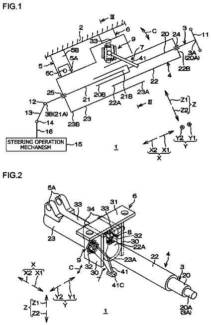
FIG. 1 is a side view schematically depicting a configuration of a steering system according to a first embodiment of the invention;
FIG. 2 is a perspective view of the steering system;
FIG. 3 is a sectional view taken along the line III-III in FIG. 1 ;
FIG. 4 is an exploded perspective view of members located near a left side plate of an upper bracket;
FIG. 5 is a sectional view taken along the line V-V in FIG. 3 ;
FIG. 6 is a sectional view taken along the line VI-VI in FIG. 3 ;
FIG. 7 is a diagram illustrating that, in FIG. 6 , a second tooth row has ridden onto a first tooth row;
FIG. 8 is a diagram illustrating that, in FIG. 5 , a released state;
FIG. 9 is a schematic diagram illustrating operations of relevant members during tilt adjustment;
FIG. 10 is a schematic diagram illustrating movement of a second restriction portion to a first tooth member;
FIG. 11 is a diagram in which a variation of the first embodiment is applied in FIG. 4 ;
FIG. 12 is an exploded perspective view of members located around a left side plate of an upper bracket of a steering system according to a second embodiment of the invention;
FIG. 13 is a schematic sectional view of a periphery of the left side plate of the upper bracket according to the second embodiment, taken along a plane perpendicular to a first linear direction;
FIG. 14 is a schematic sectional view of a periphery of a deflection suppressing structure according to a first variation of the second embodiment;
FIG. 15A is a schematic perspective view of a first tooth member according to a second variation of the second embodiment, and FIG. 15B is a schematic sectional view of the periphery of the deflection suppressing structure according to the first variation of the second embodiment;
FIG. 16 is an exploded perspective view of members located around a left side plate of an upper bracket of a steering system according to a third embodiment of the invention; and
FIG. 17 is a schematic sectional view of a periphery of the left side plate of the upper bracket according to the third embodiment, taken along a plane perpendicular to the first linear direction.
Detailed description of embodiments
An embodiment of the invention will be described below in detail with reference to the attached drawings. FIG. 1 schematically depicts a configuration of a steering system 1 according to a first embodiment of the invention. In FIG. 1 , a left side of the drawing plane corresponds to a front side of a vehicle body 2 to which the steering system 1 is attached, a right side of the drawing plane corresponds to a rear side of the vehicle body 2 , an upper side of the drawing plane corresponds to an upper side of the vehicle body 2 , and a lower side of drawing plane corresponds to a lower side of the vehicle body 2 .
As seen in FIG. 1 , the steering system 1 includes, as main components, a steering shaft 3 , a column jacket 4 , a lower bracket 5 , an upper bracket 6 (bracket). A steering member 11 is coupled to an end 3 A of the steering shaft 3 , which is a rear end. The other end 3 B of the steering shaft 3 , which is a front end, is coupled to a pinion shaft 16 of a steering operation mechanism 15 via a universal joint 12 , an intermediate shaft 13 , and a universal joint 14 in this order.
The steering operation mechanism 15 includes a rack-and-pinion mechanism. The steering operation mechanism 15 steers steered wheels such as tires not depicted in the drawings, in accordance with rotation of the steering shaft 3 transmitted to the steering operation mechanism 15 . The steering shaft 3 extends in a front-rear direction of the vehicle body 2 . A direction in which the steering shaft 3 extends is hereinafter referred to as an axial direction X. The axial direction X is inclined to a horizontal direction such that the other end 3 B located lower than the end 3 A. A rear side in the axial direction X is denoted by reference character “X 1 ”. A front side in the axial direction X is denoted by reference character “X 2 ”.
Of directions that cross the axial direction X, a direction perpendicular to the drawing sheet of FIG. 1 is referred to as a lateral direction Y (crossing direction), and a direction that is orthogonal to the axial direction X and that extends substantially in an up-down direction in FIG. 1 is referred as an up-down direction Z. In the lateral direction Y, a side facing away from the viewer in the sheet of FIG. 1 is a right side Y 1 , and a side facing the viewer in FIG. 1 is a left side Y 2 . In the up-down direction Z, an upper side is denoted by reference character “Z 1 ”, and a lower side is denoted by reference character “Z 2 ”. In the figures other than FIG. 1 , directions that correspond to the following directions are denoted by the same reference characters as those in FIG. 1 : the axial direction X, the rear side X 1 , the front side X 2 , the lateral direction Y, the right side Y 1 , the left side Y 2 , the up-down direction Z, the upper side Z 1 , and the lower side Z 2 .
The steering shaft 3 includes an upper shaft 20 that is cylindrical at least at a part of the front side X 2 of the upper shaft and a columnar lower shaft 21 . The upper shaft 20 is disposed on the rear side X 1 with respect to the lower shaft 21 and coaxially with the lower shaft 21 . A rear end 20 A of the upper shaft 20 is the end 3 A of the steering shaft 3 . A rear end portion of the lower shaft 21 is inserted into a front end portion of the upper shaft 20 from the front side X 2 . The lower shaft 21 is fitted into the upper shaft 20 by spline fitting or serration fitting. Thus, the upper shaft 20 and the lower shaft 21 are integrally rotatable and movable relative to each other along the axial direction X. The steering shaft 3 can be extended and contracted in the axial direction X by moving the upper shaft 20 with respect to the lower shaft 21 in the axial direction X.
The column jacket 4 is generally a hollow member extending in the axial direction X. The column jacket 4 houses the steering shaft 3 . The column jacket 4 has a tubular upper jacket 22 and a lower jacket 23 that extend in the axial direction X. The upper jacket 22 is positioned on the rear side X 1 with respect to the lower jacket 23 . The lower jacket 23 is externally fitted over the upper jacket 22 from the front side X 2 . In this state, the upper jacket 22 is movable with respect to the lower jacket 23 in the axial direction X. This movement enables the whole column jacket 4 to be extended and contracted along the axial direction X.
The column jacket 4 is coupled to the steering shaft 3 via a bearing 24 and a bearing 25 . Consequently, the column jacket 4 supports the steering shaft 3 so that the steering shaft 3 is rotatable, and holds the steering shaft 3 . The column jacket 4 can be extended and contracted along with the steering shaft 3 . The extension and contraction of the steering shaft 3 and the column jacket 4 as used herein are referred to as “telescopic” operations. Extension and contraction adjustment, in other words, telescopic positional adjustment of the steering member 11 in the axial direction X, is referred to as telescopic adjustment.
The lower bracket 5 supports a front side X 2 portion of the lower jacket 23 to couple the steering system 1 to the vehicle body 2 . The lower bracket 5 includes a pair of movable brackets 5 A, a fixed bracket 5 B, and a central shaft 5 C. The movable brackets 5 A are fixed to the lower jacket 23 . The fixed bracket 5 B is fixed to the vehicle body 2 . The central shaft 5 C extends in the lateral direction Y.
The movable brackets 5 A are supported by the fixed bracket 5 B so as to be able to pivot via the central shaft 5 C such as a column hinge. Thus, in conjunction with the steering shaft 3 , the column jacket 4 as a whole can pivot upward and downward around the central shaft 5 C with respect to the fixed bracket 5 B and the upper bracket 6 . The pivoting as used herein is referred to as “tilt”, and a substantial up-down direction around the central shaft 5 C is referred to as a tilt direction C. The tilt direction C extends along a trajectory K shaped like a circular arc with a predetermined curvature. The tilt direction C extends upward and downward so as to cross the axial direction X. The tilt direction C is orthogonal to the lateral direction Y. The positional adjustment of the steering member 11 based on tilting is referred to as tilt adjustment.
The upper bracket 6 supports a rear side X 1 portion of the lower jacket 23 of the column jacket 4 to couple the steering system 1 to the vehicle body 2 . As seen in FIG. 2 that is a perspective view of the steering system 1 , the upper bracket 6 is shaped like a groove that is open downward and is formed laterally symmetrically with respect to the column jacket 4 so as to appear like a general inverted U-shape as viewed in the axial direction X. Specifically, the upper bracket 6 integrally includes a pair of side plates 30 and a coupling plate 31 that is thin in the up-down direction Z. The side plates 30 are thin in the lateral direction Y and opposed to each other with the column jacket 4 located therebetween. The coupling plate 31 is coupled to an upper end of each of the side plates 30 .
The coupling plate 31 has portions that extend outward beyond the respective side plates 30 in the lateral direction Y. Bolts or the like not depicted in the drawings are inserted through the extending portions of the coupling plate 31 so that the whole upper bracket 6 is fixed to the vehicle body 2 (see FIG. 1 ). In an upper side Z 1 portion of the lower jacket 23 , a slit 33 is formed which extends all along the lower jacket 23 in the axial direction X so as to penetrate the lower jacket 23 in the up-down direction Z. At a rear end portion 23 A of the lower jacket 23 , a pair of clamped portions 34 is integrally provided which extends toward the upper side Z 1 while defining the slit 33 in the lateral direction Y. Each of the clamped portions 34 is generally a rectangular parallelepiped extending in the axial direction X and the up-down direction Z.
FIG. 3 is a sectional view taken along the line III-III in FIG. 1 . In FIG. 3 , a plane extending in the up-down direction Z through a central axis 3 C of the steering shaft 3 is referred to as a reference plane 3 D. As seen in FIG. 3 , an insertion hole 32 shaped like a rectangle that is longitudinal in the up-down direction Z is formed in each of the side plates 30 such that the insertion holes 32 are at the same position as viewed in the lateral direction Y. In each of the clamped portions 34 , a shaft insertion hole 35 is formed which penetrates the clamped portion 34 in the lateral direction Y.
In a lower side Z 2 portion of the lower jacket 23 , a guide groove 37 is formed which extends in the axial direction X. A guided protrusion 38 fixed to the upper jacket 22 is inserted through the guide groove 37 . The guide groove 37 restricts rotation of the upper jacket 22 with respect to the lower jacket 23 while guiding, via the guided protrusion 38 , movement of the upper jacket 22 in the axial direction X. An end of the guide groove 37 in the axial direction X comes into abutting contact with the guided protrusion 38 to prevent the upper jacket 22 from slipping out from the lower jacket 23 .
The steering system 1 further includes an insertion shaft 40 , an operation member 41 , a cam 42 , a first tooth member 43 , a clamping member 44 , second tooth member 45 , and an elastic member 46 . The operation member 41 is disposed near the left-side-Y 2 side plates 30 . The insertion shaft 40 is formed of metal and shaped like a rod having a central axis C 1 extending in the lateral direction Y. The insertion shaft 40 is also referred to as a tilt bolt. The insertion shaft 40 is inserted through an area where each shaft insertion hole 35 and the corresponding insertion hole 32 overlap as viewed in the lateral direction Y. Specifically, the insertion shaft 40 is inserted through the shaft insertion holes 35 so as to be rotatable around the central axis C 1 in the shaft insertion holes 35 . The insertion shaft 40 is inserted through the insertion holes 32 so as to have a clearance in the insertion holes 32 and thus to be movable in the tilt direction C in the insertion holes 32 .
The shaft insertion hole 35 restricts movement of the insertion shaft 40 in the axial direction X and the tilt direction C with respect to the column jacket 4 . The insertion shaft 40 can move in the tilt direction C in conjunction with tilting of the column jacket 4 . The insertion shaft 40 is positioned on the upper side Z 1 with respect to the steering shaft 3 . A left end portion of the insertion shaft 40 is positioned on the left side Y 2 with respect to the left-side-Y 2 side plate 30 . A right end portion of the insertion shaft is positioned on the right side Y 1 with respect to the right-side-Y 1 side plate 30 of the upper bracket 6 . At the left end portion of the insertion shaft 40 , a head portion 40 A is provided which has a larger diameter than the remaining part of the insertion shaft 40 . A thread groove 40 B is formed on an outer peripheral surface of the insertion shaft 40 at the right end portion thereof.
The operation member 41 is, for example, a lever that can be gripped. The operation member 41 includes a base end 41 A that is a longitudinal end and a gripping portion 41 B that is another longitudinal end. At the base end 41 A, an insertion hole 41 C is formed which penetrates the operation member 41 in the lateral direction Y. The insertion shaft 40 is inserted through the insertion hole 41 C. The cam 42 integrally includes an annular plate portion 42 A and a boss portion 42 B. The plate portion 42 A is located at the right side Y 1 of the base end 41 A of the operation member 41 so as to be adjacent to the base end 41 A. The boss portion 42 B extends from the plate portion 42 A toward the left side Y 2 . A cam protrusion 42 C is provided on a right side surface of the plate portion 42 A.
The insertion shaft 40 is inserted through a space defined by an inner peripheral surface of the plate portion 42 A and an inner peripheral surface of the boss portion 42 B so as to be press-fitted in the space. Thus, the cam 42 can rotate integrally with the insertion shaft 40 . The outer shape of the boss portion 42 B is generally like, for example, a quadrangle as viewed in the lateral direction Y. The boss portion 42 B is inserted through the insertion hole 41 C in the operation member 41 . This prevents the operation member 41 and the boss portion 42 B from running idly. Consequently, the operation member 41 can rotate integrally with the cam 42 and the insertion shaft 40 . As described above, the operation member 41 is attached to the left end portion of the insertion shaft 40 via the cam 42 . A driver grips and operates the gripping portion 41 B of the operation member 41 , so that the insertion shaft 40 pivots along with the operation member 41 in accordance with an operation of the operation member 41 .
FIG. 4 is an exploded perspective view of members located around the left-side-Y 2 side plate 30 of the upper bracket 6 . As seen in FIG. 4 , the first tooth member 43 is, for example, a metal plate that is elastically deformable in the lateral direction Y. An external contour of the first tooth member 43 is shaped generally like a quadrangle as viewed in the lateral direction Y.
The first tooth member 43 integrally includes a pair of support portions 49 , a pair of coupling portions 50 , and a pair of first tooth rows 51 L. The support portions 49 are shaped like plates that are longitudinal in the up-down direction Z and that are thin in the lateral direction Y. The support portions 49 are disposed away from each other in the axial direction X. Each of the support portions 49 has a plurality of holes 49 A serving as rigidity reducing portions that reduce the rigidity of the first tooth member. In each of the support portions 49 , the holes 49 A are aligned at regular intervals in the up-down direction Z. The holes 49 A penetrate the support portion 49 in the lateral direction Y. The holes 49 A in the rear-side-X 1 support portion 49 are each shaped generally like a trapezoid with an upper base facing toward the front side X 2 , as viewed in the lateral direction Y. The holes 49 A in the front-side-X 2 support portion 49 are each shaped generally like a trapezoid with an upper base facing toward the rear side X 1 , as viewed in the lateral direction Y.
The coupling portions 50 are shaped like plates that are longitudinal in the axial direction X and that are thin in the lateral direction Y. The coupling portions 50 are disposed away from each other in the up-down direction Z. The coupling portions 50 couple the support portions 49 together. Specifically, the upper-side-Z 1 coupling portion 50 is extended between upper ends of the support portions 49 . The lower-side-Z 2 coupling portion 50 is extended between lower ends of the support portions 49 .
In the first tooth member 43 , a linear slot 52 is formed which penetrates the first tooth member 43 in the lateral direction Y. The linear slot 52 extends in a first linear direction L 1 that crosses the axial direction X and that is orthogonal to the lateral direction Y. In the first embodiment, the first linear direction L 1 is a direction parallel to the up-down direction Z. The linear slot 52 is a space surrounded by the support portions 49 and the coupling portions 50 . The insertion shaft 40 is inserted through the linear slot 52 (see FIG. 3 ).
Each of the first tooth rows 51 L includes a plurality of first teeth 51 shaped generally like triangles and aligned in the first linear direction L 1 (that is also the up-down direction Z). The front-side-X 2 first tooth row 51 L is provided at a front edge of the front-side-X 2 support portion 49 . The rear-side-X 1 first tooth row 51 L is provided at a rear edge of the rear-side-X 1 support portion 49 . The first teeth 51 of the front-side-X 2 first tooth row 51 L protrude from the front-side-X 2 support portion 49 toward the front side X 2 . The first teeth 51 of the rear-side-X 1 first tooth row 51 L protrude from the rear-side-X 1 support portion 49 toward the rear side X 1 .
The first teeth 51 of each of the first tooth rows 51 L each have a tooth trace 51 A extending in the lateral direction Y. Dedendum portions 51 B of the first teeth 51 are supported by and integrated with the support portions 49 . The first tooth member 43 is elastically deformable in the lateral direction Y as described above. However, in the first tooth member 43 , at least the first tooth rows 51 L may be elastically deformable in the lateral direction Y. The first tooth member 43 is located at the left side Y 2 of the left-side-Y 2 side plate 30 so as to be adjacent to the side plate 30 (see FIG. 3 ).
In connection with the first tooth member 43 , a pair of first restriction portions 55 and a pair of recessed portions 56 are formed on the left-side-Y 2 side plate 30 of the upper bracket 6 . The first restriction portions 55 are formed by extruding the left-side-Y 2 side plate 30 . Each of the first restriction portions 55 is shaped generally like a rectangular parallelepiped that is longitudinal in a second linear direction L 2 that crosses the first linear direction L 1 and that is orthogonal to the lateral direction Y. The second linear direction L 2 is orthogonal to the first linear direction L 1 in the first embodiment. The first restriction portions 55 are integrated with the left-side-Y 2 side plate 30 . However, the first restriction portions 55 may be formed separately from and fixed to the left-side-Y 2 side plate 30 . The first restriction portions 55 are disposed away from each other in the up-down direction Z. Specifically, the respective first restriction portions 55 are disposed at an upper side and a lower side of the insertion hole 32 in the up-down direction Z.
As seen in FIG. 3 , the first tooth member 43 is disposed between the first restriction portions 55 as viewed in the axial direction X. The upper-side-Z 1 coupling portion 50 of the first tooth member 43 lies at the lower side Z 2 of the upper-side-Z 1 first restriction portion 55 so as to face the upper-side-Z 1 first restriction portion 55 . The lower-side-Z 2 coupling portion 50 of the first tooth member 43 lies at the upper side Z 1 of the lower-side-Z 2 first restriction portion 55 so as to face the lower-side-Z 2 first restriction portion 55 . Accordingly, movement of the first tooth member 43 in the up-down direction Z with respect to the left-side-Y 2 side plate 30 is restricted. The first tooth member 43 is supported by the left-side-Y 2 side plate 30 via the first restriction portions 55 so as to be movable in the second linear direction L 2 with respect to the left-side-Y 2 side plate 30 . The first restriction portions 55 extend in the second linear direction L 2 . This allows guiding movement of the first tooth member 43 in the second linear direction L 2 with respect to the left-side-Y 2 side plate 30 .
The first restriction portions 55 restrict rotation of the first tooth member 43 around the insertion shaft 40 . As seen in FIG. 4 , the left-side-Y 2 side plate 30 has peripheral portions 32 A located at opposite sides of the insertion hole 32 in the axial direction X so as to define the insertion hole 32 . Each of the recessed portions 56 is positioned outside the corresponding peripheral portion 32 A in the axial direction X. The recessed portions 56 are formed by recessing the side plate 30 toward the right side Y 1 .
The clamping member 44 integrally includes an annular plate portion 57 , a second restriction portion 58 , and a tubular boss portion 59 . The second restriction portion 58 is a block member, and the outer shape thereof is generally like a quadrangle as viewed from the right side Y 1 . The clamping member 44 includes a pressing surface 44 B constituting a right side surface of the plate portion 57 . The second restriction portion 58 extends from the pressing surface 44 B toward the right side Y 1 . The boss portion 59 extends from a right side surface of the second restriction portion 58 toward the right side Y 1 . In the clamping member 44 , a through-hole 44 A is formed which penetrates the clamping member 44 in the lateral direction Y. An internal space in the boss portion 59 forms a part of the through-hole 44 A.
As seen in FIG. 3 , the clamping member 44 is located at the right side Y 1 of the cam 42 so as to be adjacent to the cam 42 . The insertion shaft 40 is inserted through the through-hole 44 A so as to have a clearance in the through-hole 44 A. Consequently, the clamping member 44 is supported by the insertion shaft 40 so as to be rotatable relative to the insertion shaft 40 . On a left side surface of the plate portion 57 of the clamping member 44 , a cam protrusion 44 C is formed that can ride onto the cam protrusion 42 C on the cam 42 .
As seen in FIG. 4 , the second tooth member 45 is, for example, a sintered compact formed of metal. The second tooth member 45 integrally includes a main body portion 60 , a pair of protruding portions 61 , and a pair of second tooth rows 63 L. The main body portion 60 is shaped like a plate that is thin in the lateral direction Y. An external contour of the main body portion 60 is shaped generally like a rectangle that is longitudinal in the axial direction X as viewed in the lateral direction Y. Curved portions 60 A are formed at respective opposite ends, in the up-down direction Z, of a substantially central portion of the main body portion 60 in the axial direction X. The upper-side-Z 1 curved portion 60 A is bulged toward the upper side Z 1 . The lower-side-Z 2 curved portion 60 A is bulged toward the lower side Z 2 . The contour of the curved portions 60 A as viewed in the lateral direction Y has a curvature substantially equal to a circular-arc-shaped contour of the plate portion 57 of the clamping member 44 as viewed in the lateral direction Y.
Substantially at the center of the main body portion 60 in the up-down direction Z and in the axial direction X, a through-hole 45 A is formed which penetrates the main body portion 60 in the lateral direction Y. The through-hole 45 A is shaped generally like a quadrangle as viewed in the lateral direction Y. As seen in FIG. 3 , the insertion shaft 40 and the second restriction portion 58 are inserted through the through-hole 45 A. The main body portion 60 is located at the right side Y 1 of the plate portion 57 of the clamping member 44 so as to be adjacent to the plate portion 57 . The main body portion 60 lies at the left side Y 2 of the first tooth member 43 so as to be opposed to the first tooth member 43 .
As seen in FIG. 4 , the protruding portions 61 are shaped generally like rectangles that are longitudinal in the up-down direction Z as viewed in the lateral direction Y. The protruding portions 61 protrude from respective opposite ends of the main body portion 60 in the axial direction X toward the right side Y 1 . Each of the second tooth rows 63 L includes a plurality of second teeth 63 aligned along the first linear direction L 1 (that is also the up-down direction Z). One second tooth row 63 L is provided on each protruding portion 61 and thus the second tooth rows 63 L are disposed away from each other in the axial direction X. The rear-side-X 1 second tooth row 63 L protrudes from a front surface of the rear-side-X 1 protruding portion 61 toward the front side X 2 such that tooth tips 63 A of the second teeth 63 are directed toward the front side X 2 . The front-side-X 2 second tooth row 63 L protrudes from a rear surface of the front-side-X 2 protruding portion 61 toward the rear side X 1 such that direct the tooth tips 63 A of the second teeth 63 are directed toward the rear side X 1 .
The tooth tip 63 A of each of the second teeth 63 of each second tooth row 63 L has a tooth trace 63 B extending in the lateral direction Y. In each of the second tooth rows 63 L, left ends 63 C of the second teeth 63 corresponding to ends of the second teeth 63 near the main body portion 60 are fixed to a right side surface 60 B of the main body portion 60 . In each second tooth row 63 L, dedendum portions 63 D of the second teeth 63 are fixed to the protruding portion 61 . As described above, each second tooth 63 is fixed at two positions thereof, that is, at the dedendum portion 63 D and at the left end 63 C, and thus has a high strength.
The elastic member 46 is, for example, a leaf spring formed by press-molding one metal plate. The elastic member 46 integrally includes a pair of deformation portions 65 and a pair of coupling portions 66 . The deformation portions are disposed away from each other in the axial direction X. The coupling portions 66 are disposed away from each other in the up-down direction Z. The deformation portions 65 are thin in the lateral direction Y and are longitudinal in the up-down direction Z. A substantial center of each of the deformation portions 65 in the up-down direction Z is curved so as to bulge toward the left side Y 2 . The deformation portions 65 are elastically deformable in the lateral direction Y. On each of opposite ends of each deformation portion 65 in the up-down direction Z, a hook portion 67 is formed which is bent toward the left side Y 2 like a crank.
Each of the hook portions 67 integrally includes a first portion 67 A and a second portion 67 B that is thin in the up-down direction Z. The first portion 67 A is thin in the lateral direction Y and extends in the up-down direction Z. The second portion 67 B is thin in the up-down direction Z and extends from a tip of the first portion 67 A toward the left side Y 2 . The second portion 67 B of each upper-side-Z 1 hook portion 67 extends from an upper end of the first portion 67 A. The second portion 67 B of each lower-side-Z 2 hook portion 67 extends from a lower end of the first portion 67 A.
The coupling portions 66 of the elastic member 46 are thin in the lateral direction Y and are longitudinal in the axial direction X. The upper-side-Z 1 coupling portion 66 is extended between upper ends of the deformation portions 65 . The lower-side-Z 2 coupling portion 67 is extended between lower ends of the deformation portions 65 . A space 46 A defined by the deformation portions 65 and the coupling portions 66 is shaped generally like a quadrangle that is substantially equal in shape to the through-hole 45 A as viewed in the lateral direction Y.
As seen in FIG. 3 , the elastic member 46 is located at the right side Y 1 of the second tooth member 45 so as to be adjacent to the second tooth member 45 . The elastic member 46 is located at the left side Y 2 of the first tooth member 43 so as to be adjacent to the first tooth member 43 . The insertion shaft 40 and the second restriction portion 58 are inserted through the space 46 A. The second portions 67 B of the upper-side-Z 1 hook portions 67 of the elastic member 46 lie at the upper side Z 1 of the main body portion 60 of the second tooth member 45 so as to engage with the main body portion 60 . The second portions 67 B of the lower-side-Z 2 hook portions 67 of the elastic member 46 lie at the lower side Z 2 of the main body portion 60 of the second tooth member 45 so as to engage with the main body portion 60 . Consequently, the elastic member 46 is integrated with the second tooth member 45 .
FIG. 5 is a sectional view taken along the line V-V in FIG. 3 . As seen in FIG. 5 , the second restriction portion 58 of the clamping member 44 is inserted through the through-hole 45 A in the second tooth member 45 , the space 46 A in the elastic member 46 , and the linear slot 52 in the first tooth member 43 in this order from the left side Y 2 . As described above, the insertion shaft 40 is inserted through the through-hole 44 A in the clamping member 44 . Consequently, the second tooth member 45 and the elastic member 46 are supported by the insertion shaft 40 via the clamping member 44 . As described above, the through-hole 45 A, the space 46 A, and the second restriction portion 58 are each shaped generally like a quadrangle as viewed in the lateral direction Y. Thus, the second tooth member 45 and the elastic member 46 are prevented from running idly with respect to the second restriction portion 58 . The second restriction portion 58 is coupled to the second tooth member 45 .
A clearance between the second restriction portion 58 and each of the opposite ends of the linear slot 52 in the axial direction X is slight and only enough to allow the second restriction portion 58 to move in the up-down direction Z along and relative to the linear slot 52 . Thus, the second restriction portion 58 is movable in the first linear direction L 1 with respect to the linear slot 52 and is immovable in the second linear direction L 2 with respect to the linear slot 52 . This restricts movement of the second tooth member 45 in the second linear direction L 2 with respect to the first tooth member 43 .
Idle running of the clamping member 44 with respect to the first tooth member 43 is prevented by contact between opposite end surfaces of the second restriction portion 58 in the axial direction X and opposite edges of the linear slot 52 in the axial direction X. As described above, rotation of the first tooth member 43 around the insertion shaft 40 is restricted by the first restriction portions 55 . This restricts rotation, around the insertion shaft 40 , of the clamping member 44 , the second tooth member 45 , and the elastic member 46 . Idle running of the clamping member 44 with respect to the first tooth member 43 is prevented. Idle running of the second tooth member 45 with respect to the second restriction portion 58 of the clamping member 44 is prevented.
A right end of the second restriction portion 58 of the clamping member 44 and the whole boss portion 59 are inserted through the insertion hole 32 so as to have a clearance in the insertion hole 32 . A bottom surface 56 A of each recessed portion 56 lies at the right side Y 1 of the corresponding first tooth row 51 L so as to face the first tooth row 51 L. The peripheral portions 32 A of the insertion hole 32 sandwich the support portions 49 of the first tooth member 43 , the deformation portions 65 of the elastic member 46 , and the main body portion 60 of the second tooth member 45 between the peripheral portions 32 A and the pressing surface 44 B of the clamping member 44 , and is located on the right side of the right side of the clamping member 44 . The peripheral portions 32 A lie at the right side Y 1 of the pressing surface 44 B of the clamping member 44 so as to face the pressing surface 44 B. The deformation portions 65 of the elastic member 46 are compressed in the lateral direction Y between the main body portion 60 of the second tooth member 45 and the support portions 49 of the first tooth member 43 .
As seen in FIG. 3 , the cam 42 rotates in accordance with an operation of the operation member 41 to allow the cam protrusion 42 C rides onto the cam protrusion 44 C. Consequently, the clamping member 44 moves in the lateral direction Y along the central axis C 1 . The second tooth member 45 is located at the right side Y 1 of the plate portion 57 of the clamping member 44 so as to be adjacent to the plate portion 57 . Thus, the second tooth member 45 moves toward the right side Y 1 in conjunction with movement of the clamping member 44 toward the right side Y 1 .
The steering system 1 includes a first tooth member 71 , a second tooth member 72 , an elastic member 73 , a nut 74 , a needle roller bearing 75 , and a thrust washer 76 . The first tooth member 71 is disposed near the right-side-Y 1 side plate 30 . The first tooth member 71 , the second tooth member 72 , and the elastic member 73 on the right side Y 1 are obtained by inverting the first tooth member 43 , the second tooth member 45 , and the elastic member 46 on the left side Y 2 , respectively, with respect to the reference plane 3 D. The right-side-Y 1 side plate 30 is provided with a pair of first restriction portions 77 and a pair of recessed portions 78 . The first restriction portions 77 and the recessed portions 78 are obtained by inverting the first restriction portions 55 and the recessed portions 56 formed on the left-side-Y 2 side plate 30 with respect to the reference plane 3 D.
The description continues in the full USPTO document.
 Lapsed, fee not paid10 drawings