Lapsed, fee not paid2 drawings
Medical Devices · US 8,738,125 B1
Devices and methods for delivering molecules to the heart with electric fields
A device and related methodologies to deliver molecules to the cells that comprise any tissues.
US 8,738,148 B2 · Assignee: Medtronic, Inc. · Inventors: Olson; David P. et al.
Sheet 1 of 16 from the published document. All sheets in the USPTO PDF
System for transcutaneous energy transfer. An implantable medical device, adapted to be implanted in a patient, has componentry for providing a therapeutic output. The implantable medical device has an internal power source and a secondary coil operatively coupled to the internal power source. An external power source, having a primary coil, provides energy to the implantable medical device when the primary coil of the external power source is placed in proximity of the secondary coil of the implantable medical device and thereby generates a current in the internal power source. An alignment indicator reports the alignment as a function of the current generated in the internal power source with a predetermined value associated with an expected alignment between the primary coil and secondary coil.
Implantable medical devices for producing a therapeutic result in a patient are well known. Examples of such implantable medical devices include implantable drug infusion pumps, implantable neurostimulators, implantable cardioverters, implantable cardiac pacemakers, implantable defibrillators and cochlear implants. Of course, it is recognized that other implantable medical devices are envisioned which utilize energy delivered or transferred from an external device. A common element in all of these implantable medical devices is the need for electrical power in the implanted medical device. The implanted medical device requires electrical power to perform its therapeutic function whether it be driving an electrical infusion pump, providing an electrical neurostimulation pulse or providing an electrical cardiac stimulation pulse. This electrical power is derived from a power source. Typica
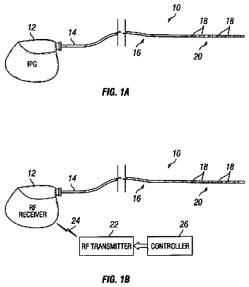
1 of 16 drawing sheets so far from the published document, cropped to the drawing. Every sheet is in the USPTO PDF.
What the patent claimed, word for word. All of it is now free to use.
This invention relates to implantable medical devices and, in particular, to energy transfer devices, systems and methods for implantable medical devices.
Implantable medical devices for producing a therapeutic result in a patient are well known. Examples of such implantable medical devices include implantable drug infusion pumps, implantable neurostimulators, implantable cardioverters, implantable cardiac pacemakers, implantable defibrillators and cochlear implants. Of course, it is recognized that other implantable medical devices are envisioned which utilize energy delivered or transferred from an external device.
A common element in all of these implantable medical devices is the need for electrical power in the implanted medical device. The implanted medical device requires electrical power to perform its therapeutic function whether it be driving an electrical infusion pump, providing an electrical neurostimulation pulse or providing an electrical cardiac stimulation pulse. This electrical power is derived from a power source.
Typically, a power source for an implantable medical device can take one of two forms. The first form utilizes an external power source that transcutaneously delivers energy via wires or radio frequency energy. Having electrical wires which perforate the skin is disadvantageous due, in part, to the risk of infection. Further, continuously coupling patients to an external power for therapy is, at least, a large inconvenience. The second form utilizes single cell batteries as the source of energy of the implantable medical device. This can be effective for low power applications, such as pacing devices. However, such single cell batteries usually do not supply the lasting power required to perform new therapies in newer implantable medical devices. In some cases, such as an implantable artificial heart, a single cell battery might last the patient only a few hours. In other, less extreme cases, a single cell unit might expel all or nearly all of its energy in less than a year. This is not desirable due to the need to explant and re-implant the implantable medical device or a portion of the device. One solution is for electrical power to be transcutaneously transferred through the use of inductive coupling. Such electrical power or energy can optionally be stored in a rechargeable battery. In this form, an internal power source, such as a battery, can be used for direct electrical power to the implanted medical device. When the battery has expended, or nearly expended, its capacity, the battery can be recharged transcutaneously, via inductive coupling from an external power source temporarily positioned on the surface of the skin.
Several systems and methods have been used for transcutaneously inductively recharging a rechargeable used in an implantable medical device.
PCT Patent Application No. WO 01/83029 A1, Torgerson et al, Battery Recharge Management For an Implantable Medical Device, (Medtronic, Inc.) discloses an implantable medical device having an implantable power source such as a rechargeable lithium ion battery. The implantable medical device includes a recharge module that regulates the recharging process of the implantable power source using closed-loop feedback control. The recharging module includes a recharge regulator, a recharge measurement device monitoring at least one recharge parameter, and a recharge regulation control unit for regulating the recharge energy delivered to the power source in response to the recharge measurement device. The recharge module adjusts the energy provided to the power source to ensure that the power source is being recharged under safe levels.
Transcutaneous energy transfer through the use of inductive coupling involves the placement of two coils positioned in close proximity to each other on opposite sides of the cutaneous boundary. The internal coil, or secondary coil, is part of or otherwise electrically associated with the implanted medical device. The external coil, or primary coil, is associated with the external power source or external charger, or recharger. The primary coil is driven with an alternating current. A current is induced in the secondary coil through inductive coupling. This current can then be used to power the implanted medical device or to charge, or recharge, an internal power source, or a combination of the two.
U.S. Pat. No. 5,713,939, Nedungadi et al, Data Communication System For Control of Transcutaneous Energy Transmission To an Implantable Medical Device, discloses a data communication system for control of transcutaneous energy transmission to an implantable medical device. The implantable medical device has rechargeable batteries and a single coil that is employed both for energy transmission and data telemetry. Control circuitry in the implantable device senses battery voltage and current through the battery, encodes those values by the use of multiplexer, and transmits the sensed and encoded values through the coil to an external energy transmission device. The external device includes a coil that is electromagnetically coupled to the coil in the implantable device for receiving the encoded signals and for transmitting energy to the implantable device. The external device decodes the transmitted values and transmits those to a controller for controlling energy transmission.
U.S. Pat. No. 6,212,431, Hahn et al, Power Transfer Circuit For Implanted Devices, discloses an external power transfer circuit which couples ac power having a fixed frequency into an implantable electrical circuit, e.g., an implantable tissue stimulator, while automatically maintaining optimum power transfer conditions. Optimum power transfer conditions exist when there is an impedance match between the external and implanted circuits. The external transfer circuit includes a directional coupler and an impedance matching circuit. The directional coupler senses the forward power being transferred to the implant device, as well as the reverse power being reflected form the implant device (as a result of an impedance mismatch). The impedance matching circuit includes at least one variable element controlled by a control signal. The sensed reverse power is used as a feedback signal to automatically adjust the variable element in the impedance matching circuit, and hence the output impedance of the external power transfer circuit, so that it matches the input impedance of the implant device, despite variations that occur in the input impedance of the implant device due to variations in implant distance and implant load.
For implanted medical devices, the efficiency at which energy is transcutaneously transferred is crucial. First, the inductive coupling, while inductively inducing a current in the secondary coil, also has a tendency to heat surrounding components and tissue. The amount of heating of surrounding tissue, if excessive, can be deleterious. Since heating of surrounding tissue is limited, so also is the amount of energy transfer which can be accomplished per unit time. The higher the efficiency of energy transfer, the more energy can be transferred while at the same time limiting the heating of surrounding components and tissue. Second, it is desirable to limit the amount of time required to achieve a desired charge, or recharge, of an internal power source. While charging, or recharging, is occurring the patient necessarily has an external encumbrance attached to their body. This attachment may impair the patient's mobility and limit the patient's comfort. The higher the efficiency of the energy transfer system, the faster the desired charging, or recharging, can be accomplished limiting the inconvenience to the patient. Third, amount of charging, or recharging, can be limited by the amount of time required for charging, or recharging. Since the patient is typically inconvenienced during such charging, or recharging, there is a practical limit on the amount of time during which charging, or recharging, should occur. Hence, the size of the internal power source can be effectively limited by the amount of energy which can be transferred within the amount of charging time. The higher the efficiency of the energy transfer system, the greater amount of energy which can be transferred and, hence, the greater the practical size of the internal power source. This allows the use of implantable medical devices having higher power use requirements and providing greater therapeutic advantage to the patient and/or extends the time between charging effectively increasing patient comfort.
Alignment of an external primary coil with the internal secondary coil is important in achieving efficiency in transcutaneous energy transfer. However, it is not always easy for the user to know when the primary and secondary coils are properly aligned. Often the user must resort to tactile information gleaned from the physical package into which the primary coil is located and a subtle protrusion under the skin approximately where the implantable medical device has been implanted. However, even perfectly aligning the physical package containing the primary coil with the protrusion of the implanted medical device may not result in optimum alignment of the primary and secondary coils. Often the primary coil or the secondary coil, or both, is not centered in the physical packages within which they are contained. Thus, even perfect alignment of the packages may result in actual misalignment of the primary and secondary coils.
Various aspects of the present invention provide a system for transcutaneous energy transfer, external power system for transcutaneous energy transfer or a method for indicating alignment between an external primary coil and an implanted secondary coil. Alternatively, the present invention provides a system for transcutaneous energy transfer having an external power source which varies its power output in order to generate a predetermined current in the internal power source, which can be a function of alignment between the coils, without actually indicating alignment to a user or other person, e.g., a medical professional assisting or performing the transcutaneous energy transfer.
In one embodiment, the present invention provides a system for transcutaneous energy transfer. An implantable medical device, adapted to be implanted in a patient, has componentry for providing a therapeutic output. The implantable medical device has an internal power source and a secondary coil operatively coupled to the internal power source. An external power source, having a primary coil, provides energy to the implantable medical device when the primary coil of the external power source is placed in proximity of the secondary coil of the implantable medical device and thereby generates a current in the internal power source. An alignment indicator reports the alignment as a function of the current generated in the internal power source with a predetermined value associated with an expected alignment between the primary coil and secondary coil.
In a preferred embodiment, the alignment indicator ceases reporting of the alignment following reaching a predetermined point of a charging cycle.
In a preferred embodiment, the predetermined point of a charging cycle comprises following the internal power source reaching a predetermined voltage.
In a preferred embodiment, the predetermined voltage is at least ninety percent of a voltage representing an expected full charge of the internal power source.
In a preferred embodiment, the external power source varies its power output in order to generate a predetermined current in the internal power source.
In another embodiment, the present invention provides an external power system for transcutaneous energy transfer to an implantable medical device, implantable medical device adapted to be implanted in a patient, having componentry for providing a therapeutic output and a secondary coil operatively coupled to the componentry. A primary coil provides energy to the implantable medical device when the primary coil is placed in proximity of the secondary coil of the implantable medical device and thereby generates a current in the internal power source. An alignment indicator reports the alignment as a function of the current generated in the internal power source with a predetermined value associated with an expected alignment between the primary coil and secondary coil.
In a preferred embodiment, the internal power source has an internal impedance and wherein the predetermined value is adjusted as a function of the internal impedance of the internal power source.
In a preferred embodiment, the internal power has a voltage and wherein the predetermined value is adjusted as a function of the voltage of the internal power source.
In a preferred embodiment, the predetermined value decreases as the voltage of the power source decreases.
In a preferred embodiment, the alignment indicator comprises a display.
In a preferred embodiment, the display comprises a percentage of the current generated in the secondary coil to the predetermined value.
In a preferred embodiment, the display comprises a bar graph.
In a preferred embodiment, the expected alignment comprises perfect alignment.
In another embodiment, the present invention provides a system for transcutaneous energy transfer. An implantable medical device, adapted to be implanted in a patient, has componentry for providing a therapeutic output, an internal power source and a secondary coil operatively coupled to the internal power source, the implantable medical device. An external power source, having a primary coil, provides energy to the implantable medical device when the primary coil of the external power source is placed in proximity of the secondary coil of the implantable medical device and thereby generates a current in the internal power source. The external power source varies its power output in order to generate a predetermined current in the internal power source.
In a preferred embodiment, the predetermined current in the internal power source varies as a function of the voltage of the internal power source.
In another embodiment, the present invention provides a method of indicating an alignment between an external primary coil and an inductively coupled secondary coil of an implanted medical device, the secondary coil supplying power to a power source having an internal impedance. The external primary coil is driven with a charging signal. A current generated in the power source by the charging signal is measured. An amount of the current generated in the power source is compared with a predetermined value associated with an expected alignment between the external primary coil and the secondary coil. An amount of the current generated in the power source is compared with a predetermined value. The alignment is reported as a function of the current generated in the secondary coil with the predetermined value from the comparison step. The predetermined value is adjusted as a function of the internal impedance of the power source.
In a preferred embodiment, the steps are repeated as the voltage of the power source declines.
In a preferred embodiment, the power source is a battery.
In a preferred embodiment, the comparing step determines a percentage of the current generated in the secondary coil to the predetermined value.
In a preferred embodiment, the reporting step comprises displaying the percentage.
In a preferred embodiment, the displaying step comprises displaying some of a plurality of steps in a bar graph.
In a preferred embodiment, the displaying step displays perfect alignment when the percentage is one hundred percent.
In a preferred embodiment, the internal impedance of the power source increases over time.
In a preferred embodiment, a power output of the external power source is varied in order to generate a predetermined current in the internal power source.
In another embodiment, the present invention provides a method of transcutaneous energy transfer between an external primary coil and an inductively coupled secondary coil of an implanted medical device. The secondary coil supplies power to a power source having an internal impedance. The external primary coil is driven with a charging signal. A current generated in the power by the charging signal is measured. The charging signal is varied in order to generate a predetermined current in the internal power source.
In a preferred embodiment, the method additionally varies the predetermined current in the internal power source as a function of the voltage of the internal power source.
In a preferred embodiment, the predetermined current in the internal power source declines as the voltage of the internal power source increases during a charging cycle.
In a preferred embodiment, the predetermined current in the internal power source comprises a maximum amount current for charging the internal power source.
In a preferred embodiment, the predetermined current in the internal power source declines over time as the internal impedance of the internal power source increases.
FIG. 1 illustrates an implantable medical device implanted in a patient;
FIG. 2 is a block diagram of an implantable medical device;
FIG. 3 is a detailed block diagram of an implantable medical device implanted subcutaneously and an associated external charging device in accordance with an embodiment of the present invention;
FIG. 4 is a perspective view of an internal antenna associated with an implantable medical device;
FIG. 5 is a side view of the internal antenna of FIG. 4;
FIG. 6 is an exploded perspective view an external antenna and associated bracket in accordance with an embodiment of the present invention;
FIG. 7 is a top view of an external antenna in accordance with an embodiment of the present invention;
FIG. 8 is a perspective view of an external antenna and bracket combination in accordance with an embodiment of the present invention;
FIG. 9 is a cross-sectional side view of an implantable medical device implanted subcutaneously and an associated bracket for use with an external antenna;
FIG. 10 is a cut-away top view of view a primary coil and associated magnetic core in accordance with an embodiment of the present invention;
FIG. 11 is a cross-sectional view of the primary coil and associated magnetic core of FIG. 10 taken through section line B-B;
FIG. 12 is an exploded view a portion of an external antenna constructed in accordance with an embodiment of the present invention showing the magnetic core and a core cup assembly;
FIG. 13 is block diagram of an external charging unit and an associated inductively coupled cradle for recharging the external charging unit;
FIG. 14 is a detailed block diagram of the external charging unit of FIG. 13;
FIG. 15 is a flow chart illustrating a charging process in accordance with an embodiment of the present invention;
FIG. 16 is a schematic diagram of a dual range temperature sensor;
FIG. 17 is a block diagram of an alignment indicator;
FIG. 18 is a diagram of a display for the alignment indicator of FIG. 17; and
FIG. 19 is a flow chart illustrating charging of an implantable medical device.
The entire content of U.S. patent application Ser. No. 13/210,852, filed Aug. 16, 2011, U.S. patent application Ser. No. 12/827,304, filed Jun. 30, 2010, now U.S. Pat. No. 8,024,047, and U.S. patent application Ser. No. 11/119,361, filed Apr. 29, 2005, now U.S. Pat. No. 7,774,069, are hereby incorporated by reference.
FIG. 1 shows implantable medical device 16, for example, a drug pump, implanted in patient 18. The implantable medical device 16 is typically implanted by a surgeon in a sterile surgical procedure performed under local, regional, or general anesthesia. Before implanting the medical device 16, a catheter 22 is typically implanted with the distal end position at a desired therapeutic delivery site 23 and the proximal end tunneled under the skin to the location where the medical device 16 is to be implanted. Implantable medical device 16 is generally implanted subcutaneously at depths, depending upon application and device 16, of from 1 centimeter (0.4 inches) to 2.5 centimeters (1 inch) where there is sufficient tissue to support the implanted system. Once medical device 16 is implanted into the patient 18, the incision can be sutured closed and medical device 16 can begin operation.
Implantable medical device 16 operates to infuse a therapeutic substance into patient 18. Implantable medical device 16 can be used for a wide variety of therapies such as pain, spasticity, cancer, and many other medical conditions.
The therapeutic substance contained in implantable medical device 16 is a substance intended to have a therapeutic effect such as pharmaceutical compositions, genetic materials, biologics, and other substances. Pharmaceutical compositions are chemical formulations intended to have a therapeutic effect such as intrathecal antispasmodics, pain medications, chemotherapeutic agents, and the like. Pharmaceutical compositions are often configured to function in an implanted environment with characteristics such as stability at body temperature to retain therapeutic qualities, concentration to reduce the frequency of replenishment, and the like. Genetic materials are substances intended to have a direct or indirect genetic therapeutic effect such as genetic vectors, genetic regulator elements, genetic structural elements, DNA, and the like. Biologics are substances that are living matter or derived from living matter intended to have a therapeutic effect such as stem cells, platelets, hormones, biologically produced chemicals, and the like. Other substances may or may not be intended to have a therapeutic effect and are not easily classified such as saline solution, fluoroscopy agents, disease diagnostic agents and the like. Unless otherwise noted in the following paragraphs, a drug is synonymous with any therapeutic, diagnostic, or other substance that is delivered by the implantable infusion device.
Implantable medical device 16 can be any of a number of medical devices such as an implantable therapeutic substance delivery device, implantable drug pump, cardiac pacemaker, cardioverter or defibrillator, as examples.
In FIG. 2, implantable medical device 16 has a rechargeable power source 24, such as a Lithium ion battery, powering electronics 26 and therapy module 28 in a conventional manner. Therapy module 28 is coupled to patient 18 through one or more therapy connections 30, also conventionally. Rechargeable power source 24, electronics 26 and therapy module 28 are contained in hermetically sealed housing 32. Secondary charging coil 34 is attached to the exterior of housing 32. Secondary charging coil 34 is operatively coupled through electronics 26 to rechargeable power source 24. In an alternative embodiment, secondary charging coil 34 could be contained in housing 32 or could be contained in a separate housing umbilically connected to electronics 26. Electronics 26 help provide control of the charging rate of rechargeable power source 24 in a conventional manner. Magnetic shield 36 is positioned between secondary charging coil 34 and housing 32 in order to protect rechargeable power source 24, electronics 26 and therapy module 28 from electromagnetic energy when secondary charging coil 34 is utilized to charge rechargeable power source 24.
Rechargeable power source 24 can be any of a variety power sources including a chemically based battery or a capacitor. Rechargeable power source may be a well known lithium ion battery.
FIG. 3 illustrates an alternative embodiment of implantable medical device 16 situated under cutaneous boundary 38. Implantable medical device 16 is similar to the embodiment illustrated in FIG. 2. However, charging regulation module 42 is shown separate from electronics 26 controlling therapy module 28. Again, charging regulation and therapy control is conventional. Implantable medical device 16 also has internal telemetry coil 44 configured in conventional manner to communicate through external telemetry coil 46 to an external programming device (not shown), charging unit 50 or other device in a conventional manner in order to both program and control implantable medical device and to externally obtain information from implantable medical device 16 once implantable medical device has been implanted. Internal telemetry coil 44, rectangular in shape with dimensions of 1.85 inches (4.7 centimeters) by 1.89 inches (4.8 centimeters) constructed from 150 turns of 43 AWG wire, is sized to be larger than the diameter of secondary charging coil 34. Secondary coil 34 is constructed with 182 turns of 30 AWG wire with an inside diameter of 0.72 inches (1.83 centimeters) and an outside diameter of 1.43 inches (3.63 centimeters) with a height of 0.075 inches (0.19 centimeters). Magnetic shield 36 is positioned between secondary charging coil 34 and housing 32 and sized to cover the footprint of secondary charging coil 34.
Internal telemetry coil 44, having a larger diameter than secondary coil 34, is not completely covered by magnetic shield 36 allowing implantable medical device 16 to communicate with the external programming device with internal telemetry coil 44 in spite of the presence of magnetic shield 36.
Rechargeable power source 24 can be charged while implantable medical device 16 is in place in a patient through the use of external charging device 48. In an embodiment, external charging device 48 consists of charging unit 50 and external antenna 52. Charging unit 50 contains the electronics necessary to drive primary coil 54 with an oscillating current in order to induce current in secondary coil 34 when primary coil 54 is placed in the proximity of secondary coil 34. Charging unit 50 is operatively coupled to primary coil by cable 56. In an alternative embodiment, charging unit 50 and antenna 52 may be combined into a single unit. Antenna 52 may also optionally contain external telemetry coil 46 which may be operatively coupled to charging unit 50 if it is desired to communicate to or from implantable medical device 16 with external charging device 48. Alternatively, antenna 52 may optionally contain external telemetry coil 46 which can be operatively coupled to an external programming device, either individually or together with external charging unit 48.
As will be explained in more detail below, repositionable magnetic core 58 can help to focus electromagnetic energy from primary coil 46 to more closely be aligned with secondary coil 34. Also as will be explained in more detail below, energy absorptive material 60 can help to absorb heat build-up in external antenna 52 which will also help allow for a lower temperature in implantable medical device 16 and/or help lower recharge times. Also as will be explained in more detail below, thermally conductive material 62 is positioned covering at least a portion of the surface of external antenna 52 which contacts cutaneous boundary 38 of patient 18.
As shown in FIG. 4 and FIG. 5, secondary coil 34 and magnetic shield 36 are separate from but adjacent to housing 32 encompassing the remainder of implantable medical device 16. Internal antenna 68 is contained in a separate housing 74 which is attachable to housing 32 so that implantable medical device 16 can be implanted by a medical professional as essentially one unit. Secondary coil 34 is electrically attached to charging regulation module 42 through leads 82.
In order to achieve efficient inductive coupling between primary coil 54 of external antenna 52 and secondary coil 34, it is desirable to place primary coil 54 of external antenna 52 as close to secondary coil 34 as possible. Typically, external antenna 52 is placed directly on cutaneous boundary 38 and, since the location of implantable medical device 16 is fixed, the distance across cutaneous boundary 38 between primary coil 54 and secondary coil 34 is minimized as long as external antenna 52 is kept adjacent cutaneous boundary 38.
External antenna 52 is attachable to patient 18 with bracket 84 when charging rechargeable power source 24. FIG. 6 is an exploded illustration of an embodiment of external antenna 52 attachable to bracket 84. Primary coil 54 is contained in bobbin assembly 86 which sits in bottom housing 88. Primary coil is connectable to cable 56. The bottom of external antenna 52 is formed from a thermally conductive material 90. Rotating core cup assembly 92 is held in place by top housing 94. Rotating core cup assembly 92 is rotatable is allowed to rotate within external antenna 52. Detents 96 engage detent spring 98 to position rotatable core cup assembly 92 in one of a plurality of detent positions. External antenna may be secured together, for example, with screws (not shown) holding top housing 94 and thermally conductive material 90 together.
Bracket 84 is adapted to be attached to the body of patient 18 with a belt (not shown) attachable to bracket 84 with belt loops 102. Ears 104 are adapted to mate with tabs 106 in top housing 94 and pivotally secure external antenna 52 in bracket 84 when charging is to be accomplished. Bracket 84 has an opening 108 allowing thermally conductive material 90 of external antenna 52 to contact the skin of patient 18 when external antenna 52 is pivotally secured in bracket 84.
As bracket 84 is attached to patient 18 with a belt via belt loops 102, the skin surface of patient 18 is typically not completely flat. For example, if implantable medical device 16 is implantable in the body torso of patient 18, then the belt attached via belt loops 102 will typically pass around the torso of patient 18. Since the torso of patient 18, and especially the torso of patient 18 near the location of implantable medical device 16, bracket 84 may not sit completely flat on patient 18. This may be especially true as patient 18 moves and the torso flexes during such movement. Bracket 84 may be conformal and flexible in order to conform to the shape of the body of patient 18. However, bracket 84 may also be rigid enough so that opening 108 in bracket 84 maintains its shape in order to properly receive external antenna 52. Bracket 84 is preferably constructed of PCABS. To maintain the proper position of bracket 84 with the skin of patient 18, the surface of bracket 84 closest to patient 18 contains material 109 constructed from a high durometer, e.g., 40 Shore A, or "sticky" material such as a material known under the trade name of "Versaflex" manufactured by GLS Corp. of McHenry, Ill. This will help external antenna to sit more closely to the skin surface of patient 18 and remain there during movements of patient 18 throughout the charge or recharge cycle. In addition, external antenna 52 is allowed to pivot by way of ears 104 on tabs 106. Bracket 84 is configured to allow thermally conductive material 90 to extend through opening 108 and contact the skin surface of patient 18. Allowed pivoting of external antenna 52 and, hence, thermally conductive material 90, permits thermally conductive surface to sit more closely to the skin surface of patient 18.
FIG. 7 is a partially cut away top view of external antenna 52 in assembled form and attached to cable 56. Rotatable core cup assembly 92 is shown located inside of primary coil 54 and positionable in selected rotated positions via detents 96 and detent spring 98. In FIG. 7, rotatable core cup assembly is positioned between with detent spring 98 between detents 96 illustrating that while multiple detent positions are available, rotatable core cup assembly can be positioned between detent positions and, indeed, at any rotated position.
In FIG. 8, the assembly of external antenna 52 with bracket 84 is shown connected to cable 56. Bracket 84 may be affixed to patient 18 through belt loops 102 and then, after bracket 84 has been affixed to patient 18, external antenna 52 be attached to bracket 84. Affixing bracket 84 to patient 18 first allows for bracket 84 to be used to laterally position external antenna close to the position of implantable medical device 16.
Typical prior art positioning systems rely on the external antenna for lateral positioning. The external antenna is moved around on the body of the patient 18 until the best lateral position is found. When the best lateral position is found, the external antenna is removed from the body and the bottom of the external antenna (the portion of the external antenna) contacting the patient's body) is made to be resistant to lateral movement. As an example, one way is to remove a protective liner exposing a sticky surface allowing the external antenna to be relatively fixed in location. However, the very act of lifting the external antenna in order to remove the protective liner and replacing the external antenna on the body of the patient 18 causes crucial positioning information to be lost. There is no guarantee, and in fact it is not likely, that the external antenna will be replaced in the exact same position as the position previously found to be best.
In contrast, bracket 84 of the present invention can be used to roughly find the optimum position for external antenna 52. This can be done relatively easily due to opening 108 in bracket 84. Implantable medical device 16, when implanted, usually leaves an area of the body of patient 18 which is not quite as flat as it was before implantation. That is, implantable medical device 16 usually leaves an area of the skin of patient 18 which bulges somewhat to accommodate the bulk of implantable medical device 16. It is relatively easy for patient, medical professional or other person, to place bracket 84 in the general area of implantable medical device 16 and move bracket 84 around until the bulge caused by implantable medical device 16 is most closely centered in opening 108. As bracket 84 is moved laterally, opening 108 tends to naturally center on the bulge created by implantable medical device 16. Once positioned in this manner, bracket 84 can be secured to the body of patient 18 with belt (not shown) attached via belt loops 102. Securing and/or tightening, by pulling the belt tight or snapping a buckle, for example, can be without removing bracket 84 from the body of patient 16. Thus, bracket 84 can be relatively easily positioned over the general location of implantable medical device 16 and secured in that position without being removed from the body of patient 18.
FIG. 9 is cross-sectional view of implantable medical device 16 implanted in patient 18 approximately one centimeter under cutaneous boundary 38 creating bulging area 110, an area of the body of patient 18 in which the skin of patient 18 is caused to bulge slightly due to the implantation of implantable medical device 16. Bulging area 110 is an aid to locating the position of external antenna 52 relative to secondary coil 34. Bracket 84 can be positioned roughly in the area where implantable medical device 16 is implanted. Opening 108 in bracket 84 can aid in establishing the location of implantable medical device. Bracket 84 can be roughly centered over bulging area 110. After external antenna 52 is coupled to bracket 84, then primary coil 54 can be generally centered on implantable medical device 16.
However, secondary coil 34 may not be centered with respect to implantable medical device 16. This can occur due to a variety of reasons such as the need for operatively coupling secondary coil 34 to charging regulation module 42. Connections to make this operative coupling may require physical space on one side of internal antenna 68 which may cause secondary coil 34 not to be centered on implantable medical device 16. It is also possible that the attachment of internal antenna 68 to housing 32 can cause secondary coil 34 not to be centered on implantable medical device 16. Regardless of the cause, if secondary coil 34 is not centered on implantable medical device 16, then centering bracket 84 on bulging area 110 may not optimally position primary coil 54 with respect to secondary coil 34. Any offset in the position of primary coil 54 and secondary coil 34 may not result in the most efficient energy transfer from external antenna 52 to implantable medical device 16.
A magnetic core 58 is positioned within primary coil 54 in order to focus energy generated by primary coil 54. Magnetic core 58 attracts the magnetic flux lines generated by primary coil 54. The position of magnetic core 58 within primary coil 54 determines the lateral location of the largest amount of the flux lines generated by primary coil 54. FIGS. 10 and 11 show cut-away top and cross-sectional views of magnetic core 58 used with primary coil 54. Magnetic core 58 is moveable within primary coil 54. Lower portion 122 of magnetic core 58 can be rotated to a plurality of positions within primary coil 58 by rotating core cup assembly 92 (see FIG. 12). The travel path of magnetic core 58 can be locked in a plurality of discrete positions. Magnetic core 58 may be locked in four
different positions by detents 96 and detent spring 98 (see FIG. 6). Magnetic core 58 has an upper planar portion 120 and a smaller lower portion 122.
As magnetic core 58 is repositioned within primary coil 54, the focus of magnetic flux generated by primary coil 54 is also repositioned. As noted above, external antenna 52 is generally aligned with implanted medical device 16 using palpatory sensation. Moveable magnetic core 58 can then be used to provide a "fine" adjustment to the lateral positioning of external antenna 52 with respect to secondary coil 34. After bracket 84 has been secured to patient 18, external antenna 52 is attached to bracket 84. Magnetic core 58 is then moved until the best lateral alignment with secondary coil 34.
Magnetic core 58 is shown positioned within external antenna 52 of FIG. 12. Core cup assembly 92 holds magnetic core 58 within the assembly of external antenna 52. Lower portion 122 (not visible in FIG. 12) of magnetic core 58 fits into recess 124 of core cup assembly 92 while upper portion 120 of magnetic core 58 rests upon ledge 126 of core cup assembly 92. Preferably, magnetic core 58 is a ferrite core. Still more preferably, magnetic core 58 is constructed from MN60LL high performance, low loss ferrite manufactured by Ceramic Magnetics, Inc., Fairfield, N.J. Magnetic core 58 has an initial permeability of 6,500 and a maximum permeability of 10,500 (typical) with a volume resistivity of 500 ohm-centimeters.
A surface, preferably the top, of magnetic core 58 is lined with an adhesive coated foam 127 and contained in core cup assembly 92. Magnetic core 58 has a tendency to be brittle. Containing magnetic core 58 in core cup assembly assures that even if magnetic core 58 has one or more fractures, magnetic core 58 will still be properly positioned and continue to function. Foam 127 also helps to hold magnetic core 58 together and minimize gaps between fractured segments of magnetic core 58. Further, foam 127 adds mechanical stability to magnetic core 58 helping to cushion magnetic core 58 against mechanical impacts, such as from dropping external antenna 52 against a hard surface, and helps to prevents audible rattles which may otherwise develop from a fractured magnetic core 58.
The description continues in the full USPTO document.
About 6,301 words. The USPTO PDF has it with every drawing.
Fees are due 3.5, 7.5 and 11.5 years after grant. This patent expired on May 27, 2026, so the fee marked "not paid" was the one that went unpaid.
Alignment indication for transcutaneous energy transfer
Filed Apr 2005 · published Nov 2006Alignment indication for transcutaneous energy transfer
Filed Apr 2005 · granted Aug 2010ALIGNMENT INDICATION FOR TRANSCUTANEOUS ENERGY TRANSFER
Filed Jun 2010 · published Oct 2010Alignment indication for transcutaneous energy transfer
Filed Jun 2010 · granted Sep 2011Alignment Indication for Transcutaneous Energy Transfer
Filed Aug 2011 · published Dec 2011Alignment indication for transcutaneous energy transfer
Filed Aug 2011 · granted Jun 2013Alignment Indication for Transcutaneous Energy Transfer
Filed Mar 2013 · published Aug 2013Alignment indication for transcutaneous energy transfer
Filed Mar 2013 · granted May 2014Earlier publications, parents and continuations. None of them can still be enforced, or this patent would not be listed.
Prior art cited by the examiner or applicant. Useful when you check your own idea for novelty.
Everything on this page comes from the documents linked above.