 Lapsed, fee not paid11 drawings
Vehicles & Drones · US 9,975,541 B2
Control device for hybrid vehicle
A control device for hybrid vehicle includes an electronic control unit.
US 9,975,545 B2 · Assignee: TOYOTA JIDOSHA KABUSHIKI KAISHA · Inventors: Banshoya; Hidehiko et al.
Sheet 1 of 13 from the published document. All sheets in the USPTO PDF
A hybrid vehicle includes an engine ( 10 ), a first motor generator (MG 1 ), a second motor generator (MG 2 ), a transmission unit (power transmission unit) ( 40 ), a differential unit ( 50 ), a clutch (CS) and a mechanical oil pump ( 501 ). The hybrid vehicle is able to switch between series-parallel mode in which power of the engine is transmitted via the transmission unit and the differential unit and series mode in which power of the engine is transmitted via the clutch. The differential unit ( 50 ) is a planetary gear mechanism including a sun gear (S 2 ) connected to the first motor generator (MG 1 ), a ring gear (R 2 ) connected to the second motor generator (MG 2 ), and a carrier (CA 2 ) connected to a ring gear (R 1 ) that is an output element of the transmission unit ( 40 ). The mechanical oil pump ( 501 ) is driven by power that is transmitted from the carrier (CA 2 ) of the differential unit.
There is known a hybrid vehicle including not only an engine, two rotary electric machines (first rotary electric machine and second rotary electric machine) and a differential unit (power split mechanism) but also a transmission unit (power transmission unit) between the engine and the differential unit. A vehicle described in International Application Publication No. 2013/114594 is able to switch between motor drive mode (hereinafter, referred to as EV mode) and hybrid mode (hereinafter, referred to as HV mode). In motor drive mode, the engine is stopped, and the power of the second rotary electric machine is used. In hybrid mode, the power of both the engine and the second rotary electric machine is used. A series-parallel mode drive system is employed as an HV drive system. In series-parallel mode, the power of the engine is transmitted to the first rotary electric machine and is use
1 of 13 drawing sheets so far from the published document, cropped to the drawing. Every sheet is in the USPTO PDF.
What the patent claimed, word for word. All of it is now free to use.
The invention relates to a hybrid vehicle.
There is known a hybrid vehicle including not only an engine, two rotary electric machines (first rotary electric machine and second rotary electric machine) and a differential unit (power split mechanism) but also a transmission unit (power transmission unit) between the engine and the differential unit.
A vehicle described in International Application Publication No. 2013/114594 is able to switch between motor drive mode (hereinafter, referred to as EV mode) and hybrid mode (hereinafter, referred to as HV mode). In motor drive mode, the engine is stopped, and the power of the second rotary electric machine is used. In hybrid mode, the power of both the engine and the second rotary electric machine is used. A series-parallel mode drive system is employed as an HV drive system. In series-parallel mode, the power of the engine is transmitted to the first rotary electric machine and is used to generate electric power, while part of the power of the engine is also transmitted to drive wheels via the differential unit.
There is also known a series mode drive system as an HV drive system. In the series mode drive system, electric power is generated by using the power of an engine, and a motor is driven by using the generated electric power. In this series mode, the power of the engine is not transmitted to drive wheels.
The vehicle described in International Application Publication No. 2013/114594 is not configured to be able to travel in series mode because the power of the engine is also transmitted to the drive wheels via the differential unit at the time when the power of the engine is transmitted to the first rotary electric machine.
It is conceivable to provide a second path that directly transmits the power of the engine to the first rotary electric machine in addition to a first path that transmits the power of the engine to the first rotary electric machine via the transmission unit (power transmission unit) and the differential unit and then a clutch is provided in the second path. With this configuration, it is possible to select one of the series-parallel mode and the series mode. Specifically, it is possible to select the series-parallel mode by transmitting the power of the engine through the first path (that is, placing the transmission unit provided in the first path in a power transmitting state and releasing the clutch provided in the second path). On the other hand, it is possible to select the series mode by transmitting the power of the engine through the second path (that is, placing the transmission unit provided in the first path in a neutral state and engaging the clutch provided in the second path).
In the above configuration, a mechanical oil pump is connected to any location in a power transmission path from the engine to the drive wheels, and hydraulic pressure for activating the transmission unit provided in the first path and the clutch provided in the second path is allowed to be generated by the mechanical oil pump.
However, for example, in the case where the mechanical oil pump is connected to an input shaft of the transmission unit (power transmission unit), when the engine is stopped, rotation of the input shaft of the transmission unit connected to an output shaft of the engine is also stopped, so it is not possible to activate the mechanical oil pump.
The invention is directed to, in a hybrid vehicle that is able to select one of series-parallel mode and series mode, a mechanical oil pump is allowed to be activated in a state where an engine is stopped.
An aspect of the invention provides a hybrid vehicle. The hybrid vehicle includes an internal combustion engine, a first rotary electric machine, a second rotary electric machine, a power transmission unit, a clutch and a mechanical oil pump. The second rotary electric machine is configured to output power to a drive wheel. The power transmission unit includes an input element, an output element and an engaging portion. The input element is configured to receive power from the internal combustion engine. The output element is configured to output power input to the input element. The engaging portion is configured, to switch between a non-neutral state where power is transmitted between the input element and the output element and a neutral state where power is not transmitted between the input element and the output element. The differential unit includes a first rotating element, a second rotating element and a third rotating element. The first rotating element is connected to the first rotary electric machine. The second rotating element is connected to the second rotary electric machine and the drive wheel. The third rotating element is connected to the output element. The differential unit is configured such that, when rotation speeds of any two of the first rotating element, the second rotating element and the third rotating element are determined, a rotation speed of the remaining one of the first rotating element, the second rotating element and the third rotating element is determined. The clutch is configured to switch between an engaged state where power is transmitted from the internal combustion engine to the first rotary electric machine and a released state where transmission of power from the internal combustion engine to the first rotary electric machine is interrupted. Power from the internal combustion engine is transmitted to the first rotary electric machine though at least one of a first path or a second path. The first path is a path through which power is transmitted from the internal combustion engine to the first rotary electric machine via the power transmission unit and the differential unit. The second path is a path through which power is transmitted from the internal combustion engine to the first rotary electric machine via a path different from the first path. The clutch is provided in the second path. The mechanical oil pump is configured to generate hydraulic pressure for activating the power transmission unit and the clutch. The mechanical oil pump is configured to be driven by power that is transmitted from any one of the first rotating element, second rotating element and third rotating element of the differential unit.
With the thus configured hybrid vehicle, it is possible to select one of the series-parallel mode and the series mode by controlling the power transmission unit provided in the first path and the clutch provided in the second path. In addition, the mechanical oil pump is driven by power that is transmitted from not the input element of the power transmission unit but any one of the first rotating element, second rotating element and third rotating element of the differential unit. The first rotating element, second rotating element and third rotating element of the differential unit are rotatable even in a state where rotation of the input element of the power transmission unit is stopped as a result of a stop of the internal combustion engine. Therefore, in the hybrid vehicle that is able to select one of the series-parallel mode and the series mode, it is possible to operate the mechanical oil pump in a state where the engine is stopped.
In the hybrid vehicle, the differential unit may be a planetary gear including a sun gear, a ring gear, pinions that are in mesh with the sun gear and the ring gear, and a carrier that supports the pinions such that the pinions are rotatable. The first rotating element, the second rotating element and the third rotating element may be respectively the sun gear, ring gear and carrier of the planetary gear. The mechanical oil pump may be connected to the carrier. The mechanical oil pump may be configured to be driven by power that is transmitted from the carrier.
With the thus configured hybrid vehicle, because the mechanical oil pump is connected to the carrier of the differential unit, it is possible to simplify the configuration around the mechanical oil pump. That is, for example, when the mechanical oil pump is connected to the ring gear connected to the drive wheel, a reverse rotation prevention device (one-way clutch, or the like) for preventing reverse rotation of the mechanical oil pump is required in the case where the ring gear rotates in the reverse direction at the time when the vehicle moves backward. However, when the mechanical oil pump is connected to the ring gear of the differential unit, such a reverse rotation prevention device is not required, so it is possible to simplify the configuration around the mechanical oil pump.
The hybrid vehicle may further include an electric oil pump and a controller. The electric oil pump may be configured to generate hydraulic pressure for activating the power transmission unit and the clutch. The controller may be configured to control the electric oil pump. The controller may be configured to, at the time of switching from series-parallel mode to series mode, change a rotation speed of the electric oil pump based on whether a rotation speed of the internal combustion engine is lower than a rotation speed of the first rotary electric machine. The series-parallel, mode may be a mode in which the hybrid vehicle travels in a state where the power transmission unit is placed in the non-neutral state and the clutch is placed in the released state. The series mode may be a mode in which the hybrid vehicle travels in a state where the power transmission unit is placed in the neutral state and the clutch is placed in the engaged state.
With the thus configured hybrid vehicle, at the time of switching from the series-parallel mode to the series mode, when the rotation speed of the internal combustion engine is lower than or higher than the rotation speed of the first rotary electric machine, a temporal change in rotation of the mechanical oil pump occurs. An increase or reduction in hydraulic pressure resulting from a temporal change in rotation of the mechanical oil pump is compensated by hydraulic pressure of the electric oil pump. Therefore, it is possible to supply necessary and sufficient hydraulic pressure even in a period of transition of switching from the series-parallel mode to the series mode.
In the hybrid vehicle, the controller may be configured to, at the time of switching from the series-parallel mode to the series mode, increase the rotation speed of the electric oil pump when the rotation speed of the internal combustion engine is lower than the rotation speed of the first rotary electric machine, and decrease the rotation speed of the electric oil pump when the rotation speed of the internal combustion engine is higher than the rotation speed of the first rotary electric machine.
With the thus configured hybrid vehicle, when the rotation speed of the internal combustion engine is lower than the rotation speed of the first rotary electric machine, the rotation speed of the mechanical oil pump temporarily decreases as a result of switching from the series-parallel mode to the series mode, so the rotation speed of the electric oil pump is increased. On the other hand, when the rotation speed of the internal combustion engine is higher than the rotation speed of the first rotary electric machine, the rotation speed of the mechanical oil pump temporarily increases as a result of switching from the series-parallel mode to the series mode, so the rotation speed of the electric oil pump is decreased. Thus, a temporal increase or reduction in hydraulic pressure of the mechanical oil pump resulting from switching from the series-parallel mode to the series mode is appropriately compensated by hydraulic pressure of the electric oil pump.
Features, advantages, and technical and industrial significance of exemplary embodiments of the invention will be described below with reference to the accompanying drawings, in which like numerals denote like elements, and wherein:
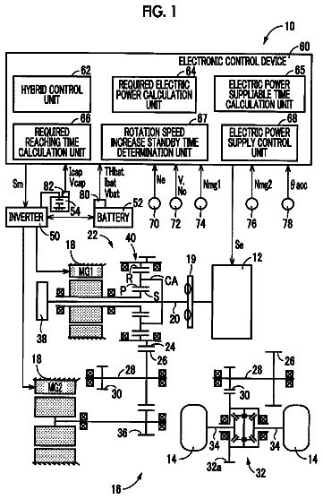
FIG. 1 is a view that shows the overall configuration of a hybrid vehicle according to an embodiment that is an example of the invention;
FIG. 2 is a block diagram that schematically shows power transmission paths of the hybrid vehicle shown in FIG. 1 ;
FIG. 3 is a block diagram that shows the configuration of a controller for the hybrid vehicle shown in FIG. 1 ;
FIG. 4 is a view that schematically shows the configuration of a hydraulic circuit mounted on the hybrid vehicle shown in FIG. 1 ;
FIG. 5 is a chart that shows each drive mode in the hybrid vehicle and a controlled status of a transmission unit (power transmission unit);
FIG. 6 is a nomograph in one-motor EV mode that is one of the drive modes shown in FIG. 5 ;
FIG. 7 is a nomograph in two-motor EV mode that is one of the drive modes shown in FIG. 5 ;
FIG. 8 is a first nomograph in series-parallel HV mode that is one of the drive modes shown in FIG. 5 ;
FIG. 9 is a nomograph in series HV mode that is one of the drive modes shown in FIG. 5 ;
FIG. 10 is a time chart that shows changes in the states of the hybrid vehicle at the time of switching from series-parallel mode to series mode among the drive modes shown in FIG. 5 ;
FIG. 11 is a first nomograph that shows an example of changes in the statuses of rotating elements at the time of switching from series parallel mode to series mode among the drive modes shown in FIG. 5 ;
FIG. 12 is a second nomograph that shows an example of changes in the statuses of the rotating elements at the time of switching from series-parallel mode to series mode among the drive modes shown in FIG. 5 ; and
FIG. 13 is a second nomograph in series-parallel HV mode that is one of the drive modes shown in FIG. 5 .
Hereinafter, an embodiment of the invention will be described with reference to the accompanying drawings. Like reference numerals denote the same or corresponding portions in the following embodiment, and the description thereof will not be repeated.
Initially, the overall configuration of a hybrid vehicle will be described. FIG. 1 is a view that shows the overall configuration of a hybrid vehicle (which may be simply referred to as vehicle) 1 according to the embodiment that is an example of the invention. The hybrid vehicle 1 includes an engine 10 , a drive system 2 , drive wheels 90 and a controller 100 . The drive system 2 includes a first motor generator (hereinafter, referred to as first MG) 20 that is a first rotary electric machine, a second motor generator (hereinafter, referred to as second MG) 30 that is a second rotary electric machine, a transmission unit (power transmission unit) 40 , a differential unit 50 , a clutch CS, an input shaft 21 , a counter shaft 70 that is an output shaft of the drive system 2 , a differential gear set 80 and a hydraulic circuit 500 .
The vehicle 1 is a front-engine front-drive (FF) hybrid vehicle that travels by using the power of at least any one of the engine 10 , the first MG 20 and the second MG 30 . The vehicle 1 may be a plug-in hybrid vehicle of which a battery (see FIG. 2 ) 60 is rechargeable from an external power supply.
The engine 10 is, for example, an internal combustion engine, such as a gasoline engine and a diesel engine. Each of the first MG 20 and the second MG 30 is, for example, a permanent magnet synchronous motor that includes a rotor in which permanent magnets are embedded. The drive system 2 is a double-axis drive system in which the first MG 20 is provided along a first axis 12 coaxial with the crankshaft of the engine 10 and the second MG 30 is provided along a second axis 14 different from the first axis 12 . The first axis 12 and the second axis 14 are parallel to each other.
The transmission unit 40 , the differential unit 50 and the clutch CS are further provided along the first axis 12 . The transmission unit 40 , the differential unit 50 , the first MG 20 and the clutch CS are arranged from the side close to the engine 10 in the stated order.
The first MG 20 is provided so as to be able to receive power from the engine 10 . More specifically, the input shaft 21 of the drive system 2 is connected to the crankshaft of the engine 10 . The input shaft 21 extends along the first axis 12 in a direction away from the engine 10 . The input shaft 21 is connected to the clutch CS at its distal end extending from the engine 10 . A rotary shaft 22 of the first MG 20 extends in a cylindrical shape along the first axis 12 . The input shaft 21 passes through the inside of the rotary shaft 22 at a portion before the input shaft 21 is connected to the clutch CS. The input shaft 21 is connected to the rotary shaft 22 of the first MG 20 via the clutch CS.
The clutch CS is a hydraulic friction engagement element that is able to couple the input shaft 21 to the rotary shaft 22 of the first MG 20 . When the clutch CS is placed in an engaged state, the input shaft 21 and the rotary shaft 22 are coupled to each other, and the power of the engine 10 is allowed to be directly transmitted to the first MG 20 via the clutch CS. On the other hand, when the clutch CS is placed in a released state, coupling of the input shaft 21 to the rotary shaft 22 is released, and the power of the engine 10 is not allowed to be directly transmitted to the first MG 20 via the clutch CS.
The transmission unit 40 shifts power from the engine 10 and then outputs the power to the differential unit 50 . The transmission unit 40 includes a single-pinion-type planetary gear mechanism, a clutch C 1 and a brake B 1 . The single-pinion-type planetary gear mechanism includes a sun gear S 1 , pinions P 1 , a ring gear R 1 and a carrier CA 1 .
The sun gear S 1 is provided such that the rotation center of the sun gear S 1 coincides with the first axis 12 . The ring gear R 1 is provided coaxially with the sun gear S 1 on the radially outer side of the sun gear S 1 . The pinions P 1 are arranged between the sun gear S 1 and the ring gear R 1 , and are in mesh with the sun gear S 1 and the ring gear R 1 . The pinions P 1 are rotatably supported by the carrier CA 1 . The carrier CA 1 is connected to the input shaft 21 , and rotates integrally with the input shaft 21 . Each of the pinions P 1 is provided so as to be revolvable about the first axis 12 and rotatable around the central axis of the pinion P 1 .
As will be described later, the rotation speed of the sun gear S 1 , the rotation speed of the carrier CA 1 (that is, the rotation speed of the engine 10 ) and the rotation speed of the ring gear R 1 are in the relationship represented by points that are connected by a straight line in each of the nomographs (that is, the relationship that, when any two rotation speeds are determined, the remaining one rotation speed is also determined).
In the present embodiment, the carrier CA 1 is provided as an input element to which power is input from the engine 10 , and the ring gear R 1 is provided as an output element that outputs the power input to the carrier CA 1 . By the use of the planetary gear mechanism including the sun gear S 1 , the pinions P 1 , the ring gear R 1 and the carrier CA 1 , power input to the carrier CA 1 is shifted and output from the ring gear R 1 .
The clutch C 1 is a hydraulic friction engagement element that is able to couple the sun gear S 1 to the carrier CA 1 . When the clutch C 1 is placed in an engaged state, the sun gear S 1 and the carrier CA 1 rotate integrally with each other. When the clutch C 1 is placed in a released state, integral rotation of the sun gear S 1 and the carrier CA 1 is cancelled.
The brake B 1 is a hydraulic friction engagement element that is able to restrict (lock) the rotation of the sun gear S 1 . When the brake B 1 is placed in an engaged state, the sun gear S 1 is fixed to the case body of the drive system, and the rotation of the sun gear S 1 is restricted. When the brake B 1 is placed in a released state (disengaged state), the sun gear S 1 is separated from the case body of the drive system, and the rotation of the sun gear S 1 is allowed.
A speed ratio (the ratio of the rotation speed of the carrier CA 1 that is the input element to the rotation speed of the ring gear R 1 that is the output element, specifically, Rotation Speed of Carrier CA 1 /Rotation Speed of Ring Gear R 1 ) of the transmission unit 40 is changed in response to a combination of the engaged/released states of the clutch C 1 and brake B 1 . When the clutch C 1 is engaged and the brake B 1 is released, a low gear position Lo in which the speed ratio is 1.0 (directly coupled state) is established. When the clutch C 1 is released and the brake B 1 is engaged, a high gear position Hi in which the speed ratio is smaller than 1.0 (for example, 0.7, and a so-called over-drive state) is established. When the clutch C 1 is engaged and the brake B 1 is engaged, the rotation of the sun gear S 1 and the rotation of the carrier CA 1 are restricted, so the rotation of the ring gear R 1 is also restricted.
The transmission unit 40 is configured to be able to switch between a non-neutral state and a neutral state. In the non-neutral state, power is transmitted. In the neutral state, power is not transmitted. In the present embodiment, the above-described directly coupled state and over-drive state correspond to the non-neutral state. On the other hand, when both the clutch C 1 and the brake B 1 are released, the carrier CA 1 is allowed to coast about the first axis 12 . Thus, the neutral state in which power transmitted from the engine 10 to the carrier CA 1 is not transmitted from the carrier CA 1 to the ring gear R 1 is obtained.
The differential unit 50 includes a single-pinion-type planetary gear mechanism and a counter drive gear 51 . The single-pinion-type planetary gear mechanism includes a sun gear S 2 , pinions P 2 , a ring gear R 2 and a carrier CA 2 .
The sun gear S 2 is provided such that the rotation center of the sun gear S 2 coincides with the first axis 12 . The ring gear R 2 is provided coaxially with the sun gear S 2 on the radially outer side of the sun gear S 2 . The pinions P 2 are arranged between the sun gear S 2 and the ring gear R 2 , and are in mesh with the sun gear S 2 and the ring gear R 2 . The pinions P 2 are rotatably supported by the carrier CA 2 . The carrier CA 2 is connected to the ring gear R 1 of the transmission unit 40 , and rotates integrally with the ring gear R 1 . Each of the pinions P 2 is provided so as to be revolvable about the first axis 12 and rotatable around the central axis of the pinion P 2 .
The rotary shaft 22 of the first MG 20 is connected to the sun gear S 2 . The rotary shaft 22 of the first MG 20 rotates integrally with the sun gear S 2 . The counter drive gear 51 is connected to the ring gear R 2 . The counter drive gear 51 is an output gear of the differential unit 50 . The output gear rotates integrally with the ring gear R 2 .
As will be described later, the rotation speed of the sun gear S 2 (that is, the rotation speed of the first MG 20 ), the rotation speed of the carrier CA 2 and the rotation speed of the ring gear R 2 are in the relationship represented by points that are connected by a straight line in each of the nomographs (that is, the relationship that, when any two rotation speeds are determined, the remaining one rotation speed is also determined). Therefore, when the rotation speed of the carrier CA 2 is a predetermined value, it is possible to steplessly change the rotation speed of the ring gear R 2 by adjusting the rotation speed of the first MG 20 .
The counter shaft 70 extends parallel to the first axis 12 and the second axis 14 . The counter shaft 70 is arranged parallel to the rotary shaft 22 of the first MG 20 and a rotary shaft 31 of the second MG 30 . A driven gear 71 and a drive gear 72 are provided on the counter shaft 70 . The driven gear 71 is in mesh with the counter drive gear 51 of the differential unit 50 . That is, the power of the engine 10 and the power of the first MG 20 are transmitted to the counter shaft 70 via the counter drive gear 51 of the differential unit 50 .
The transmission unit 40 and the differential unit 50 are connected in series with each other in a power transmission path from the engine 10 to the counter shaft 70 . Therefore, power from the engine 10 is shifted in the transmission unit 40 and the differential unit 50 and then transmitted to the counter shaft 70 .
The driven gear 71 is in mesh with a reduction gear 32 connected to the rotary shaft 31 of the second MG 30 . That is, the power of the second MG 30 is transmitted to the counter shaft 70 via the reduction gear 32 .
The drive gear 72 is in mesh with a differential ring gear 81 of the differential gear set 80 . The differential gear set 80 is connected to the right and left drive wheels 90 via corresponding right and left drive shafts 82 . That is, the rotation of the counter shaft 70 is transmitted to the right and left drive shafts 82 via the differential gear set 80 .
With the above-described configuration in which the clutch CS is provided, the hybrid vehicle 1 is allowed to operate in a mode in which a series-parallel system is used (hereinafter, referred to as series-parallel mode) and is also allowed to operate in a mode in which a series system is used (hereinafter, referred to as series mode). In terms of this point, how power is transmitted from the engine in each mode will be described with reference to the schematic view shown in FIG. 2 .
FIG. 2 is a block diagram that schematically shows power transmission paths of components of the hybrid vehicle shown in FIG. 1 . The hybrid vehicle 1 includes the engine 10 , the first MG 20 , the second MG 30 , the transmission unit 40 , the differential unit 50 , the battery 60 and the clutch CS. The battery 60 supplies electric power to the first MG 20 or the second MG 30 during motoring of a corresponding one of the first MG 20 and the second MG 30 , and stores electric power generated by the first MG 20 or the second MG 30 during regeneration of a corresponding one of the first MG 20 and the second MG 30 .
The hybrid vehicle 1 includes two paths K 1 , K 2 as a path through which the power of the engine 10 is transmitted to the first MG 20 .
The path K 1 is a path through which the power of the engine 10 is transmitted to the first MG 20 via the transmission unit 40 and the differential unit 50 . When the transmission unit 40 is placed in a non-neutral state (any one of the clutch C 1 and the brake B 1 is placed in the engaged state, and the other one of the clutch C 1 and the brake B 1 is placed in the released state), the power of the engine 10 is transmitted to the first MG 20 through the path K 1 . On the other hand, when the transmission unit 40 is placed in a neutral state (both the clutch C 1 and the brake B 1 are placed in the released state), transmission of power through the path K 1 is interrupted.
The path K 2 is different from the path K 1 , and is a path through which the power of the engine 10 is directly transmitted to the first MG 20 without passing through the transmission unit 40 or the differential unit 50 . The clutch CS is provided in the path K 2 . When the clutch CS is placed in the engaged state, the power of the engine 10 is transmitted to the first MG 20 through the path K 2 . On the other hand, when the clutch CS is placed in the released state, transmission of power through the path K 2 is interrupted.
In HV mode in which the engine 10 is operated, when the power of the engine 10 is transmitted through the path K 1 and the path K 2 is interrupted (that is, the transmission unit 40 is placed in the non-neutral state and the clutch CS is placed in the released state), the hybrid vehicle 1 is operable in series-parallel mode.
On the other hand, in HV mode in which the engine 10 is operated, when the power of the engine 10 is transmitted through the path K 2 and the path K 1 is interrupted (that is, the transmission unit 40 is placed in the neutral state and the clutch CS is placed in the engaged state), the hybrid vehicle 1 is operable in series mode. At this time, in the differential unit 50 , the carrier CA 2 connected to the transmission unit 40 is freely rotatable (free), so the sun gear S 2 connected to the first MG 20 and the ring gear R 2 connected to the second MG 30 do not influence each other and are rotatable. Therefore, it is possible to independently perform the operation of generating electric power by rotating the first MG 20 with the use of the rotation of the engine 10 and the operation of rotating the drive wheels by driving the second MG 30 .
The transmission unit 40 does not always need to be able to change the speed ratio. As long as it is possible to interrupt transmission of power through the path K 1 , a mere clutch is applicable.
The configuration of the controller will be described below. FIG. 3 is a block diagram that shows the configuration of the controller 100 of the hybrid vehicle 1 shown in FIG. 1 . The controller 100 includes an HV ECU 150 , an MG ECU 160 and an engine ECU 170 . Each of the HV ECU 150 , the MG ECU 160 and the engine ECU 170 is an electronic control unit including a computer. The number of ECUs is not limited to three. An integrated single ECU may be provided as a whole, or two or four or more of divided ECUs may be provided.
The MG ECU 160 controls the first MG 20 and the second MG 30 . The MG ECU 160 , for example, controls the output torque of the first MG 20 by adjusting the value of current that is supplied to the first MG 20 . The MG ECU 160 controls the output torque of the second MG 30 by adjusting the value of current that is supplied to the second MG 30 .
The engine ECU 170 controls the engine 10 . The engine ECU 170 , for example, controls the opening degree of an electronic throttle valve of the engine 10 , controls ignition of the engine by outputting an ignition signal, or controls injection of fuel to the engine 10 . The engine ECU 170 controls the output torque of the engine 10 through opening degree control over the electronic throttle valve, injection control, ignition control, and the like.
The HV ECU 150 comprehensively controls the entire vehicle. A vehicle speed sensor, an accelerator operation amount sensor, an MG 1 rotation speed sensor, an MG 2 rotation speed sensor, an output shaft rotation speed sensor, a battery sensor, and the like, are connected to the HV ECU 150 . With these sensors, the HV ECU 150 acquires a vehicle speed, an accelerator operation amount, the rotation speed of the first MG 20 , the rotation speed of the second MG 30 , the rotation speed of the output shaft of a power transmission system, a battery state SOC, and the like.
The HV ECU 150 calculates a required driving force, a required power, a required torque, and the like, for the vehicle based on acquired information. The HV ECU 150 determines the output torque of the first MG 20 (hereinafter, also referred to as MG 1 torque), the output torque of the second MG 30 (hereinafter, also referred to as MG 2 torque) and the output torque of the engine 10 (hereinafter, also referred to as engine torque) based on the calculated required values. The HV ECU 150 outputs a command value of the MG 1 torque and a command value of the MG 2 torque to the MG ECU 160 . The HV ECU 150 outputs a command value of the engine torque to the engine ECU 170 .
The HV ECU 150 controls the clutches C 1 , CS and the brake B 1 based on the drive mode (described later), and the like. The HV ECU 150 outputs, to the hydraulic circuit 500 shown in FIG. 1 , a command value (PbC 1 ) of hydraulic pressure that is supplied to the clutch C 1 , a command value (PbCS) of hydraulic pressure that is supplied to the clutch CS and a command value (PbB 1 ) of hydraulic pressure that is supplied to the brake B 1 .
The HV ECU 150 outputs a control signal NM for controlling an electric oil pump 502 (see FIG. 4 (described later)) and a control signal S/C for controlling an electromagnetic switching valve 560 (see FIG. 4 (described later)) to the hydraulic circuit 500 shown in FIG. 1 .
Next, the configuration of the hydraulic circuit will be described. FIG. 4 is a view that schematically shows the configuration of the hydraulic circuit 500 mounted on the hybrid vehicle 1 . The hydraulic circuit 500 includes a mechanical oil pump (hereinafter, also referred to as MOP) 501 , the electric oil pump (hereinafter, also referred to as EOP) 502 , pressure regulating valves 510 , 520 , linear solenoid valves SL 1 , SL 2 , SL 3 , simultaneous supply prevention valves 530 , 540 , 550 , an electromagnetic change-over valve 560 , a check valve 570 , and oil passages LM, LE, L 1 , L 2 , L 3 , L 4 .
The MOP 501 is connected to the carrier CA 2 among the three rotating elements (sun gear S 2 , ring gear R 2 , carrier CA 2 ) that constitute the differential unit 50 . More specifically, as shown in FIG. 1 , the MOP 501 is connected to the carrier CA 2 via a plurality of gears 506 , 507 . The gear 506 is connected to the carrier CA 2 of the differential unit 50 , and rotates integrally with the carrier CA 2 around a first axis 12 . The gear 507 is provided on the radially outer side of the gear 506 , and is in mesh with the gear 506 . A rotary shaft 508 of the gear 507 is connected to a drive shaft of the MOP 501 arranged coaxially with the rotary shaft 508 . With the above configuration, rotation of the carrier CA 2 of the differential unit 50 is transmitted to the drive shaft of the MOP 501 through the gear 506 and the gear 507 .
The MOP 501 is operated by power that is transmitted from the carrier CA 2 of the differential unit 50 to generate hydraulic pressure. Therefore, when the carrier CA 2 is rotated, the MOP 501 is also operated; whereas, when the carrier CA 2 is stopped, the MOP 501 is also stopped. The MOP 501 outputs generated hydraulic pressure to the oil passage LM.
One of the most characteristic points of the hydraulic circuit 500 according to the present embodiment is that the MOP 501 is connected to not the carrier CA 1 of the transmission unit 40 but the carrier CA 2 of the differential unit 50 . Thus, it is possible to operate the MOP 501 even in a state where rotation of the carrier CA 1 of the transmission unit 40 is stopped as a result of a stop of the engine 10 . This point will be described in detail later.
The hydraulic pressure in the oil passage LM is regulated (reduced) to a predetermined pressure by the pressure regulating valve 510 . Hereinafter, the hydraulic pressure in the oil passage LM, regulated by the pressure regulating valve 510 , is also referred to as line pressure PL. The line pressure PL is supplied to each of the linear solenoid valves SL 1 , SL 2 , SL 3 .
The linear solenoid valve SL 1 generates hydraulic pressure for engaging the clutch C 1 (hereinafter, referred to as C 1 pressure) by regulating the line pressure PL in response to the hydraulic pressure command value PbC 1 from the controller 100 . The C 1 pressure is supplied to the clutch C 1 via the oil passage L 1 .
The linear solenoid valve SL 2 generates hydraulic pressure for engaging the brake B 1 (hereinafter, referred to as B 1 pressure) by regulating the line pressure PL in response to the hydraulic pressure command value PbB 1 from the controller 100 . The B 1 pressure is supplied to the brake B 1 via the oil passage L 2 .
The linear solenoid valve SL 3 generates hydraulic pressure for engaging the clutch CS (hereinafter, referred to as CS pressure) by regulating the line pressure PL in response to the hydraulic pressure command value PbCS from the controller 100 . The CS pressure is supplied to the clutch CS via the oil passage L 3 .
The simultaneous supply prevention valve 530 is provided in the oil passage L 1 , and is configured to prevent the clutch C 1 and at least one of the brake B 1 and the clutch CS from being simultaneously engaged. Specifically, the oil passages L 2 , L 3 are connected to the simultaneous supply prevention valve 530 . The simultaneous supply prevention valve 530 operates by using the B 1 pressure and the CS pressure through the oil passages L 2 , L 3 as signal pressures.
When both signal pressures that are the B 1 pressure and the CS pressure are not input to the simultaneous supply prevention valve 530 (that is, when both the brake B 1 and the clutch CS are released), the simultaneous supply prevention valve 530 is in a normal state in which the C 1 pressure is supplied to the clutch C 1 . FIG. 4 illustrates the case where the simultaneous supply prevention valve 530 is in the normal state.
On the other hand, when at least one of the signal pressures that are the B 1 pressure and the CS pressure is input to the simultaneous supply prevention valve 530 (that is, when at least one of the brake B 1 and the clutch CS is engaged), even when the clutch C 1 is engaged, the simultaneous supply prevention valve 530 switches into a drain state in which supply of the C 1 pressure to the clutch C 1 is cut off and the hydraulic pressure in the clutch C 1 is released to the outside. Thus, the clutch C 1 is released, so the clutch C 1 and at least one of the brake B 1 and the clutch CS are prevented from being simultaneously engaged.
Similarly, the simultaneous supply prevention valve 540 operates in response to the C 1 pressure and the CS pressure as signal pressures to prevent the brake B 1 and at least one of the clutch C 1 and the clutch CS from being simultaneously engaged. Specifically, when both the signal pressures that are the C 1 pressure and the CS pressure are not input to the simultaneous supply prevention valve 540 , the simultaneous supply prevention valve 540 is in a normal state in which the B 1 pressure is supplied to the brake B 1 . On the other hand, when at least one of the signal pressures that are the C 1 pressure and the CS pressure is input to the simultaneous supply prevention valve 540 , the simultaneous supply prevention valve 540 switches into a drain state in which supply of the B 1 pressure to the brake B 1 is cut off and the hydraulic pressure in the brake B 1 is released to the outside. FIG. 4 illustrates the case where the C 1 pressure is input to the simultaneous supply prevention valve 540 as the signal pressure and the simultaneous supply prevention valve 540 is in the drain state.
Similarly, the simultaneous supply prevention valve (hydraulic valve) 550 operates by using the C 1 pressure and the B 1 pressure as signal pressures to prevent the clutch CS and at least one of the clutch C 1 and the brake B 1 from being simultaneously engaged. Specifically, when both the signal pressures that are the C 1 pressure and the B 1 pressure are not input to the simultaneous supply prevention valve 550 , the simultaneous supply prevention valve 550 is in a normal state in which the CS pressure is supplied to the clutch CS. On the other hand, when at least one of the signal pressures that are the C 1 pressure and the B 1 pressure is input to the simultaneous supply prevention valve 550 , the simultaneous supply prevention valve 550 switches into a drain state in which supply of the CS pressure to the clutch CS is cut off and the hydraulic pressure in the clutch CS is released to the outside. FIG. 4 illustrates the case where the C 1 pressure is input to the simultaneous supply prevention valve 550 and the simultaneous supply prevention valve 550 is in the drain state.
The EOP 502 is driven by a motor 502 A to generate hydraulic pressure. The motor 502 A is controlled by the control signal NM from the controller 100 . Therefore, the EOP 502 is operable irrespective of whether the carrier CA 2 is rotating. The EOP 502 outputs generated hydraulic pressure to the oil passage LE.
The description continues in the full USPTO document.
About 7,449 words. The USPTO PDF has it with every drawing.
Fees are due 3.5, 7.5 and 11.5 years after grant. This patent expired on May 22, 2026, so the fee marked "not paid" was the one that went unpaid.
HYBRID VEHICLE
Filed Feb 2016 · published Jan 2018Hybrid vehicle
Filed Feb 2016 · granted May 2018Earlier publications, parents and continuations. None of them can still be enforced, or this patent would not be listed.
Prior art cited by the examiner or applicant. Useful when you check your own idea for novelty.
Everything on this page comes from the documents linked above.