Incorporation by reference
The disclosure of Japanese Patent Application No. 2016-062782 filed on Mar. 25, 2016 including the specification, drawings and abstract is incorporated herein by reference in its entirety.
Background
1. Technical field
The present disclosure relates to a control device for a hybrid vehicle provided with a motor for drive, a capacitor, a motor for electric power generation, and an internal combustion engine.
2. Description of related art
A hybrid vehicle provided with a motor for drive configured to generate power for traveling, a capacitor configured to supply stored electric power to the motor for drive, a motor for electric power generation configured to supply generated electric power to the motor for drive, and an internal combustion engine configured to output power causing the motor for electric power generation to generate electric power is well known. For example, an example of such a hybrid vehicle is a hybrid vehicle described in Japanese Patent Application Publication No. 2014-218202 (JP 2014-218202 A). JP 2014-218202 A discloses a hybrid vehicle which is provided with a battery as a main power storage unit and a capacitor as an auxiliary power storage unit capable of supplying electric power to a motor for traveling and allows electric power to be supplied from the capacitor to the motor for traveling in consideration of fuel efficiency.
Summary
On the other hand, in a drive power non-generation state of the internal combustion engine in which power generated (unless otherwise specified, torque or force has the same meaning) by the internal combustion engine does not directly contribute to vehicle traveling and electric power generated by the motor for electric power generation with power generated by the internal combustion engine is not supplied to the motor for drive, when accelerating with an output of the motor for drive, it is considered that the motor for drive is first driven with electric power supplied from the capacitor, and the motor for drive is then driven with the generated electric power of the motor for electric power generation with power of the internal combustion engine. In such a case, if rotation speed increase control for increasing the rotation speed of the internal combustion engine for electric power generation of the motor for electric power generation after electric power has not been supplied from the capacitor starts to supply the generated electric power of the motor for electric power generation to the motor for drive, compensation for electric power with electric power generation of the motor for electric power generation is delayed with respect to a decrease in electric power of the capacitor. For this reason, the output of the motor for drive temporarily decreases and the required drive power of the vehicle cannot be satisfied, whereby drivability may be degraded.
The present disclosure provides a control device for a hybrid vehicle capable of suppressing degradation of drivability when accelerating with an output of a motor for drive.
A control device for hybrid vehicle according to an aspect of the present disclosure is provided. The hybrid vehicle includes a motor for drive, a capacitor, a motor for electric power generation, and an internal combustion engine. The motor for drive is configured to generate power for traveling the vehicle. The capacitor is configured to supply stored electric power to the motor for drive. The motor for electric power generation is configured to supply generated electric power to the motor for drive. The internal combustion engine is configured to outputs power to cause the motor for electric power generation to generate electric power. The control device includes an electronic control unit. The electronic control unit is configured to: calculate required electric power required for the motor for electric power generation as electric power supplied to the motor for drive based on required drive power of the hybrid vehicle; calculate an electric power suppliable time of the capacitor; and determine a rotation speed increase standby time of the internal combustion engine such that the rotation speed increase standby time becomes shorter than a spare time. The electric power suppliable time is a time from a time of starting a requirement of the required electric power until a time when charging capacity of the capacitor decreases to target residual capacity. The rotation speed increase standby time is a time from the time of starting the requirement of the required electric power until a time of starting a rotation speed increase. The time of starting the rotation speed increase is a time when the internal combustion engine, which is in a drive power non-generation state at the time of starting the requirement of the required electric power, starts rotation speed increase control for increasing the rotation speed for electric power generation of the motor for electric power generation. The spare time is a time obtained by subtracting an electric power generation delay time from the electric power suppliable time. The electric power generation delay time is a time from the time of starting the rotation speed increase until a time of starting electric power generation of the motor for electric power generation.
According to the control device of this aspect, the rotation speed increase standby time is determined such that the rotation speed increase standby time from the time of starting the requirement of the required electric power until the time of starting a rotation speed increase becomes shorter than the spare time obtained by subtracting, from the electric power suppliable time for which the capacitor is able to supply electric power, the predetermined electric power generation delay time from the time of starting a rotation speed increase when the rotation speed increase control for the internal combustion engine starts until the time of starting electric power generation of the motor for electric power generation. For this reason, the motor for drive is started to be driven with electric power supplied from the capacitor, and then, when the electric power suppliable time has elapsed and the capacitor does not supply electric power, the motor for drive is driven with the generated electric power of the motor for electric power generation. Hence, it is possible to suppress degradation of drivability when accelerating with an output of the motor for drive. Furthermore, when the rotation speed increase control of the internal combustion engine is delayed with respect to the time of starting the requirement, whereby it is possible to improve fuel efficiency.
In the control device according to the above-described aspect, the electronic control unit may be configured to calculate a required reaching time. The required reaching time may be a time from the time of starting electric power generation until a time of reaching of the requirement when the generated electric power of the motor for electric power generation reaches the required electric power. The electronic control unit may be configured to determine the rotation speed increase standby time such that the rotation speed increase standby time is equal to or less than a spare time obtained by subtracting the electric power generation delay time and the required reaching time from the electric power suppliable time.
According to the control device of this aspect, the rotation speed increase standby time is determined such that the rotation speed increase standby time becomes equal to or less than the spare time obtained by subtracting, from the electric power suppliable time, the electric power generation delay time and the required reaching time until the generated electric power of the motor for electric power generation reaches the required electric power. For this reason, the motor for drive is started to be driven with electric power supplied from the capacitor, and then, when the electric power suppliable time has elapsed and the capacitor does not supply electric power, the required electric power is satisfied with the generated electric power of the motor for electric power generation. Hence, it is possible to further suppress degradation of drivability when accelerating with the output of the motor for drive. Furthermore, the rotation speed increase control of the internal combustion engine is delayed with respect to the time of starting the requirement, whereby it is possible to improve fuel efficiency.
In the control device according to the above-described aspect, the electric power suppliable time may include a time for which the capacitor is able to supply the required electric power.
According to the control device of this aspect, since the electric power suppliable time includes a time for which the capacitor is able to supply the required electric power, acceleration is appropriately performed with the output of the motor for drive.
In the control device according to the above-described aspect, the electronic control unit may be configured to gradually decrease electric power supplied from the capacitor from the required electric power toward zero in conformity with an increase of the generated electric power of the motor for electric power generation from the time of starting electric power generation.
According to the control device of this aspect, electric power supplied from the capacitor gradually decreases from the required electric power toward zero in conformity with the increase of the generated electric power of the motor for electric power generation from the time of starting electric power generation. After electric power supplied from the capacitor decreases, the generated electric power of the motor for electric power generation instantly compensates for electric power. Hence, it is possible to further suppress degradation of drivability when accelerating with the output of the motor for drive. Furthermore, electric power supplied to the motor for drive is smoothly switched from electric power supplied from the capacitor to the generated electric power of the motor for electric power generation, and smooth acceleration is obtained.
In the control device according to the above-described aspect, the electric power suppliable time may include a time for which the capacitor is able to supply the required electric power and a time for which electric power supplied from the capacitor gradually decreases from the required electric power toward zero.
According to the control device of this aspect, the electric power suppliable time includes the time for which the capacitor is able to supply the required electric power and the time for which electric power supplied from the capacitor gradually decreases from the required electric power toward zero. For this reason, acceleration is appropriately performed with the output of the motor for drive, and electric power supplied to the motor for drive is smoothly switched from electric power supplied from the capacitor to the generated electric power of the motor for electric power generation. Furthermore, since the electric power suppliable time is further extended, the rotation speed increase standby time is extended, whereby it is possible to further improve fuel efficiency.
In the control device according to the above-described aspect, the electronic control unit may be configured to make the rotation speed increase standby time zero in a case where electric power to be output from the capacitor is less than the required electric power. The electronic control unit may be configured to calculate a required reaching time from the time of starting electric power generation until the time of reaching of the requirement when the generated electric power of the motor for electric power generation reaches the required electric power. The electronic control unit may be configured to gradually decrease electric power supplied from the capacitor toward zero from the time of starting the requirement such that the electric power suppliable time becomes equal to or greater than a total time of the electric power generation delay time and the required reaching time.
According to the control device of this aspect, the rotation speed increase standby time becomes zero in a case where electric power to be output from the capacitor is less than the required electric power, and electric power supplied from the capacitor gradually decreases toward zero from the time of starting the requirement such that the electric power suppliable time becomes equal to or greater than the total time of the electric power generation delay time and the required reaching time. Even in a case where electric power to be output from the capacitor is less than the required electric power, it is possible to compensate for a shortage of the generated electric power of the motor for electric power generation from the time of starting the requirement until the time of reaching of the requirement using electric power of the capacitor, and to suppress degradation of drivability. That is, in a case where electric power to be output from the capacitor is less than the required electric power, an aspect in which electric power of the capacitor compensates for a delay of the supply of generated electric power of the motor for electric power generation is employed, instead of employing an aspect in which electric power is not supplied from the capacitor. For this reason, it is possible to suppress degradation of drivability.
In the control device according to the above-described aspect, the hybrid vehicle may include a battery which is able to supply stored electric power to the motor for drive. The capacitor may be configured to supply electric power to the motor for drive in addition to electric power supplied from the battery. The electronic control unit may be configured to calculate, as the required electric power, a shortage of electric power with electric power supplied from the battery with respect to electric power required for an output of the motor for drive implementing the required drive power of the hybrid vehicle.
According to the control device of this aspect, a shortage of electric power with electric power supplied from the battery is supplied with the generated electric power of the motor for electric power generation. When the supply of generated electric power of the motor for electric power generation is started, after electric power of the capacitor is supplied, the motor for drive is driven with the generated electric power of the motor for electric power generation. Therefore, it is possible to suppress degradation of drivability when accelerating with the output of the motor for drive.
Brief description of the drawings
Features, advantages, and technical and industrial significance of exemplary embodiments of the present disclosure will be described below with reference to the accompanying drawings, in which like numerals denote like elements, and wherein:
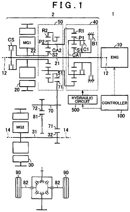
FIG. 1 is a diagram illustrating the schematic configuration of a vehicle to which the present disclosure is applied, and is a diagram illustrating a main part of a control system and a control function for various kinds of control in the vehicle;
FIG. 2 is a collinear diagram capable of relatively representing a rotation speed of each rotating element in a planetary gear mechanism, a solid line indicates an example of a traveling state in an HV traveling mode, and a broken line indicates an example of a traveling state in an EV traveling mode;
FIG. 3 is a diagram illustrating the relationship between capacitor output electric power and capacitor residual capacity;
FIG. 4 is a flowchart illustrating a main part of control operation of an electronic control device, that is, control operation for suppressing degradation of drivability when accelerating with an output of a second electric motor;
FIG. 5 is a time chart in a case where the control operation shown in the flowchart of FIG. 4 is executed in a case where an engine is in an operation stop state, and shows an example of a case where shortage MG2 power is covered with MG2 power for capacitor output electric power;
FIG. 6 is a time chart in a case where the control operation shown in the flowchart of FIG. 4 is executed in a case where the engine is in an idling state, and shows an example of a case where shortage MG2 power is covered with MG2 power for capacitor output electric power;
FIG. 7 is a time chart in a case where the control operation shown in the flowchart of FIG. 4 is executed in a case where the engine is in a motoring state, and shows an example of a case where shortage MG2 power is covered with MG2 power for capacitor output electric power;
FIG. 8 is a time chart in a case where the control operation shown in the flowchart of FIG. 4 is executed in a case where the engine is in the operation stop state, and shows an example of a case where shortage MG2 power is not covered with MG2 power for capacitor output electric power;
FIG. 9 is a flowchart illustrating a comparative example of this example shown in the flowchart of FIG. 4 ;
FIG. 10 is a time chart in a case where the control operation shown in the flowchart of FIG. 9 is executed in a case where the engine is in the operation stop state, and shows an example of a case where shortage MG2 power is covered with the MG2 power for capacitor output electric power; and
FIG. 11 is a time chart in a case where the control operation shown in the flowchart of FIG. 9 is executed in a case where the engine is in the operation stop state, and shows an example of a case where shortage MG2 power is not covered with MG2 power for capacitor output electric power.
Detailed description of embodiments
Hereinafter, an example of the present disclosure will be described in detail referring to the drawings.
FIG. 1 is a diagram illustrating the schematic configuration of a hybrid vehicle 10 (hereinafter, referred to as a vehicle 10 ) to which the present disclosure is applied, and is a diagram illustrating a main part of a control system for various kinds of control in the vehicle 10 . In FIG. 1 , the vehicle 10 is a hybrid vehicle which is provided with an engine 12 as an internal combustion engine which is a drive power source for traveling generating power for traveling, and a second electric motor MG2 as a motor for drive. Furthermore, the vehicle 10 is provided with drive wheels 14 , a power transmission device 16 provided in a power transmission path between the engine 12 and the drive wheels 14 , and a first electric motor MG1.
The power transmission device 16 is housed in an unrotatable case 18 which is a non-rotating member attached to a vehicle body. The power transmission device 16 is provided with a damper 19 coupled to the engine 12 , an input shaft 20 coupled to the damper 19 , a gear shift unit 22 coupled to the input shaft 20 , a driven gear 26 which meshes with a drive gear 24 as an output rotating member of the gear shift unit 22 , a final gear 30 which is provided to be relatively unrotatable in a driven shaft 28 fixing the driven gear 26 to be relatively unrotatable and has a diameter smaller than the driven gear 26 , a differential gear 32 which meshes with the final gear 30 through a differential ring gear 32 a , an axle 34 coupled to the differential gear 32 , a reduction gear 36 which meshes with the driven gear 26 , is coupled to the second electric motor MG2, and has a diameter smaller than the driven gear 26 , a mechanical oil pump 38 (hereinafter, referred to as a MOP 38 ) which is driven through the input shaft 20 when the input shaft 20 is rotationally driven by the engine 12 , and the like. In the power transmission device 16 configured as above, power (unless otherwise specified, torque or force has the same meaning) output from the engine 12 or power output from the second electric motor MG2 is transmitted to the driven gear 26 , and is transmitted from the driven gear 26 to the drive wheels 14 through the final gear 30 , the differential gear 32 , the axle 34 , and the like in order.
The gear shift unit 22 has a planetary gear mechanism 40 as a power distribution mechanism which distributes power transmitted from the engine 12 through the input shaft 20 to the first electric motor MG1 and the drive gear 24 . The planetary gear mechanism 40 is a known single-pinion type planetary gear device provided with a sun gear S, a pinion gear P, a carrier CA which supports the pinion gear P to be rotatable and revolvable, and a ring gear R which meshes with the sun gear S through the pinion gear P, and functions as a different mechanism which generates a differential action. In the planetary gear mechanism 40 , the sun gear S is coupled to the first electric motor MG1, the carrier CA is coupled to the engine 12 through the input shaft 20 , and the ring gear R is formed in the inner circumferential surface of the drive gear 24 . In the planetary gear mechanism 40 configured as above, the first electric motor MG1 generates electric power with power of the engine 12 distributed to the first electric motor MG1, and the generated electric power is stored or the second electric motor MG2 is driven with the electric power. With this, the gear shift unit 22 functions an electric differential unit (electric continuously variable transmission) in which a gear ratio is controlled by controlling the operation state of the first electric motor MG1 In this way, the first electric motor MG1 is a motor for electric power generation which is able to supply the generated electric power to the second electric motor MG2, and the engine 12 is an internal combustion engine which outputs power to cause the first electric motor MG1 to generate electric power.
The MOP 38 is rotationally driven by the engine 12 and supplies (ejects) oil used for lubricating or cooling the respective units of the power transmission device 16 , such as the differential gear 32 , the reduction gear 36 , the planetary gear mechanism 40 , and a ball bearing.
The vehicle 10 is further provided with an inverter 50 which controls transmission and reception of electric power related to operation of each of the electric motors MG1, MG2 such that output torque (powering torque or regenerative torque) required for each of the first electric motor MG1 and the second electric motor MG2 is obtained, a battery 52 as a power storage device which performs transmission and reception of electric power with respect to each of the first electric motor MG1 and the second electric motor MG2, and a capacitor 54 as a capacitor which performs transmission and reception of electric power with respect to each of the first electric motor MG1 and the second electric motor MG2. Each of the battery 52 and the capacitor 54 is a power storage device which is able to store electric power generated by each of the first electric motor MG1 and the second electric motor MG2 and to supply the stored electric power to each of the first electric motor MG1 and the second electric motor MG2. For example, a maximum value of charging capacity (that is, battery residual capacity) SOCbat of the battery 52 is greater than a maximum value of a charging capacity (that is, capacitor residual capacity) SOCcap of the capacitor 54 , and a maximum value of electric power (that is, capacitor output electric power) Pcap output (supplied) from the capacitor 54 is greater than a maximum value of electric power (that is, battery output electric power) Pbat output (supplied) from the battery 52 . Accordingly, the battery 52 is a main power storage device Which continuously outputs the electric power Pbat. Furthermore, the capacitor 54 is a sub-power storage device which temporarily outputs a part or the whole of a shortage of electric power with the battery output electric power Pbat, and is an auxiliary power storage device which supplies the electric power Pcap to the second electric motor MG2 in addition to the battery output electric power Pbat.
Both of the first electric motor MG1 and the second electric motor MG2 are motor generators which have a function as a motor (motor) operable to generate mechanical power from electric power and a function as a power generator (generator) operable to generate electric power from mechanical power, and are selectively operated as a motor or a power generator. Each of the electric motors MG1, MG2 is connected to the battery 52 (and the capacitor 54 ) through the inverter 50 , and the inverter 50 is controlled by an electronic control unit 60 described below, whereby MG1 torque Tmg1 which is output torque of the first electric motor MG1 and MG2 torque Tmg2 which is output torque of the second electric motor MG2 are controlled.
The vehicle 10 is further provided with an electronic control unit 60 including a control device of the vehicle 10 related to control of the engine 12 , control of the electric motors MG1, MG2, or the like. Hence, FIG. 1 is a diagram showing an input/output system of the electronic control unit 60 , and is a functional block diagram illustrating a main part of a control function of the electronic control unit 60 . The electronic control unit 60 includes a so-called microcomputer provided with, for example, a CPU, a RAM, a ROM, an input/output interface, and the like, and the CPU performs signal processing according to a program stored in advance in the ROM while using a temporary storage function of the RAM vehicle 10 , thereby executing various kinds of control of the vehicle 10 . For example, the electronic control unit 60 executes vehicle control, such as hybrid drive control relating to the engine 12 , the first electric motor MG1, the second electric motor MG2, or the like, and includes each computer for engine control, electric motor control, or the like as necessary.
To the electronic control unit 60 , various actual values (for example, an engine rotation speed Ne, an output rotation speed No which is the rotation speed of the drive gear 24 corresponding to a vehicle speed V, a MG1 rotation speed Nmg1 which is the rotation speed of the first electric motor MG1, a MG2 rotation speed Nmg2 which is the rotation speed of the second electric motor MG2, an accelerator pedal angle θacc, a battery temperature THbat, a battery charging/discharging current Ibat, a battery voltage Vbat of the battery 52 , a capacitor charging/discharging current Icap or a capacitor voltage Vcap of the capacitor 54 , and the like) based on detection signals detected by various sensors (for example, an engine rotation speed sensor 70 , an output rotation speed sensor 72 , a MG1 rotation speed sensor 74 , such as a resolver, a MG2 rotation speed sensor 76 , such as a resolver, an accelerator pedal angle sensor 78 , a battery sensor 80 , a capacitor sensor 82 , and the like) in the vehicle 10 are supplied. From the electronic control unit 60 , various command signals (for example, an engine control command signal Se for controlling the engine 12 , an electric motor control command signal Sm for operating the inverter 50 controlling each of the electric motors MG1, MG2, and the like) are output to the respective devices (for example, an engine control device such as a throttle actuator or a fuel injection device, the inverter 50 , and the like) in the vehicle 10 . The electronic control unit 60 calculates the battery residual capacity SOCbat based on the battery charging/discharging current Ibat, the battery voltage Vbat, and the like and calculates the capacitor residual capacity SOCcap based on the capacitor charging/discharging current Icap, the capacitor voltage Vcap, and the like, for example,.
The electronic control unit 60 is provided with hybrid control means, that is, a hybrid control unit 62 in order to implement the control function for various kinds of control in the vehicle 10 .
The hybrid control unit 62 controls opening and closing of an electronic throttle valve, controls a fuel injection amount or an injection timing, and outputs the engine control command signal Se for controlling an ignition timing to execute output control of the engine 12 such that a target value of engine torque Te is obtained. Furthermore, the hybrid control unit 62 outputs the electric motor control command signal Sm for controlling the operation of the first electric motor MG1 or the second electric motor MG2 to the inverter 50 to execute output control of the first electric motor MG1 or the second electric motor MG2 such that a target value of the MG1 torque Tmg1 or the MG2 torque Tmg2 is obtained.
Specifically, the hybrid control unit 62 applies the accelerator pedal angle θacc or the vehicle speed V to a relationship (required drive power map) calculated in advance (determined in advance) by an experiment or in design to calculate required drive power Fddem in the drive wheels 14 as a required drive amount of a driver to the vehicle 10 . Then, the hybrid control unit 62 implements the required drive power Fddem with an output (engine power Pe [W] and/or MG2 power Pmg2[W]) from at least one of the engine 12 or the second electric motor MG2 such that driving with low fuel consumption and a small amount of exhaust gas is performed in consideration of a transmission loss, an accessory load, a required charging value (required charging power), and the like. As the required drive amount, in addition to the required drive power Fddem [N], required drive power [W] in the drive wheels 14 , require drive torque [Nm] in the drive wheels 14 , or the like may be used. Furthermore, as the required drive amount, the accelerator pedal angle θacc [%], a throttle valve opening [%], an intake air amount [g/sec], or the like may be simply used.
The hybrid control unit 62 selectively establishes, as a traveling mode, an EV traveling mode or an HV traveling mode described below according to a traveling state. For example, the hybrid control unit 62 establishes the EV traveling mode in a case where the required drive power Fddem is in a motor traveling region smaller than a threshold determined in advance, and establishes the HV traveling mode in a case where the required drive power Fddem is in an engine traveling region equal to or greater than the threshold determined in advance. Furthermore, the hybrid control unit 62 establishes the HV traveling mode in a case where the battery residual capacity SOCbat becomes less than a threshold determined in advance even when the required drive power Fddem is in the motor traveling region.
When the EV traveling mode is established, the hybrid control unit 62 stops the operation of the engine 12 and enables motor traveling (EV traveling) with only the second electric motor MG2 as a drive power source for traveling.
When the HV traveling mode is established, the hybrid control unit 62 bears reaction force to the power of the engine 12 with electric power generation of the first electric motor MG1 to transmit directly transmitted engine torque to the drive gear 24 and drives the second electric motor MG2 with the generated electric power of the first electric motor MG1 to transmit torque to the drive wheels 14 , thereby enabling engine traveling with at least the engine 12 as a drive power source for traveling. That is, in a case where the HV traveling mode is established, the hybrid control unit 62 controls the operation state of the first electric motor MG1 to enable engine traveling in which traveling is performed by transmitting the power of the engine 12 to the drive wheels 14 . In the HV traveling mode, traveling may be performed by further adding drive torque of the second electric motor MG2 using power from the battery 52 .
FIG. 2 is a collinear diagram capable of relatively representing the rotation speeds of three rotating elements RE 1 , RE 2 , RE 3 in the planetary gear mechanism 40 . The collinear diagram has vertical lines Y 1 to Y 3 in order from the left toward the paper, the vertical line Y 1 indicates the rotation speed of the sun gear S which is a second rotating element RE 2 coupled to the first electric motor MG1, the vertical line Y 2 indicates the rotation speed of the carrier CA which is a first rotating element RE 1 coupled to the engine (ENG) 12 , and the vertical line Y 3 indicates the rotation speed of the ring gear R which is a third rotating element RE 3 coupled to the second electric motor MG2 through the driven gear 26 , the reduction gear 36 , and the like. A solid line of FIG. 2 indicates an example of a relative speed of each rotating element in a traveling state in the HV traveling mode, and a broken line of FIG. 2 indicates an example of a relative speed of each rotating element in a traveling state in the EV traveling mode.
The operation of the vehicle 10 in the HV traveling mode will be described using the solid line of FIG. 2 . The MG1 torque Tmg1 is input to the sun gear S with respect to the engine torque Te which is input to the carrier CA. At this time, for example, it is possible to perform control for setting an operation point of the engine 12 represented by the engine rotation speed Ne and the engine torque Te as an operation point with the best fuel efficiency through powering control or reaction force control of the first electric motor MG1. This type of hybrid form is called a mechanical distribution type or a split type.
The operation of the vehicle 10 in the EV traveling mode will be described using the broken line of FIG. 2 . The engine 12 is not driven (that is, the engine 12 is in an operation stop state), the first electric motor MG1 is a no-load state (free), and the engine rotation speed Ne becomes zero. In this state, the powering torque of the second electric motor MG2 is transmitted to the drive wheels 14 as drive power in a vehicle forward movement direction. Although a case where the engine 12 is brought into the operation stop state in the EV traveling mode has been illustrated, the engine 12 may be in a drive power non-generation state in the EV traveling mode. The drive power non-generation state of the engine 12 is a state in which power generated by the engine 12 does not directly contribute to traveling (drive power) of the vehicle 10 and a state in which electric power generated by the first electric motor MG1 with power generated by the engine 12 is not supplied to the second electric motor MG2. As the drive power non-generation state of the engine 12 , for example, a case where the engine 12 is in the operation stop state, a case where the engine 12 is in an idling state, or a case where the engine 12 is in a motoring state of being rotationally driven by the first electric motor MG1 is exemplified. The idling state of the engine 12 is a state in which the engine 12 outputs power for driving vehicle accessories and is driven at a low engine rotation speed Ne, such as an idling rotation speed, in order to output power required for an autonomous operation of the engine 12 , in which power generated by the engine 12 does not directly contributes to vehicle traveling, and electric power generated by the first electric motor MG1 with power generated by the engine 12 is not supplied to the second electric motor MG2, for example. The motoring state of the engine 12 is a state in which the output shaft of the engine 12 is rotationally driven at a low engine rotation speed Ne by the first electric motor MG1, the engine 12 does not generate power contributing to vehicle traveling, and electric power generation of the first electric motor MG1 is not performed since the first electric motor MG1 is powering (outputs positive torque), for example,
A case where there is a shortage of electric power required for the MG2 power Pmg2, which is the output of the second electric motor MG2 implementing the required drive power Fddem of the vehicle 10 , with the battery output electric power Pbat in the EV traveling mode since an upper limit of the output of the battery output electric power Pbat becomes small due to any reason, such as a low battery temperature THbat is considered. In such a case, it is considered that the second electric motor MG2 is driven with the capacitor output electric power Pcap, and then, the second electric motor MG2 is driven with the generated electric power Pmg1 of the first electric motor MG1 with the power of the engine 12 . At this time, in a case where the whole of a shortage of electric power with the battery output electric power Pbat is not covered with the capacitor output electric power Pcap, it is considered that the capacitor output electric power Pcap is not used, and the second electric motor MG2 is driven with the generated electric power Pmg1 of the first electric motor MG1 with the power of the engine 12 from the beginning. On the other hand, since the engine 12 is in the drive power non-generation state in the EV traveling mode, for electric power generation of the first electric motor MG1, it is necessary to increase the engine rotation speed Ne. For example, for electric power generation of the first electric motor MG1 in a case where the operation of the engine 12 is stopped, it is necessary to start the engine 12 . After the increase of the engine rotation speed Ne starts (for example, after the engine 12 starts in a case where the operation of the engine 12 is stopped), the generated electric power Pmg1 of the first electric motor MG1 is not supplied until the engine rotation speed Ne increases and becomes the engine rotation speed Ne at which electric power generation can be performed in the first electric motor MG1, and it takes a lot of time until the generated electric power Pmg1 becomes a shortage of electric power with the battery output electric power Pbat. For this reason, according to the timing at which rotation speed increase control for increasing the engine rotation speed Ne for electric power generation of the first electric motor MG1 is executed after the second electric motor MG2 is driven with the capacitor output electric power Pcap (for example, the engine 12 starts in a case where the operation of the engine 12 is stopped), compensation of the generated electric power Pmg1 is delayed with respect to a decrease in the capacitor output electric power Pcap, the MG2 power Pmg2 temporarily decreases, and the required drive power Fddem of the vehicle 10 cannot be satisfied, whereby drivability may be degraded. In a case where the capacitor output electric power Pcap is not used and the rotation speed increase control of the engine 12 is executed from the beginning (for example, the engine 12 starts in a case where the operation of the engine 12 is stopped), a rise in the MG2 power Pmg2 may stagnate at the MG2 power Pmg2 for the battery output electric power Pbat until the generated electric power Pmg1 is generated. The rotation speed increase control of the engine 12 for electric power generation of the first electric motor MG1 is control for increasing the engine rotation speed Ne in order to cover electric power required for the second electric motor MG2 to implement the required drive power Fddem of the vehicle 10 with the generated electric power Pmg1 of the first electric motor MG1.
Accordingly, the electronic control unit 60 controls switching between the capacitor output electric power Pcap and the generated electric power Pmg1 of the first electric motor MG1 with the power of the engine 12 according to the capacitor residual capacity SOCcap, thereby implementing smooth acceleration and practical fuel efficiency improvement.
The description continues in the full USPTO document.
 Lapsed, fee not paid6 drawings