Field
Embodiments of the present invention relate to a battery and a seal unit.
Background
Generally, a battery such as a primary battery and a secondary battery includes an electrode body including a positive electrode and a negative electrode, and an container member housing the electrode body.
Presently, a metal can has been put to practical use as the container member housing the positive electrode and negative electrode or the like of the battery. In a sealed battery using the metal can, the opening of the metal can is sealed with a lid. A through hole for fixing an output terminal is present in the lid. The output terminal is fixed in a state where it passes through the lid up and down via a gasket made of resin or rubber. The gasket serves as an insulator avoiding direct contact between the output terminal and the lid. In this case, the output terminal includes a head part exposed from the external surface of the gasket and a shaft fitted into the gasket. The shaft of the output terminal is subjected to a pressure by a press including a punch which apples a pressure to the shaft perpendicularly to a direction in which the shaft extends to caulk the output terminal. The caulking expands the shaft and presses the cylindrical shaft of the gasket against the side wall of the through hole of the lid, to fix the output terminal and the gasket.
The lid of the metal can may have a structure for fixing the output terminal in order to exhibit high sealing performance of the battery together with the gasket. Such a structure can be formed by, for example, deep drawing or the like.
On the other hand, a laminate including a metal or metal layer and resin layer and having a small thickness can be used as the other container member housing the electrodes of the battery. Such a container member is generally more lightweight than the metal can. Therefore, the use of such a container member can provide a battery having a higher energy density per weight.
Brief description of drawings
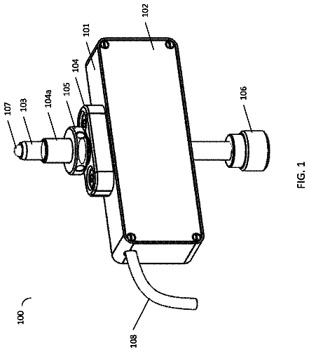
FIG. 1 is a schematic perspective view of a battery as a first example according to a first embodiment.
FIG. 2 is a schematic exploded perspective view of an end part including a positive electrode terminal of the battery as the first example.
FIG. 3 is a schematic sectional view taken along line segment III-III′ of the battery shown in FIG. 1 .
FIG. 4 is an enlarged view of a portion IV of FIG. 3 .
FIG. 5 is a schematic sectional view showing a state before the positive electrode terminal is incorporated in an example of a production process of the battery as the first example.
FIG. 6 is a schematic perspective view of a battery as a second example according to the first embodiment.
FIG. 7 is a schematic exploded perspective view of an end part including a positive electrode terminal of the battery as the second example.
FIG. 8 is a schematic sectional view taken along line segment VIII-VIII′ of the battery shown in FIG. 6 .
FIG. 9 is a schematic sectional view of a variant example of the battery as the second example.
FIG. 10 is a schematic sectional view of an end part including a positive electrode terminal of a battery as a third example according to the first embodiment.
FIG. 11 is a schematic sectional view of an end part including a positive electrode terminal of a battery as a fourth example according to the first embodiment.
FIG. 12 is an enlarged view of a portion XII of FIG. 11 .
FIG. 13 is a schematic perspective view of a seal unit as a first example according to a second embodiment.
FIG. 14 is a schematic exploded perspective view of the seal unit of FIG. 13 .
FIG. 15 is a schematic sectional view taken along line III-III′ of the seal member shown in FIG. 14 .
FIG. 16 is a schematic sectional view taken along line IV-IV′ of the seal unit shown in FIG. 13 .
FIG. 17 is an enlarged sectional view of a portion v of FIG. 16 .
FIG. 18 is a schematic sectional view showing a state before a terminal is incorporated in an example of a production process of the seal unit as the first example.
FIG. 19 is a schematic perspective view of a seal unit as a second example according to the second embodiment.
FIG. 20 is a schematic exploded perspective view of the seal unit shown in FIG. 19 .
FIG. 21 is a schematic sectional view taken along line IX-IX′ of the seal unit shown in FIG. 19 .
FIG. 22 shows an example of a production process of a terminal-connecting part of the seal member which can be included in the seal unit according to the second embodiment.
FIG. 23 is a schematic exploded perspective view of a battery as an example according to a third embodiment.
Detailed description
In general, according to an embodiment, a battery is provided. The battery includes an electrode body, a lead electrically connected to the electrode body, a container member housing the electrode body and the lead, a gasket, an external terminal, and a restraining member. The container member includes a terminal-connecting part having a thickness of 0.3 mm or less. The terminal-connecting part includes a through hole and a rising part extending toward an inside of the container member from an edge part of the through hole. The rising part includes a diameter-reduction part having a diameter reduced along a direction toward the inside of the container member from the edge part of the through hole. The gasket includes a hollow shaft. The hollow shaft of the gasket is inserted into the rising part. The external terminal includes a first end part and a second end part, and includes a terminal shaft extending to an axial direction toward the second end part from the first end part. The terminal shaft passes through the shaft of the gasket, and is electrically connected to the lead. The terminal shaft includes a diameter-reduction part having a diameter reduced along the axial direction. The restraining member restrains at least a part of the diameter-reduction part of the terminal shaft via the diameter-reduction part of the rising part and the shaft of the gasket. The inclination angle of the diameter-reduction part of the rising part to the axial direction of the terminal shaft is larger than the inclination angle of the diameter-reduction part of the terminal shaft to the axial direction of the terminal axial part.
Hereinafter, the embodiments will be described with reference to the drawings. The same reference numerals denote common portions throughout the embodiments and overlapping descriptions are avoided. Each of these drawings is a typical view for descriptions and promotion of the understanding of the embodiment. Though there are parts different from an actual device in shape, dimension and ratio, these structural designs may be properly changed taking the following descriptions and known technologies into consideration. First Embodiment
According to a first embodiment, a battery is provided. The battery includes an electrode body, a lead electrically connected to the electrode body, a container member housing the electrode body and the lead, a gasket, an external terminal, and a restraining member. The container member includes a terminal-connecting part having a thickness of 0.3 mm or less. The terminal-connecting part includes a through hole and a rising part extending toward an inside of the container member from an edge part of the through hole. The rising part includes a diameter reduction part having a diameter reduced along a direction toward the inside of the container member from the edge part of the through hole. The gasket includes a hollow shaft. The hollow shaft of the gasket is inserted into the rising part. The external terminal includes a first end part and a second end part, and includes a terminal shaft extending to an axial direction toward the second end part from the first end part. The terminal shaft passes through the shaft of the gasket, and is electrically connected to the lead. The terminal shaft includes a diameter-reduction part having a diameter reduced along the axial direction. The restraining member restrains at least a part of the diameter-reduction part of the terminal shaft via the diameter-reduction part of the rising part and the shaft of the gasket. The inclination angle of the diameter-reduction part of the rising part to the axial direction of the terminal shaft is larger than the inclination angle of the diameter-reduction part of the terminal shaft to the axial direction of the terminal shaft.
It may be difficult to subject a portion having a small thickness of, for example, 0.3 mm or less in a plate to deep drawing or the like because of the small thickness. Therefore, it may be difficult to provide the same terminal structure as that capable of being provided on a lid of a metal can by deep drawing on a terminal-connecting part having a small thickness.
As a result of intensive studies from such a background, the inventors could provide a terminal structure capable of exhibiting high sealing performance on a terminal-connecting part having a small thickness. That is, in the battery according to the first embodiment, the terminal-connecting part having a thickness of 0.3 mm or less can include the terminal structure capable of exhibiting high sealing performance. Hereinafter, regarding the battery according to the first embodiment, the reason why the terminal structure provided on the terminal-connecting part having a small thickness can exhibit high sealing performance will be described.
First, in the battery according to the first embodiment, a terminal-connecting part of a container member includes a through hole and a rising part extending toward an inside of the container member from an edge part of the through hole. The rising part includes a diameter-reduction part having a diameter reduced along a direction toward the inside of the container member from the edge part of the through hole. A hollow shaft of a gasket is inserted into the rising part. The terminal shaft of the external terminal passes through the shaft of the gasket. The terminal shaft of the external terminal includes a diameter-reduction part having a diameter reduced along the axial direction. The inclination angle of the rising part to the axial direction of the terminal shaft is larger than the inclination angle of the terminal shaft to the axial direction of the terminal shaft.
A portion sandwiched between the diameter-reduction part of the rising part and the diameter-reduction part of the terminal shaft which have such different angles of inclination in the shaft of the gasket is subjected to pressure from the diameter-reduction part of the terminal shaft and the diameter-reduction part of the rising part.
On the other hand, in the battery according to the first embodiment, the restraining member restrains at least a part of the diameter-reduction part of the terminal shaft via the diameter-reduction part of the rising part and the shaft of the gasket. Therefore, pressure applied to the gasket from the diameter-reduction part of the terminal shaft is transmitted to the diameter-reduction part of the rising part, and eventually the restraining member. The restraining member can transmit a counteraction against the pressure from the diameter-reduction part of the terminal shaft as a restraining force to the gasket through the diameter-reduction part of the rising part.
Thus, in the battery according to the first embodiment, the gasket can be subjected to the pressure from the diameter-reduction part of the terminal shaft, and the pressure and the restraining force from the diameter-reduction part of the rising part. Because of this, the battery according to the first embodiment can achieve high tightness of contact between the terminal axial part and the gasket and of contact between the rising part and the gasket, and as a result can exhibit high sealing performance.
Since a portion sandwiched between the diameter-reduction part of the rising part and the diameter-reduction part of the terminal shaft in the shaft of the gasket is subjected to the pressure from the diameter-reduction part of the rising part of the container member and the diameter-reduction part of the terminal shaft, as described above, the portion may be compressed. Thereby, the shaft of the gasket can include portions having different thicknesses. Since the diameters of the diameter-reduction part of the rising part and diameter-reduction part of the terminal shaft are reduced along a direction toward the inside of the container member, a portion which is farther from the edge part of the through hole of the container member among the portion sandwiched between the diameter-reduction part of the rising part and the diameter-reduction part of the terminal shaft in the shaft of the gasket may be subjected to larger pressure. Therefore, a portion having the maximum thickness of the shaft of the gasket, i.e., a portion subjected to less pressure and having a small compression ratio, a portion not subjected to pressure and not compressed, or a portion expanded by elastic deformation caused by the compression of a part of the shaft of the gasket may be disposed closer to the edge part of the through hole of the container member than a portion having the minimum thickness of the shaft of the gasket, i.e., a portion largely compressed by large pressure. That is, when the portion having the maximum thickness of the axial part of the gasket is defined as a first portion and the portion having the minimum thickness of the axial part of the gasket is defined as a second portion, the first portion may be disposed closer to the edge part of the through hole of the container member than the second portion.
The rising part of the container member included in the battery according to the first embodiment can be formed by burring. Generally, stress occurring in a workpiece in the burring can be made smaller than that in deep drawing. Therefore, in the battery according to the first embodiment, the rising part can be formed in the terminal-connecting part having a thickness of 0.3 mm or less by burring. That is, the first embodiment can provide the battery in which the terminal-connecting part having a small thickness can include the terminal structure capable of exhibiting high sealing performance.
The inclination angle of the rising part, the inclination angle of the terminal shaft, and the thickness of the shaft of the gasket in the battery can be measured in the following procedures, for example. First, a resin is injected into the battery, and the resin is cured. By cutting through a battery having the cured inner part, the cross-sectional surface of the battery can be obtained while the positions of the lead, the container member, the gasket, the external terminal, and the restraining member are maintained.
The inclination angle can be confirmed from cross-sectional surfaces obtained by cutting through the battery in an x direction, a y direction, and a direction of 45 degrees on the basis of the axial direction of the external terminal, for example. When the diameter-reduction part arrives at the tip of the rising part, regarding the inclination angle of the diameter-reduction part of the rising part, the inclination angle in the tip of the rising part is measured as the inclination angle of the diameter-reduction part of the rising part. On the other hand, when the diameter-reduction part does not arrive at the tip of the rising part, the inclination angle of a portion close to the tip of the rising part in the diameter-reduction part is measured as the inclination angle of the diameter-reduction part of the rising part. When the diameter-reduction part of the rising part arrives at the tip of the rising part, regarding the inclination angle of the diameter reduction part of the external terminal, the inclination angle of a portion sandwiching a part of the gasket together with the tip of the rising part is measured as the inclination angle of the diameter-reduction part of the external terminal. On the other hand, when the diameter-reduction part does not arrive at the tip of the rising part, the inclination angle of a portion sandwiching a part of the gasket together with a portion close to the tip of the rising part in the diameter-reduction part of the rising part is measured as the inclination angle of the diameter-reduction part of the external terminal.
The thickness of the shaft of the gasket can be confirmed from the cross-sectional surface obtained by cutting through the battery along the axial direction of the external terminal, for example. The thickness of the shaft of the gasket is measured as a thickness in a direction perpendicular to the surface of the rising part with which the shaft of the gasket is in contact.
Next, the battery according to the first embodiment will be described in more detail.
The battery according to the first embodiment may be a primary battery or a secondary battery. Examples of the battery according to the first embodiment include a lithium-ion secondary battery. Since the battery according to the first embodiment can exhibit high sealing performance as described above, a nonaqueous electrolyte secondary battery encompassed in the first embodiment can prevent the infiltration of moisture into the battery and the leakage of a nonaqueous electrolyte, for example, and eventually can prevent problems such as deterioration in battery performance.
The battery according to the first embodiment includes an electrode body, a lead, a container member, a gasket, an external terminal, and a restraining member.
The electrode body can include a positive electrode and a negative electrode. The positive electrode can include a positive electrode current collector, a positive electrode material layer formed thereon, and a positive electrode current-collecting tab, for example. The negative electrode can include a negative electrode current collector, a negative electrode material layer formed thereon, and a negative electrode current-collecting tab, for example. The positive electrode material layer can contain a positive electrode active material, a conductive agent, and a binder, for example. The negative electrode material layer can contain a negative electrode active material, a conductive agent, and a binder, for example. The positive electrode material layer and the negative electrode material layer may be disposed to be opposed to each other.
The electrode body can further include a separator provided between the positive electrode material layer and negative electrode material layer opposed to each other.
The structure of the electrode body is not particularly limited. For example, the electrode body can have a stack structure. The stack structure has a structure in which a positive electrode and a negative electrode, which are described above, are stacked with a separator sandwiched therebetween. Alternatively, the electrode group can have a coiled structure. The coiled structure is a structure in which a laminate obtained by, as described above, stacking a positive electrode and a negative electrode with a separator sandwiched therebetween is coiled in a spiral form.
The lead is electrically connected to the electrode body. Particularly, the battery according to the first embodiment can include two leads. For example, one lead can be electrically connected to the positive electrode of the electrode body, and the other lead can be electrically connected to the negative electrode of the electrode body.
An insulating member can be provided on the surface of the lead for the purpose of insulating the lead from the other members.
The container member innerly houses the electrode body and the lead. The container member includes a terminal-connecting part having a thickness of 0.3 mm or less. The container member may have a thickness of 0.3 mm or less at not only the terminal-connecting part but also over the entire region. Alternatively, in the container member, the thickness of a portion other than the terminal-connecting part may be more than 0.3 mm.
The container member can be formed of a metal, an alloy or a laminate of a resin layer and a metal layer and/or an alloy layer, for example. The container member formed from a metal, an alloy or a laminate of a resin layer and a metal layer and/or an alloy layer can have a thickness of 0.03 mm to 0.3 mm, for example.
The container member may be a single member, or include two or more members.
The container member can have a space for housing the electrode body and the lead. The space for housing the electrode body and the lead can be provided by subjecting the container member to, for example, shallow drawing to form a recessed part. Alternatively, the container member is subjected to shallow drawing to form two recessed parts, and the container member is then bent to oppose the recessed parts to each other so that a larger space is formed from the spaces of the recessed parts, and thereby the space for housing the electrode body and the lead can be provided.
The container member can further include a liquid inlet for injecting an electrolytic solution, for example, a nonaqueous electrolyte, and a safety valve capable of releasing the internal pressure of the battery when the internal pressure is increased to a specified value or more, or the like.
The gasket can also include a flange part for fixing the gasket to the terminal-connecting part of the container member, for example.
A terminal shaft of the external terminal includes a first end part and a second end part. The first end part may be a flange part for fixing the terminal shaft to the gasket, for example.
The external terminal is electrically connected to the lead. Particularly, the battery according to the first embodiment can include two external terminals. For example, one external terminal can be connected to the lead which may be electrically connected to the positive electrode of the electrode body. The other external terminal can be connected to the lead which may be electrically connected to the negative electrode of the electrode body.
In the battery according to the first embodiment, the form of connection between the external terminal and the lead is not particularly limited.
For example, a through hole is formed in a lead, and a terminal shaft of an external terminal is fitted into the through hole, to allow connection between the external terminal and the lead.
Alternatively, a through hole is further formed in an external terminal, and a projection part is further provided on a lead. The projection part of the lead is fitted into the through hole of the external terminal to allow connection between the external terminal and the lead.
The external terminal and the lead may be fixed by caulking, or laser-welded.
The restraining member may be a restraining ring wound around the outer perimeter of a rising part of the container member, for example. Alternatively, the lead may serve as the restraining member.
Hereinafter, examples of materials for the positive electrode, the negative electrode, the separator, the electrolytic solution, the lead, the container member, the gasket, the external terminal, the restraining member, and the insulating member which can be used in the nonaqueous electrolyte battery as an example of the battery according to the first embodiment will be described in detail.
1) Positive Electrode
As the positive electrode active material, an oxide or sulfide may be used, for example. Examples of the oxide and sulfide include manganese dioxide (MnO.sub.2), iron oxide, copper oxide, nickel oxide, lithium manganese composite oxides (e.g., Li.sub.xMn.sub.2O.sub.4 or Li.sub.xMnO.sub.2), lithium nickel composite oxides (e.g., Li.sub.xNiO.sub.2), lithium cobalt composite oxides (e.g., Li.sub.xCoO.sub.2), lithium nickel cobalt composite oxides (e.g., LiNi.sub.1-yCo.sub.yO.sub.2), lithium manganese cobalt composite oxides (e.g., Li.sub.xMn.sub.yCo.sub.1-yO.sub.2), lithium manganese nickel composite oxides having a spinel structure (e.g., Li.sub.xMn.sub.2-yNi.sub.yO.sub.4), lithium phosphorus oxides having a olivine structure (e.g., Li.sub.xFePO.sub.4, Li.sub.xFe.sub.1-yMn.sub.yPO.sub.4, and Li.sub.xCoPO.sub.4), iron sulfate [Fe.sub.2(SO.sub.4).sub.3], vanadium oxides (e.g., V.sub.2O.sub.5), and lithium nickel cobalt manganese composite oxides, which absorb lithium. In the above-described formula, 0<x≤1, and 0<y≤1. As the active material, one of these compounds may be used singly, or two or more of the compounds may be used in combination.
The binder is blended to bind the active material with the current collector: Examples of the binder include polytetrafluoroethylene (PTFE), polyvinylidene fluoride (PVdF), and a fluororubber.
The conductive agent is blended as necessary to improve the current-collection performance, and to suppress the contact resistance between the active material and current collector. Examples of the conductive agent include carbonaceous materials such as acetylene black, carbon black, and graphite.
In the positive electrode material layer, the contents of the positive electrode active material and binder are preferably 80% by mass to 98% by mass, and 2% by mass to 20% by mass, respectively.
When the binder content is 2% by mass or more, sufficient electrode strength can be achieved. When the binder content is 20% by mass or less, the content of the insulator in the electrode can be reduced, and thereby the internal resistance can be decreased.
When a conductive agent is added, the contents of the positive electrode active material, binder, and conductive agent are preferably 77% by mass to 95% by mass, 2% by mass to 20% by mass, and 3% by mass to 15% by mass, respectively. When the content of the conductive agent is 3% by mass or more, the above-described effects can be achieved. By setting the amount of the positive electrode conductive agent to 15% by mass or less, the decomposition of a nonaqueous electrolyte on the surface of the positive electrode conductive agent in high-temperature storage can be reduced.
The positive electrode current collector is preferably an aluminum foil or an aluminum alloy foil containing at least one element selected from Mg, Ti, Zn, Ni, Cr, Mn, Fe, Cu, and Si.
The positive electrode current collector is preferably united with the positive electrode current-collecting tab. Alternatively, the positive electrode current collector may be separate from the positive electrode current-collecting tab.
2) Negative Electrode
As the negative electrode active material, for example, metal oxide, metal nitride, alloys, or carbon, each of which is capable of absorbing and releasing lithium ions, can be used. It is preferable to use a material capable of absorbing and releasing lithium ions at a potential of 0.4 V or higher (with respect to Li/Li.sup.+) as the negative electrode active material.
The conductive agent is blended to improve current collection performance and to suppress the contact resistance between the negative electrode active material and the current collector. Examples of the conductive agent include carbonaceous materials such as acetylene black, carbon black, and graphite.
The binder is blended to fill gaps of the dispersed negative electrode active materials and also to bind the negative electrode active material with the current collector. Examples of the binder include polytetrafluoroethylene (PTFE), polyvinylidene fluoride (PVdF), fluororubber, and styrene-butadiene rubber.
The contents of the active material, conductive agent and binder in the negative electrode material layer are preferably 68% by mass to 96% by mass, 2% by mass to 30% by mass, and 2% by mass to 30% by mass, respectively. When the content of the conductive agent is 2% by mass or more, the current collection performance of the negative electrode layer can be improved. When the content of the binder is 2% by mass or more, binding between the negative electrode layer and current collector can be sufficiently achieved, and excellent cycling characteristics can be expected. On the other hand, the contents of the conductive agent and binder are preferably 28% by mass or less respectively, thereby increasing the capacity.
As the current collector, a material is used which is electrochemically stable at the absorption and release potentials of lithium as the negative electrode active material. The current collector is preferably made of copper, nickel, stainless steel or aluminum, or an aluminum alloy containing at least one element selected from Mg, Ti, Zn, Mn, Fe, Cu, and Si. The thickness of the current collector is preferably 5 to 20 μm. The current collector having such thickness can keep a balance between the strength and weight reduction of the negative electrode.
The negative electrode current collector is preferably united with a negative electrode current-collecting tab. Alternatively, the negative electrode current collector may be separate from a negative electrode current-collecting tab.
The negative electrode is produced by, for example, suspending a negative electrode active material, a binder, and a conductive agent in an ordinary solvent to prepare a slurry, applying the slurry to a current collector, drying the coating to form a negative electrode material layer, and then pressing the layer. The negative electrode may be produced by forming a negative electrode active material, a binder, and a conductive agent in pellets to produce a negative electrode material layer, and placing it on a current collector.
3) Separator
The separator may be formed from a porous film containing, for example, polyethylene, polypropylene, cellulose, or polyvinylidene fluoride (PVdF) or nonwoven fabric made of a synthetic resin. Among these, a porous film containing polyethylene or polypropylene can improve safety because the porous film melts at a predetermined temperature to be able to shut off current. 4) Electrolytic Solution
As the electrolytic solution, for example, a nonaqueous electrolyte can be used.
The nonaqueous electrolyte may be, for example, a liquid nonaqueous electrolyte prepared by dissolving an electrolyte in an organic solvent or a gel nonaqueous electrolyte in which a liquid electrolyte and a polymeric material are compounded.
The liquid nonaqueous electrolyte is preferably prepared by dissolving an electrolyte in an organic solvent in the concentration of 0.5 mol/L to 2.5 mol/L.
Examples of the electrolyte to be dissolved in an organic solvent include lithium salts such as lithium perchlorate (LiClO.sub.4), lithium hexafluorophosphate (LiPF.sub.6), lithium tetrafluoroborate (LiBF.sub.4), lithium hexafluoroarsenide (LiAsF.sub.6), lithium trifluoromethanesulfonate (LiCF.sub.3SO.sub.3) and lithium bistrifluoromethylsulfonylimide [LiN(CF.sub.3SO.sub.2).sub.2], and mixtures thereof. The electrolyte preferably resists oxidizing even at a high potential, and LiPF.sub.6 is most preferable.
Examples of the organic solvent include cyclic carbonates such as propylene carbonate (PC), ethylene carbonate (EC), and vinylene carbonate; chain carbonates such as diethyl carbonate (DEC), dimethyl carbonate (DMC), and methyl ethyl carbonate (MEC); cyclic ethers such as tetrahydrofuran (THF), 2-methyl tetrahydrofuran (2MeTHF), and dioxolane (DOX); chain ethers such as dimethoxy ethane (DME) and diethoxy ethane (DEE); γ-butyrolactone (GBL), acetonitrile (AN), and sulfolane (SL). One of these organic solvents can be used alone or a mixed solvent can be used.
Examples of the polymeric material include polyvinylidene fluoride (PVdF), polyacrylonitrile (PAN), and polyethylene oxide (PEO).
Alternatively, the nonaqueous electrolyte may be, for example, an ordinary-temperature molten salt (ionic melt) containing lithium ions, a polymer solid electrolyte, or an inorganic solid electrolyte.
The ordinary-temperature molten salt (ionic melt) means a compound which is an organic salt containing an organic cation and an organic anion, and can exist alone as a liquid at ordinary temperature (15 to 25° C.). The ordinary-temperature molten salt includes an ordinary-temperature molten salt which exists alone as a liquid, an ordinary-temperature molten salt which becomes a liquid after being mixed with an electrolyte, and an ordinary-temperature molten salt which becomes a liquid after being dissolved in an organic solvent. In general, the melting point of the ordinary-temperature molten salt used in nonaqueous electrolyte batteries is 25° C. or below. The organic cations generally have a quaternary ammonium skeleton.
5) Lead
As a material for the lead, for example, an aluminum material or an aluminum alloy material can be used. The material for the lead is preferably the same as the material for the positive electrode current collector or negative electrode current collector which can electrically be connected to the lead in order to reduce contact resistance. 6) Container Member
The container member is preferably made of a material having corrosion resistance. The container member can be formed from a metal, an alloy or a laminate of a resin layer and a metal layer and/or an alloy layer, as described above.
Examples of the metal and alloy which can form the container member include aluminum, an aluminum alloy, or stainless steel. As the aluminum alloy, an alloy containing an element such as magnesium, zinc, or silicon is preferable. If a transition metal such as iron, copper, nickel, or chromium is contained in the alloy, the content thereof is preferably set to 1% by mass or less.
As the resin layer included in the laminate, for example, a resin layer made of a thermoplastic resin such as polypropylene (PP) or polyethylene (PE) can be used.
6) Gasket
Examples of a material which can form the gasket include resins such as a fluorine resin, a fluorine rubber, a polyphenylene sulfide resin (PPS resin), a polyether ether ketone resin (PEEK resin), a polypropylene resin (PP resin), and a polybutyrene terephthalate resin (PBT resin).
7) External Terminal
As a material for the external terminal, for example, the same material as that of the lead can be used.
8) Restraining Member
As a material for the restraining member, for example, aluminum, an aluminum alloy, or a stainless steel material can be used.
Since the restraining member may constitute a single member together with the lead as described above, the restraining member may be made of the same material as that of the lead.
9) Insulating Member
As a material for the insulating member, for example, thermoplastic resins such as a tetrafluoroethylene-perfluoroalkyl vinyl ether copolymer (PFA), polypropylene (PP), polyethylene (PE), nylon, polybutylene terephthalate (PBT), polyethylene terephthalate (PET), polytetrafluoroethylene (PTFE), polyphenylene sulfide (PPS), and polyether ether ketone (PEEK) can be used.
10) Other Members
The battery according to the first embodiment can also include members other than the members described above. For example, the battery according to the first embodiment can include a sandwiching member for bundling a positive electrode current-collecting tab or a negative electrode current-collecting tab. The sandwiching member can be made of the same material as that of the bundled positive electrode current-collecting tab or negative electrode current-collecting tab, i.e., that of the positive electrode current collector or negative electrode current collector, for example.
Next, an example of the battery according to the first embodiment will be described in detail with reference to the drawings.
First, a battery as a first example according to the first embodiment will be described with reference to FIGS. 1 to 5 .
FIG. 1 is a schematic perspective view of a battery as the first example according to the first embodiment. FIG. 2 is a schematic exploded perspective view of an end part including a positive electrode terminal of the battery as the first example. FIG. 3 is a schematic sectional view taken along line segment III-III′ of the battery shown in FIG. 1 . FIG. 4 is an enlarged view of a portion IV of FIG. 3 . FIG. 5 is a schematic sectional view showing a state before the positive electrode terminal is incorporated in an example of a production process of the battery as the first example.
A battery 100 as the first example shown in FIGS. 1 to 4 is a nonaqueous electrolyte battery.
The battery 100 as the first example shown in FIGS. 1 to 4 includes an electrode body 1 shown in FIG. 2 , a lead 2 shown in FIGS. 2 to 4 , a container member 3 shown in FIGS. 1 to 4 , a gasket 4 shown in FIGS. 1 to 4 , two external terminals 5 shown in FIGS. 1 to 4 , and a restraining ring 6 as a restraining member shown in FIGS. 2 to 4 .
The electrode body 1 shown in FIG. 2 includes a positive electrode, a negative electrode, and a separator which are not shown. The positive electrode includes a belt-like positive electrode current collector, a positive electrode material layer formed thereon, and a positive electrode current-collecting tab. The negative electrode includes a belt-like negative electrode current collector, a negative electrode material layer formed thereon, and a negative electrode current-collecting tab.
The electrode body 1 is obtained by laminating a positive electrode, a negative electrode, and a separator so that a positive electrode material layer and a negative electrode material layer are disposed to be opposed to each other with the separator sandwiched therebetween, and coiling the laminate thus obtained. When the laminate is produced, the positions of the positive electrode and negative electrode are adjusted so that the positive electrode current-collecting tab and the negative electrode current-collecting tab extend in opposite directions to each other from the coiled laminate.
The electrode body 1 further includes a sandwiching part 11 sandwiching the positive electrode current-collecting tab extending from the coiled laminate, a sandwiching part (not shown) sandwiching the negative electrode current-collecting tab extending from the coiled laminate, and an insulating seal 12 covering a portion other than the positive electrode current-collecting tab and the negative electrode current-collecting tab in the coiled laminate.
The battery 100 as the first example includes two leads 2 . In FIGS. 2 to 4 , only the positive electrode lead 2 of the two leads 2 included in the battery 100 as this example is shown.
As shown in FIG. 2 , the positive electrode lead 2 includes an electrode-connecting part 21 and a terminal-connecting part 22 . The electrode connecting part 21 has a belt-like plane shape. While FIG. 2 shows an exploded view, the electrode-connecting part 21 of the positive electrode lead 2 is ultrasonically welded to the sandwiching part 11 sandwiching the positive electrode current-collecting tab of the electrode body 1 . The terminal-connecting part 22 is a plate-like member having a strip plane shape, and has a through hole 23 .
Although not shown in the drawings, the negative electrode lead which is the other lead of the two leads 2 included in the battery 100 as this example includes the same electrode-connecting part and terminal-connecting part as those of the positive electrode lead 2 shown in FIG. 2 . The electrode connecting part is ultrasonically welded to the sandwiching part sandwiching the negative electrode current-collecting tab of the electrode body 1 .
The electrode body 1 and the two leads 2 are housed in the container member 3 , as shown in FIG. 2 .
The container member 3 includes a container body 31 and a sealing plate 32 opposed to the container body 31 , as shown in FIG. 2 . Both the container body 31 and the sealing plate 32 are formed from a laminate film which includes an aluminum foil, an aluminum alloy foil or a stainless steel foil, and a resin film and has a thickness of 0.3 mm or less.
The description continues in the full USPTO document.
 Lapsed, fee not paid28 drawings