Lapsed, fee not paid12 drawings
Energy & Sustainability · US 9,960,288 B2
Solar radiation control and energy harvesting film
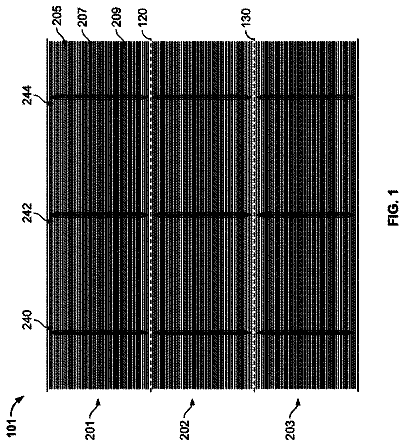
Some implementations provide a device (e.g., solar panel) that includes an active layer and a solar absorbance layer.
US 9,960,306 B2 · Assignee: PANASONIC INTELLECTUAL PROPERTY MANAGEMENT CO., LTD. · Inventors: Nakagawa; Tohru et al.
Sheet 1 of 28 from the published document. All sheets in the USPTO PDF
A condensing photoelectric conversion apparatus includes a first photoelectric conversion module and a second photoelectric conversion module. The first and second condensing photoelectric conversion modules each include a power generating element, a condensing lens located on the power generating element and having a front surface with a convex portion and a flat rear surface, a transparent first resin located between the power generating element and the rear surface of the condensing lens, a colored second resin located on the rear surface of the condensing lens and around the power generating element, and a third resin located between the condensing lens of the first photoelectric conversion module and the condensing lens of the second photoelectric conversion module, and having a refractive index n.sub.1 satisfying a relational expression n.sub.0−0.05≤n.sub.1≤n.sub.0+1.0 with a refractive index n.sub.0 of the condensing lens.
Patent Literature 1 discloses a conventional condensing photoelectric conversion apparatus having various outer colors. The condensing photoelectric conversion apparatus described in Patent Literature 1 includes a substrate and a plurality of disposed primary power generation structures integrally provided with the substrate. The primary power generation structures each have a power generating element provided on the substrate and configured to convert light to electricity, and a condensing lens provided above the power generating element. Each of the primary power generation structures has a color scheme member that is located on the substrate at a position different from that of the power generating element. The color scheme members of the primary power generation structures each function as a pixel so that the pixels in the entire apparatus form an image. CITATION LIST Patent Literatu
1 of 28 drawing sheets so far from the published document, cropped to the drawing. Every sheet is in the USPTO PDF.
What the patent claimed, word for word. All of it is now free to use.
The technical field relates to a condensing photoelectric conversion apparatus having a uniform outer color and a condensing photoelectric conversion system.
Patent Literature 1 discloses a conventional condensing photoelectric conversion apparatus having various outer colors. The condensing photoelectric conversion apparatus described in Patent Literature 1 includes a substrate and a plurality of disposed primary power generation structures integrally provided with the substrate. The primary power generation structures each have a power generating element provided on the substrate and configured to convert light to electricity, and a condensing lens provided above the power generating element. Each of the primary power generation structures has a color scheme member that is located on the substrate at a position different from that of the power generating element. The color scheme members of the primary power generation structures each function as a pixel so that the pixels in the entire apparatus form an image. CITATION LIST Patent Literature
Patent Literature 1:
In the conventional condensing photoelectric conversion apparatus, however, the color scheme members viewed through the condensing lens appear ununiform in color, in other words, the entire apparatus appears ununiform in color.
One non-limiting and exemplary embodiment provides a condensing photoelectric conversion apparatus having a uniform outer color and a condensing photoelectric conversion system including the condensing photoelectric conversion apparatus.
Additional benefits and advantages of the disclosed embodiments will be apparent from the specification and Figures. The benefits and/or advantages may be individually provided by the various embodiments and features of the specification and drawings disclosure, and need not all be provided in order to obtain one or more of the same.
In one general aspect, the techniques disclosed here feature: a condensing photoelectric conversion apparatus comprising:
a first photoelectric conversion module; and
a second photoelectric conversion module,
wherein the first photoelectric conversion module and the second photoelectric conversion module each comprise:
a power generating element,
a condensing lens located on the power generating element, the condensing lens having a front surface with a convex portion and a flat rear surface,
a transparent first resin located between the power generating element and the rear surface of the condensing lens,
a colored second resin located on the rear surface of the condensing lens and around the power generating element, and
a third resin located between the condensing lens of the first photoelectric conversion module and the condensing lens of the second photoelectric conversion module, the third resin having a refractive index n.sub.1 satisfying a relational expression n.sub.0−0.05≤n.sub.1≤n.sub.0+1.0 with a refractive index n.sub.0 of the condensing lens.
These general and specific aspects may be implemented using a system, a method, and a computer program, and any combination of systems, methods, and computer programs.
In the condensing photoelectric conversion apparatus and system according to the this aspect of the present disclosure, the resin having a refractive index satisfying the predetermined relational expression with the refractive index of the condensing lens is located between adjacent lens arrays. Scattering light exiting from the colored resin can efficiently reach an observer. Accordingly, an end of the photoelectric conversion module in the condensing photoelectric conversion apparatus and system hardly appears whiter than the remaining portion. The outer color of the condensing photoelectric conversion apparatus can be thus made substantially the same as the color of the colored resin provided in the photoelectric conversion module, and the outer color of the entire apparatus can be made uniform. Accordingly, the condensing photoelectric conversion apparatus and system can be designed in any color depending on the purpose of use.
These and other aspects and features of the present disclosure will become clear from the following description taken in conjunction with the embodiments thereof with reference to the accompanying drawings, in which:
FIG. 1A is a schematic perspective view of a condensing photoelectric conversion system including a condensing photoelectric conversion apparatus according to a first embodiment of the present disclosure;
FIG. 1B is a sectional view taken along line A-A in FIG. 1A , of the condensing photoelectric conversion apparatus according to the first embodiment of the present disclosure;
FIG. 1C is a schematic exploded perspective view of one of condensing photoelectric conversion modules in the condensing photoelectric conversion apparatus according to the first embodiment of the present disclosure;
FIG. 1D is a schematic sectional view of a minimum unit in the condensing photoelectric conversion apparatus according to the first embodiment of the present disclosure;
FIG. 2A is a schematic enlarged sectional view of the vicinity of a condensing lens of the condensing photoelectric conversion module according to the first embodiment of the present disclosure;
FIG. 2B is an enlarged sectional view of the condensing photoelectric conversion module shown in FIG. 2A , according to the first embodiment of the present disclosure;
FIG. 2C is a schematic plan view showing positional relation between a power generating element and a circuit board in a state where a lens array, a first resin, and a second resin are removed virtually in the condensing photoelectric conversion module according to the first embodiment of the present disclosure;
FIG. 3A is a schematic sectional view showing a method of producing the power generating element used in the condensing photoelectric conversion apparatus according to the first embodiment of the present disclosure;
FIG. 3B is a schematic sectional view showing a method of producing the power generating element used in the condensing photoelectric conversion apparatus according to the first embodiment of the present disclosure;
FIG. 3C is a schematic sectional view showing a method of producing the power generating element used in the condensing photoelectric conversion apparatus according to the first embodiment of the present disclosure;
FIG. 3D is a schematic sectional view showing a method of producing the power generating element used in the condensing photoelectric conversion apparatus according to the first embodiment of the present disclosure;
FIG. 3E is a schematic sectional view showing a method of producing the power generating element used in the condensing photoelectric conversion apparatus according to the first embodiment of the present disclosure;
FIG. 3F is a schematic sectional view showing a method of producing the power generating element used in the condensing photoelectric conversion apparatus according to the first embodiment of the present disclosure;
FIG. 3G is a schematic sectional view showing a method of producing the power generating element used in the condensing photoelectric conversion apparatus according to the first embodiment of the present disclosure;
FIG. 3H is a schematic sectional view of a power generating element produced by the method of producing the power generating element used in the condensing photoelectric conversion apparatus according to the first embodiment of the present disclosure;
FIG. 3I is a schematic plan view of a power generating element produced by the method of producing the power generating element used in the condensing photoelectric conversion apparatus according to the first embodiment of the present disclosure;
FIG. 4A is a schematic sectional view showing a state of a light ray reaching an observer who observes the condensing photoelectric conversion apparatus according to the first embodiment of the present disclosure;
FIG. 4B is a schematic sectional view showing a state of a light ray reaching an observer who observes the condensing photoelectric conversion apparatus according to the first embodiment of the present disclosure;
FIG. 4C is an enlarged view of a region 406 in FIG. 4A , showing a state of a light ray reaching an observer who observes the condensing photoelectric conversion apparatus according to the first embodiment of the present disclosure;
FIG. 4D is an enlarged view of a region 414 in FIG. 4B , showing a state of a light ray reaching an observer who observes the condensing photoelectric conversion apparatus according to the first embodiment of the present disclosure;
FIG. 4E is an enlarged view of a region 415 in FIG. 4B , showing a state of a light ray reaching an observer who observes the condensing photoelectric conversion apparatus according to the first embodiment of the present disclosure;
FIG. 5A is a schematic sectional view showing a state where a light ray passing through a third resin in a gap between two adjacent condensing photoelectric conversion modules reaches an observer who observes the condensing photoelectric conversion apparatus according to the first embodiment at a different angle;
FIG. 5B is a schematic sectional view showing a state where a light ray passing through the third resin in the gap between two adjacent condensing photoelectric conversion modules reaches an observer who observes the condensing photoelectric conversion apparatus according to the first embodiment at a different angle;
FIG. 6A is a graph indicating calculation results of a correlation between an observation angle and a relative intensity of light reaching an observer, from each of a comparative example of a condensing photoelectric conversion apparatus according to the first embodiment and a conventional condensing photoelectric conversion apparatus, in a case where the refractive index of the third resin is 1;
FIG. 6B is a graph indicating calculation results of a correlation between an observation angle and a relative intensity of light reaching an observer, from each of a comparative example of a condensing photoelectric conversion apparatus according to the first embodiment and a conventional condensing photoelectric conversion apparatus, in a case where the refractive index of the third resin is 1.40;
FIG. 6C is a graph indicating calculation results of a correlation between an observation angle and a relative intensity of light reaching an observer, from each of the condensing photoelectric conversion apparatus according to the first embodiment and the conventional condensing photoelectric conversion apparatus, in a case where the refractive index of the third resin is 1.44;
FIG. 6D is a graph indicating calculation results of a correlation between an observation angle and a relative intensity of light reaching an observer, from each of the condensing photoelectric conversion apparatus according to the first embodiment and the conventional condensing photoelectric conversion apparatus, in a case where the refractive index of the third resin is 1.47;
FIG. 7A is a graph indicating calculation results of a correlation between an observation angle and a relative intensity of light reaching an observer, from each of the condensing photoelectric conversion apparatus according to the first embodiment and the conventional condensing photoelectric conversion apparatus, in a case where the refractive index of the third resin is 1.56 that is larger than the refractive index of the lens;
FIG. 7B is a graph indicating calculation results of a correlation between an observation angle and a relative intensity of light reaching an observer, from each of the condensing photoelectric conversion apparatus according to the first embodiment and the conventional condensing photoelectric conversion apparatus, in a case where the refractive index of the third resin is 2.49 that is larger than the refractive index of the lens;
FIG. 7C is a graph indicating calculation results of a correlation between an observation angle and a relative intensity of light reaching an observer, from each of the comparative example of the condensing photoelectric conversion apparatus according to the first embodiment and the conventional condensing photoelectric conversion apparatus, in a case where the refractive index of the third resin is 2.69 that is larger than the refractive index of the lens;
FIG. 8 is a graph indicating calculation results of a correlation between an observation angle and a relative intensity of light reaching an observer, from each of the condensing photoelectric conversion apparatus according to the first embodiment and the conventional condensing photoelectric conversion apparatus, in a case where the refractive index of the lens is equal to the refractive index of the third resin;
FIG. 9A is a schematic enlarged sectional view of the vicinity of one of condensing lenses in a condensing photoelectric conversion apparatus according to a second embodiment of the present disclosure;
FIG. 9B is a schematic sectional view of a condensing photoelectric conversion module in the vicinity of a power generating element in the condensing photoelectric conversion apparatus according to the second embodiment of the present disclosure;
FIG. 9C is a schematic plan view of the condensing photoelectric conversion module in the condensing photoelectric conversion apparatus according to the second embodiment of the present disclosure, in a case where a substrate is removed virtually;
FIG. 10A is a schematic sectional view showing a method of producing the power generating element used in the condensing photoelectric conversion apparatus according to the second embodiment of the present disclosure;
FIG. 10B is a schematic sectional view showing a method of producing the power generating element used in the condensing photoelectric conversion apparatus according to the second embodiment of the present disclosure;
FIG. 10C is a schematic sectional view showing a method of producing the power generating element used in the condensing photoelectric conversion apparatus according to the second embodiment of the present disclosure;
FIG. 10D is a schematic sectional view showing a method of producing the power generating element used in the condensing photoelectric conversion apparatus according to the second embodiment of the present disclosure;
FIG. 10E is a schematic sectional view showing a method of producing the power generating element used in the condensing photoelectric conversion apparatus according to the second embodiment of the present disclosure;
FIG. 10F is a schematic sectional view showing a method of producing the power generating element used in the condensing photoelectric conversion apparatus according to the second embodiment of the present disclosure;
FIG. 10G is a schematic sectional view of a power generating element produced by the method of producing the power generating element used in the condensing photoelectric conversion apparatus according to the second embodiment of the present disclosure;
FIG. 10H is a schematic plan view of a power generating element produced by the method of producing the power generating element used in the condensing photoelectric conversion apparatus according to the second embodiment of the present disclosure;
FIG. 11A is a schematic perspective view of the condensing photoelectric conversion apparatus according to the second embodiment of the present disclosure;
FIG. 11B is a schematic sectional view taken along line A-A in FIG. 11A , of the condensing photoelectric conversion apparatus according to the second embodiment of the present disclosure;
FIG. 12A is a schematic sectional view showing a state before deterioration, of a condensing photoelectric conversion apparatus according to a third embodiment of the present disclosure;
FIG. 12B is a schematic sectional view showing a state after deterioration, of the condensing photoelectric conversion apparatus according to the third embodiment of the present disclosure;
FIG. 13A is a schematic sectional view showing a state before deterioration, of the condensing photoelectric conversion apparatus according to the third embodiment of the present disclosure;
FIG. 13B is a schematic sectional view showing a state after deterioration, of the condensing photoelectric conversion apparatus according to the third embodiment of the present disclosure;
FIG. 14A is a schematic perspective view showing a method of producing the condensing photoelectric conversion apparatus according to the third embodiment of the present disclosure;
FIG. 14B is a schematic perspective view showing a method of producing the condensing photoelectric conversion apparatus according to the third embodiment of the present disclosure;
FIG. 14C is a schematic perspective view showing a method of producing the condensing photoelectric conversion apparatus according to the third embodiment of the present disclosure;
FIG. 14D is a schematic perspective view showing a method of producing the condensing photoelectric conversion apparatus according to the third embodiment of the present disclosure;
FIG. 14E is a schematic sectional view taken along line A-A in FIG. 14D , of a condensing photoelectric conversion apparatus produced by the method of producing the condensing photoelectric conversion apparatus according to the third embodiment of the present disclosure;
FIG. 14F is a schematic view of a condensing photoelectric conversion system according to the third embodiment of the present disclosure;
FIG. 15A is a schematic perspective view showing a method of producing a condensing photoelectric conversion apparatus according to a fourth embodiment of the present disclosure;
FIG. 15B is a schematic perspective view showing a method of producing a condensing photoelectric conversion apparatus according to a fourth embodiment of the present disclosure;
FIG. 15C is a schematic perspective view showing the method of producing the condensing photoelectric conversion apparatus according to the fourth embodiment of the present disclosure;
FIG. 15D is a schematic perspective view of a condensing photoelectric conversion system according to the fourth embodiment of the present disclosure;
FIG. 16A is a schematic perspective view of a conventional condensing photoelectric conversion apparatus;
FIG. 16B is a schematic sectional view of a conventional condensing photoelectric conversion apparatus;
FIG. 16C is a schematic exploded perspective view of one of modules in the conventional condensing photoelectric conversion apparatus;
FIG. 17A is a schematic sectional view showing a state of a light ray reaching an observer who observes the conventional condensing photoelectric conversion apparatus;
FIG. 17B is a schematic sectional view showing a state of a light ray reaching an observer who observes the conventional condensing photoelectric conversion apparatus;
FIG. 17C is a schematic enlarged explanatory view of a region 1205 , showing a state of a light ray reaching an observer who observes the conventional condensing photoelectric conversion apparatus;
FIG. 17D is a schematic enlarged explanatory view of a region 1213 , showing a state of a light ray reaching an observer who observes the conventional condensing photoelectric conversion apparatus; and
FIG. 17E is a schematic enlarged explanatory view of a region 1214 , showing a state of a light ray reaching an observer who observes the conventional condensing photoelectric conversion apparatus.
(Finding as Basis of the Disclosure)
FIGS. 16A to 16C are schematic views of a condensing photoelectric conversion system and an condensing photoelectric conversion apparatus disclosed in Patent Literature 1. FIGS. 16A to 16C are not the same as those figures disclosed in Patent Literature 1, but correctly illustrate the features of the disclosure.
FIG. 16A is a schematic appearance view of a conventional condensing photoelectric conversion system 1110 . The system 1110 includes four condensing photoelectric conversion modules 1100 , frames 1102 supporting these modules, a pillar 1103 supporting the frames 1102 , and a base 1104 fixing the pillar 1103 . The four condensing photoelectric conversion modules 1100 and the frames 1102 supporting these modules are collectively referred to as a “condensing photoelectric conversion apparatus”. Although not shown in FIG. 16A , the condensing photoelectric conversion system is equipped with a drive unit configured to move a condensing photoelectric conversion apparatus 1109 such that the condensing photoelectric conversion apparatus 1109 faces the sun.
FIG. 16B is a schematic sectional view taken along line A-A, of the two condensing photoelectric conversion apparatuses 1109 . As shown in this figure, the condensing photoelectric conversion modules 1100 each include a lens array 1101 configured to condense sunlight, power generating elements 1106 , a box 1105 , and a colored portion 1107 . The power generating elements 1106 are fixed to a flat portion of the box 1105 . The portion other than the power generating elements 1106 in the flat portion of the box 1105 is colored to configure the colored portion 1107 . The lens array 1101 is fixed to the top of the box 1105 .
FIG. 16C is a schematic exploded view of the condensing photoelectric conversion module 1100 . As shown in FIG. 16C , the lens array 1101 includes 16 condensing lenses 1108 , for example. The power generating elements 1106 are located respectively at focal positions of the condensing lenses 1108 . When sunlight vertically enters the lens array 1101 , the sunlight condensed by the lenses 1108 is applied respectively to the power generating elements 1106 . The power generating elements 1106 convert sunlight energy thus received to electrical energy.
The colored portion 1107 is provided around the power generating elements 1106 . When the condensing photoelectric conversion module 1100 is viewed obliquely, the color of the colored portion 1107 is recognized. Such an oblique direction is not perpendicular to the surface of the lens array 1101 included in the condensing photoelectric conversion module 1100 (e.g. 45 degrees).
The colored portion 1107 has no influence on the power generation function of the condensing photoelectric conversion apparatus.
Problems of a conventional condensing photoelectric conversion apparatus are described with reference to FIGS. 17A and 17B .
FIGS. 17A and 17B are schematic sectional views of a condensing photoelectric conversion apparatus, illustrating how a color of the vicinity of a lens 1202 of a condensing photoelectric conversion module 1101 appears to an observer 1200 and how a color of the vicinity of a lens 1210 appears to an observer 1208 , respectively. FIGS. 17A and 17B do not show a base 1102 fixing the condensing photoelectric conversion module 1101 . While description is made with reference to these two figures for easier understanding, the observer 1200 is actually identical with the observer 1208 and this single observer simultaneously observes the vicinities of the lens 1202 and the lens 1210 .
FIG. 17A initially shows how the vicinity of the lens 1202 of the condensing photoelectric conversion module 1101 appears. Scattering light 1203 exits from one point in the colored portion 1107 in the condensing photoelectric conversion module 1101 , and a light ray 1204 as part of the scattering light 1203 travels toward the observer 1200 . This light ray passes through a surrounded region 1205 in the lens 1202 and reaches the observer 1200 as a light ray 1206 . FIG. 17C is an enlarged view of the region 1205 . As shown in FIG. 17C , the light ray 1204 is reflected twice, i.e., by the lens 1202 and an air interface. Light rays reflected by these interfaces are referred to as a light ray 1217 and a light ray 1218 , respectively. The remaining light ray 1206 obtained by removing the reflected light rays 1217 and 1218 from the light ray 1204 reaches the observer 1200 . The light ray 1204 reaches the observer 1200 with an intensity weaker than that of a case where the lens 1202 is not provided. The observer 1200 observing the light ray 1206 regards the portion of the lens 1202 as being colored. The observer 1200 also receives a light ray 1207 reflected by the lens 1202 . The light ray 1207 includes all the wavelengths of sunlight, and the observer 1200 thus regards the light ray 1207 as being white. The observer 1200 accordingly regards the color of the lens 1202 as a mixture of the color of the colored portion 1107 and white. As the light ray 1204 is reflected larger in the region 1205 , the color of the lens 1202 will appear in a color close to white.
FIG. 17B shows appearance of the vicinity of the lens 1210 at the left end (closer to the other module) of one of the two adjacent condensing photoelectric conversion modules 1101 . A light ray 1212 in scattering light 1211 exiting from the colored portion 1107 travels toward the observer 1208 . The light ray 1212 passes through two regions 1213 and 1214 and then reaches the observer 1208 as a light ray 1215 . FIG. 17D is an enlarged view of the region 1213 . FIG. 17E is an enlarged view of the region 1214 . As shown in these figures, the light ray 1212 is reflected six times in total until the light ray 1212 reaches the observer 1208 . The scattering light ray 1212 exiting from the colored portion 1107 and reaching the observer 1208 has an intensity weaker than that of a case where no lens is provided. The observer 1208 also receives a light ray 1216 reflected by the lens 1210 . The light ray 1216 includes all the wavelengths of sunlight, and thus appears white to the observer 1208 . The observer 1208 accordingly regards the color of the lens 1210 as a mixture of the color of the colored portion 1107 and white. As a light ray is reflected larger in the two regions 1213 and 1214 , the color of the lens 1210 appears whiter.
The number of reflection of the scattering light ray 1212 in FIG. 17B is larger than the number of reflection of the scattering light ray 1204 in FIG. 17A . The lens 1210 appears whiter than the lens 1202 to the observer 1208 . In the condensing photoelectric conversion apparatus, the end of the condensing photoelectric conversion module 1101 thus appears whiter than the center. The condensing photoelectric conversion apparatus accordingly appears ununiform in color. As described above, the conventional condensing photoelectric conversion module 1101 causes the entire apparatus to appear ununiform in color.
FIGS. 17A and 17B show only cases where the lenses 1202 and 1210 are observed at angles 1201 and 1209 , respectively. Also in cases where other lenses are observed at various angles, these lenses each appear in a color obtained by adding white to the color of the colored portion 1107 . Furthermore, the entire apparatus appears ununiform in color.
In view of the above, the inventors of the present disclosure studied eagerly to find that the condensing photoelectric conversion apparatus according to the present disclosure entirely appears more uniform in outer color than the conventional condensing photoelectric conversion apparatus when a third resin 107 having a refractive index substantially equal to that of the lens array is provided in a gap between the adjacent condensing photoelectric conversion modules. The present disclosure has been thus achieved.
Embodiments of the present disclosure are described below with reference to the accompanying drawings.
Before the detailed description of the embodiments of the present disclosure with reference to the drawings, various aspects of the present disclosure are described.
Examples of the disclosed technique are as follows.
1st aspect: A condensing photoelectric conversion apparatus comprising:
a first photoelectric conversion module; and
a second photoelectric conversion module,
wherein the first photoelectric conversion module and the second photoelectric conversion module each comprise:
a power generating element,
a condensing lens located on the power generating element, the condensing lens having a front surface with a convex portion and a flat rear surface,
a transparent first resin located between the power generating element and the rear surface of the condensing lens,
a colored second resin located on the rear surface of the condensing lens and around the power generating element, and
a third resin located between the condensing lens of the first photoelectric conversion module and the condensing lens of the second photoelectric conversion module, the third resin having a refractive index n.sub.1 satisfying a relational expression n.sub.0−0.05≤n.sub.1≤n.sub.0+1.0 with a refractive index n.sub.0 of the condensing lens.
According to this aspect, the outer color of the condensing photoelectric conversion apparatus can be made substantially the same as the color of the colored resin provided in the photoelectric conversion module, and the outer color of the entire apparatus can be made uniform. The condensing photoelectric conversion apparatus can be thus designed in any color depending on the purpose of use.
2nd aspect: The condensing photoelectric conversion apparatus according to 1st aspect, wherein
the refractive index n.sub.1 of the third resin and the refractive index n.sub.0 of the condensing lens satisfy a relational expression n.sub.0≤n.sub.1≤n.sub.0+1.0.
According to this aspect, the outer color is uniform more reliably even at a small observation angle.
3rd aspect: The condensing photoelectric conversion apparatus according to 1st or 2nd aspect, wherein the second resin is a resin into which a pigment or a dye is mixed
According to this aspect, scattering light from the third resin also reaches an observer. The condensing photoelectric conversion apparatus thus appears more uniform in outer color.
4th aspect: The condensing photoelectric conversion apparatus according to 1st or 2nd aspect, wherein the second resin is a resin containing a luminous agent.
According to this aspect, the second resin contains the luminous agent so as to be luminous at night. The apparatus can function as a lighting device at a location with no street lamp.
5th aspect: The condensing photoelectric conversion apparatus according to 1st or 2nd aspect, wherein the third resin is made of a material identical to a material for the second resin.
According to this aspect, scattering light from the third resin also reaches an observer. The condensing photoelectric conversion apparatus thus appears more uniform in outer color.
6th aspect: The condensing photoelectric conversion apparatus according to 1st or 2nd aspect, wherein the third resin is in contact with a silicone-based oil, and the silicone-based oil is located on the flat rear surface of the condensing lens.
According to this aspect, the silicone-based oil enters a gap or the like formed by deterioration of the third resin or the like due to surface tension to fill the gap or the like in the third resin. This configuration prevents decrease in uniformity of the outer color due to the gap or the like formed by deterioration of the third resin.
7th aspect: The condensing photoelectric conversion apparatus according to 6th aspect, wherein the silicone-based oil is a fluorine-modified silicone oil.
According to this aspect, when the silicone-based oil is a fluorine-modified silicone oil having small surface tension, such a silicone oil is more likely to enter a crack, a cavity, or the like in the gap in the third resin.
8th aspect: A condensing photoelectric conversion system comprising:
the condensing photoelectric conversion apparatus according to 1st or 2nd aspect; and
a drive unit configured to drive the condensing photoelectric conversion apparatus.
According to this aspect, the outer color of the condensing photoelectric conversion apparatus can be made substantially the same as the color of the colored resin provided in the photoelectric conversion module, and the outer color of the entire apparatus can be made uniform. The condensing photoelectric conversion apparatus can be thus designed in any color depending on the purpose of use.
Embodiments of the present disclosure are described below with reference to the accompanying drawings. First Embodiment
A condensing photoelectric conversion system 111 including a condensing photoelectric conversion apparatus 110 according to the first embodiment is summarized initially, and the condensing photoelectric conversion apparatus 110 is then described in detail.
FIGS. 1A to 1C are schematic views summarizing the condensing photoelectric conversion apparatus 110 and the condensing photoelectric conversion system 111 according to the first embodiment.
FIG. 1A is a schematic view of the condensing photoelectric conversion system 111 .
The condensing photoelectric conversion system 111 includes the condensing photoelectric conversion apparatus 110 , a support bar 108 supporting the condensing photoelectric conversion apparatus 110 , and a drive unit 99 configured to move the condensing photoelectric conversion apparatus 110 relatively to the support bar 108 .
The condensing photoelectric conversion apparatus 110 includes a plurality of (for example, four in FIG. 1A ) condensing photoelectric conversion modules 100 , and a base 106 supporting the condensing photoelectric conversion modules 100 . All of the condensing photoelectric conversion modules 100 are located on the flat base 106 and are planarly fixed thereto. FIG. 1A exemplifies a case where the four condensing photoelectric conversion modules 100 each having a square shape are located adjacently and fixed onto the base 106 having a square shape. The adjacent condensing photoelectric conversion modules 100 have a minute gap 91 therebetween.
The drive unit 99 drives the condensing photoelectric conversion apparatus 110 so that the condensing photoelectric conversion apparatus 110 constantly faces the sun. The drive unit 99 is composed of a tracking drive unit, for example. The tracking drive unit is composed of a horizontal rotation drive unit and an elevation angle rotation drive unit, each being composed of any motor such as a DC motor, an AC motor, or a stepping motor and a hydraulic control mechanism, for example.
The drive unit 99 may include a light detector. The horizontal rotation drive unit rotates the condensing photoelectric conversion apparatus integrally with the light detector to the east or to the west in the horizontal direction toward the sun about a horizontal rotation axis. The elevation angle rotation drive unit similarly rotates the condensing photoelectric conversion apparatus integrally with the light detector to the south or to the north in the elevation angle direction toward the sun about an elevation angle rotation axis. The tracking drive unit is drive-controlled by a controller. The controller drive-controls the tracking drive unit in accordance with information on a detection result of the light detector, time information on sunrise and sunset which statistically differs in seasons, time information, and the like. In a case where the light detector is not provided, the controller drive-controls the tracking drive unit in accordance with time information on sunrise and sunset, time information, and the like.
Each of the condensing photoelectric conversion modules 100 includes power generating elements 103 , condensing lenses 109 , a transparent first resin 102 , a colored second resin 104 , and a third resin 107 .
FIG. 1B is a schematic sectional view taken along line A-A in FIG. 1A . FIG. 10 is a schematic exploded view of one of the condensing photoelectric conversion modules 100 . As shown in FIG. 1B , each of the condensing photoelectric conversion modules 100 includes the condensing lenses 101 , the power generating elements 103 located respectively below the condensing lenses 101 , the transparent first resin 102 located between the lower surfaces (rear surfaces) of the condensing lenses 101 and the power generating elements 103 , and the colored second resin 104 located below the condensing lenses 101 . In FIG. 1B , each of the condensing photoelectric conversion modules 100 further includes a circuit board 105 .
The circuit board 105 is provided with electrodes (not shown) which are electrically connected to electrodes of the power generating elements 103 . The circuit board 105 is in contact with the colored second resin 104 .
As exemplified in FIG. 10 , nine power generating elements 103 are located respectively at positions near focal points of nine condensing lenses 109 configuring a lens array 101 . Sunlight condensed by the condensing lens 109 is applied to the corresponding power generating element 103 , which generates electrical power. The colored second resin 104 is located around the power generating elements 103 . The colored second resin 104 is provided in a flat portion (a planar region) on the rear surface of the lens array 101 except for the region of the transparent first resin 102 .
As shown in FIGS. 1A and 1B , the gap 91 between the adjacent lens arrays 101 is provided with the third resin 107 . As to be described in detail later, the third resin 107 has a refractive index that is substantially equal to the refractive index of a material for the lens arrays 101 or is in a range satisfying a predetermined expression to be described later.
Described in detail next is the configuration of each of the condensing photoelectric conversion modules 100 in the condensing photoelectric conversion apparatus 110 according to the first embodiment.
<Condensing Lens 109 >
The lenses including the plurality of condensing lenses 109 are also referred to as the lens array 101 . The plurality of condensing lenses 109 are located on an identical plane, for example. As one example of each of the condensing photoelectric conversion modules 100 has no gaps between the plurality of condensing lenses 109 .
Each of the condensing lenses 109 is located on the first resin 102 and the second resin 104 .
The condensing lenses 109 each have a front surface with a convex portion and a flat rear surface. The rear surface of the condensing lens 109 is in contact with the first resin 102 and the second resin 104 . The rear surface of the condensing lens 109 has a condensing region and a colored region (other than the condensing region) not including a focal point of light incident on the convex portion on the front surface. The condensing region includes a region, in the rear surface of the condensing lens 109 , where light incident on the condensing lens 109 and condensed by the convex portion on the front surface passes through.
The region where condensed light passes through in the rear surface of the condensing lens 109 is previously designed in accordance with the condensing lens 109 and the wavelength of incident light. The condensing region may include, in addition to the region where condensed light passes through, a position distant by a predetermined distance or less from the condensing region. As one example of the predetermined distance depends on a production error of the condensing lens 109 or the like. Energy of light passing through the desirably exemplified condensing region is 95% or more and less than 100% of energy of light passing through the rear surface of the condensing lens 109 . Light not incident on the power generating element 103 can be reduced in amount even in a case where light passes through a region displaced from the previously designed region where light passes through in the rear surface of the condensing lens 109 due to a tracking error of the condensing photoelectric conversion apparatus 110 .
The description continues in the full USPTO document.
About 6,210 words. The USPTO PDF has it with every drawing.
Fees are due 3.5, 7.5 and 11.5 years after grant. This patent expired on May 1, 2026, so the fee marked "not paid" was the one that went unpaid.
CONDENSING PHOTOELECTRIC CONVERSION APPARATUS AND SYSTEM
Filed Apr 2015 · published Jul 2015Condensing photoelectric conversion apparatus and system
Filed Apr 2015 · granted May 2018Earlier publications, parents and continuations. None of them can still be enforced, or this patent would not be listed.
Prior art cited by the examiner or applicant. Useful when you check your own idea for novelty.
Everything on this page comes from the documents linked above.