Background of the invention
The present invention relates generally to rapid, non-destructive, selective infrared spectrometry analysis of organic coatings on molded articles. More particularly, the invention relates to such analysis of sub-micron coatings and mold lubricant residues on disposable thermoplastic medical articles such as syringes, auto-injector cartridges, and vials used to contain, store, or deliver pharmaceutical agents, body fluids, diagnostic reagents, and other fluid materials.
The present invention also relates to a pharmaceutical package or other container and to a method for coating or layering an inner or interior surface of a pharmaceutical package or other container. The present invention also relates more generally to medical devices, including devices other than packages or containers, for example catheters.
The present disclosure also relates to improved methods for processing pharmaceutical packages or other containers, for example multiple identical pharmaceutical packages or other containers used for pharmaceutical preparation storage and delivery, venipuncture and other medical sample collection, and other purposes. Such pharmaceutical packages or other containers are used in large numbers for these purposes, and must be relatively economical to manufacture and yet highly reliable in storage and use.
One important consideration in manufacturing pre-filled syringes and cartridges or other containers (such as vials) for storing or other contact with fluids, for example, is that the contents of the pharmaceutical package or other container desirably will have a substantial shelf life. During this shelf life, it is important to isolate the material filling the pharmaceutical package or other container from the container wall containing it, or from a barrier coating or layer or other functional coatings or layers applied to the pharmaceutical package or other container wall to avoid leaching material from the pharmaceutical package or other container wall, barrier coating or layer, or other functional coatings or layers into the prefilled contents or vice versa.
Commonly, after it is filled, a prefilled syringe or cartridge is capped at the distal end, as with a needle shield or other type of cap, and is closed at the proximal end by its drawn plunger tip or piston. The prefilled syringe or cartridge can be wrapped in a sterile package before use. To use the prefilled syringe or cartridge, the packaging and needle shield or other type of cap are removed, optionally a hypodermic needle or other type of dispenser is attached (if not already present), the delivery conduit or syringe is moved to a use position (such as by inserting the hypodermic needle into a patient's blood container or into apparatus to be rinsed with the contents of the syringe), and the plunger tip or piston is advanced in the barrel to inject the contents of the barrel. If a cartridge is being used, it is also placed into a mechanism that mechanically advances the piston to make an injection, for example using an injection spring.
Another important consideration is reliability of manufacture of pre-filled syringes, cartridges, vials, or other containers for storing or otherwise contacting injectable pharmaceutical materials and other fluids. Since many of these containers are inexpensive and used in large quantities, for certain applications it will be useful to reliably obtain the necessary shelf life without increasing the manufacturing cost to a prohibitive level. To address this need, it will be useful to develop rapid, inexpensive inspection methods that can be used to non-destructively inspect each container manufactured for any defects that may impact on its performance. For example, the coatings applied to thermoplastic containers to improve their barrier properties and prevent interaction of fluid contents with the container are desirably inspected before filling the containers with a costly medication or diagnostic material.
Traditional infrared (IR) spectrometry methods for detection of submicron coatings are IR reflectance methods, such as Fourier Transform Infrared-Attenuated Total Reflectance (FTIR-ATR). These methods require contact of the coating with an ATR crystal having a flat surface, typically made of sapphire. As a consequence, non-flat coated substrates (e.g. vials, syringe barrels) must be cut into small sections and compressed onto this sapphire stage for measurement, which is a destructive test. Also, contact of the coating surface to the spectrometer sapphire window is required, which can affect the coating.
These methods will tend to damage the coating, and thus are undesirable for inspection of the actual containers to be filled with a pharmaceutical or diagnostic material and distributed for medical use.
Summary of the invention
An aspect of the invention is a non-destructive method of detecting whether a coating or deposit of SiO.sub.xC.sub.y or SiN.sub.xC.sub.y, where x can be from about 0.5 to about 2.4 and y can be from about 0.6 to about 3, is present on or near a surface of an article. The method includes impinging, collecting, and measuring steps.
The impinging step includes impinging infrared light having a wave number in one or more of (a) at least a portion of a range between 950 and 1230 cm.sup.−1 and (b) at least a portion of a range between 1230 and 1300 cm.sup.−1, for example from a source, onto at least a first surface being examined for the presence of a coating or deposit of SiO.sub.xC.sub.y or SiN.sub.xC.sub.y.
The collecting step includes collecting at least a portion of the infrared light impinged on the first surface, as with a collector.
The measuring step includes measuring the response output, which may include for example the maximum intensity and/or peak area of the collected infrared light at an infrared spectroscopy peak, in one or more of (a) at least a portion of a range between 950 and 1230 cm.sup.−1 and (b) at least a portion of a range between 1230 and 1300 cm.sup.−1. For example, the coating or deposit of SiO.sub.xC.sub.y or SiN.sub.xC.sub.y can be indicated by an infrared spectroscopy peak in the wave number range of one or more of (a) at least a portion of a range from about 1015 to about 1035 cm.sup.−1 and (b) at least a portion of a range from about 1245 to about 1270 cm.sup.−1, each being indicative of a coating or deposit of SiO.sub.xC.sub.y or SiN.sub.xC.sub.y.
Still another aspect of the invention is a method of treating an article with coatings or deposits. An article including a first surface can be provided. A coating or deposit of SiO.sub.xC.sub.y or SiN.sub.xC.sub.y, where x can be from about 0.5 to about 2.4 and y can be from about 0.6 to about 3, can be applied on the first surface. The coating or deposit of SiO.sub.xC.sub.y or SiN.sub.xC.sub.y is generally from 5 to 200 nm thick, optionally from 5 to 100 nm thick, and optionally from 5 to 20 nm thick. A coating of SiO.sub.x, in which x can be from about 1.5 to about 2.9, can be applied over the coating or deposit of SiO.sub.xC.sub.y or SiN.sub.xC.sub.y. The coating or deposit of SiO.sub.xC.sub.y or SiN.sub.xC.sub.y, measured in the presence of the first surface and in the presence of the coating or deposit of SiO.sub.x, can be distinguished by a detectable response, such as an infrared spectroscopy peak, in one or more of (a) at least a portion of a range between 950 and 1230 cm.sup.−1 and (b) at least a portion of a range between 1230 and 1300 cm.sup.−1, indicative of a coating or deposit of SiO.sub.xC.sub.y or SiN.sub.xC.sub.y. For example, the coating or deposit of SiO.sub.xC.sub.y or SiN.sub.xC.sub.y, measured in the presence of the first surface and in the presence of the coating or deposit of SiO.sub.x, can be distinguished by a detectable infrared spectroscopy peak in the wave number range of one or more of (a) at least a portion of a range from about 1015 to about 1035 cm.sup.−1 and (b) at least a portion of a range from about 1245 to about 1270 cm.sup.−1, each being indicative of a coating or deposit of SiO.sub.xC.sub.y or SiN.sub.xC.sub.y.
Another aspect of the invention is a non-destructive method of detecting whether a coating or deposit of SiO.sub.x, where x is from about 1.5 to about 2.9, is present on or near a surface of an article. The method includes impinging, collecting, and measuring steps.
The impinging step includes impinging infrared light having a wave number in at least a portion of the range from about 1060 to about 1080 cm.sup.−1, for example from a source, onto at least a first surface being examined for the presence of a coating or deposit of SiO.sub.x.
The collecting step includes collecting at least a portion of the infrared light impinged on the first surface, as with a collector.
The measuring step includes measuring the response output, which may include for example the maximum intensity and/or peak area of the collected infrared light at an infrared spectroscopy peak, in at least a portion of the range from about 1060 to about 1080 cm.sup.−1.
Still another aspect of the invention is a method of treating an article with coatings or deposits. An article including a first surface can be provided. A coating or deposit of SiO.sub.x, in which x can be from about 1.5 to about 2.9, can be applied directly or indirectly on the first surface. The coating or deposit of SiO.sub.x is generally from 2 to 1000 nm thick, optionally from 10 to 200 nm thick, optionally from 20 to 200 nm thick, and optionally from 20 to 30 nm thick. A coating of SiO.sub.xC.sub.y or SiN.sub.xC.sub.y, where x can be from about 0.5 to about 2.4 and y can be from about 0.6 to about 3, can be applied over the coating or deposit of SiO.sub.x. The coating or deposit of SiO.sub.x, measured in the presence of the first surface and in the presence of the coating or deposit of SiO.sub.xC.sub.y or SiN.sub.xC.sub.y, can be distinguished by a detectable response, such as an infrared spectroscopy peak in the wave number range from about 1060 to about 1080 cm.sup.−1, indicative of a coating or deposit of SiO.sub.x.
Another aspect of the invention is a method of detecting one or more coatings or deposits that are each simultaneously distinguishable through infrared spectroscopy.
For example, an article including a first surface can be provided. A coating or deposit of SiO.sub.xC.sub.y or SiN.sub.xC.sub.y, where x can be from about 0.5 to about 2.4 and y can be from about 0.6 to about 3, can be applied on the first surface. A coating of SiO.sub.x, in which x can be from about 1.5 to about 2.9, can be applied over the coating or deposit of SiO.sub.xC.sub.y or SiN.sub.xC.sub.y. The coating or deposit of SiO.sub.x, measured in the presence of the first surface and in the presence of the coating or deposit of SiO.sub.xC.sub.y or SiN.sub.xC.sub.y, can be distinguished by a detectable response, such as an infrared spectroscopy peak in the wave number range from about 1060 to about 1080 cm.sup.−1, indicative of a coating or deposit of SiO.sub.x. At the same time, the coating or deposit of SiO.sub.xC.sub.y or SiN.sub.xC.sub.y, measured in the presence of the first surface and in the presence of the coating or deposit of SiO.sub.x, can be distinguished by a response in one or more of (a) at least a portion of a range between 950 and 1230 cm.sup.−1 and (b) at least a portion of a range between 1230 and 1300 cm.sup.−1, indicative of a coating or deposit of SiO.sub.xC.sub.y or SiN.sub.xC.sub.y. For example, the coating or deposit of SiO.sub.xC.sub.y or SiN.sub.xC.sub.y, measured in the presence of the first surface and in the presence of the coating or deposit of SiO.sub.x, can be distinguished by a detectable infrared spectroscopy peak 234 in the wave number range of one or more of (a) at least a portion of a range from about 1015 to about 1035 cm.sup.−1 and (b) at least a portion of a range from about 1245 to about 1270 cm.sup.−1, each being indicative of a coating or deposit of SiO.sub.xC.sub.y or SiN.sub.xC.sub.y.
As still another example, an article including a first surface can be provided. A coating or deposit of SiO.sub.x, in which x can be from about 1.5 to about 2.9, can be applied directly or indirectly on the first surface. A coating of SiO.sub.xC.sub.y or SiN.sub.xC.sub.y, where x can be from about 0.5 to about 2.4 and y can be from about 0.6 to about 3, can be applied over the coating or deposit of SiO.sub.x. The coating of SiO.sub.xC.sub.y or SiN.sub.xC.sub.y is generally from 10 to 1000 nm thick, optionally from 50 to 500 nm thick, and optionally from 100 to 200 nm thick. The coating or deposit of SiO.sub.x, measured in the presence of the first surface and in the presence of the coating or deposit of SiO.sub.xC.sub.y or SiN.sub.xC.sub.y, can be distinguished by a detectable response, such as an infrared spectroscopy peak in the wave number range from about 1060 to about 1080 cm.sup.−1, indicative of a coating or deposit of SiO.sub.x. At the same time, the coating or deposit of SiO.sub.xC.sub.y or SiN.sub.xC.sub.y, measured in the presence of the first surface and in the presence of the coating or deposit of SiO.sub.x, can be distinguished by a response in one or more of (a) at least a portion of a range between 950 and 1230 cm.sup.−1 and (b) at least a portion of a range between 1230 and 1300 cm.sup.−1, indicative of a coating or deposit of SiO.sub.xC.sub.y or SiN.sub.xC.sub.y. For example, the coating or deposit of SiO.sub.xC.sub.y or SiN.sub.xC.sub.y, measured in the presence of the first surface and in the presence of the coating or deposit of SiO.sub.x, can be distinguished by a detectable infrared spectroscopy peak in the wave number range of one or more of (a) at least a portion of a range from about 1015 to about 1035 cm.sup.−1 and (b) at least a portion of a range from about 1245 to about 1270 cm.sup.−1, each being indicative of a coating or deposit of SiO.sub.xC.sub.y or SiN.sub.xC.sub.y.
Another aspect of the invention is a method of treating an article with coatings or deposits and rapidly and non-destructively detecting the presence of one or more of the coatings or deposits.
For example, an article including a first surface can be provided. A first coating of SiO.sub.xC.sub.y or SiN.sub.xC.sub.y, where x is from about 0.5 to about 2.4 and y is from about 0.6 to about 3, can be applied on the first surface. The coating can then be detected by impinging infrared light having a wave number in one or more of (a) at least a portion of a range between 950 and 1230 cm.sup.−1 and (b) at least a portion of a range between 1230 and 1300 cm.sup.−1 onto at least a first surface being examined for the presence of a coating or deposit of SiO.sub.xC.sub.y or SiN.sub.xC.sub.y; collecting at least a portion of the infrared light impinged on the first surface; and measuring the response output, which may include for example the maximum intensity and/or peak area of the collected infrared light at an infrared spectroscopy peak, in one or more of (a) at least a portion of a range between 950 and 1230 cm.sup.−1 and (b) at least a portion of a range between 1230 and 1300 cm.sup.−1, indicative of a coating or deposit of SiO.sub.xC.sub.y or SiN.sub.xC.sub.y. For example, the coating or deposit of SiO.sub.xC.sub.y or SiN.sub.xC.sub.y can be distinguished by a detectable infrared spectroscopy peak in the wave number range of one or more of (a) at least a portion of a range from about 1015 to about 1035 cm.sup.−1 and (b) at least a portion of a range from about 1245 to about 1270 cm.sup.−1, each being indicative of a coating or deposit of SiO.sub.xC.sub.y or SiN.sub.xC.sub.y.
Next, a second coating from 5 to 1000 nm thick of SiO.sub.x, where x is from about 1.5 to about 2.9, can be applied over the first coating. And a third coating from 5 to 1000 nm thick of SiO.sub.xC.sub.y or SiN.sub.xC.sub.y, where x is from about 0.5 to about 2.4 and y is from about 0.6 to about 3, can be applied over the coating of SiO.sub.x. The second and third coatings can then be detected by impinging infrared light having a wave number in (a) at least a portion of a range from about 1060 to about 1080 cm.sup.−1, and (b) one or more of (i) at least a portion of a range between 950 and 1230 cm.sup.−1 and (ii) at least a portion of a range between 1230 and 1300 cm.sup.−1 onto at least a first surface being examined for the presence of the second and the third coatings; collecting at least a portion of the infrared light impinged on the first surface; and measuring the response output, which may include for example the maximum intensity and/or peak area of the collected infrared light at an infrared spectroscopy peak in at least a portion of the range from about 1060 to about 1080 cm.sup.−1, indicative of a coating or deposit of SiO.sub.x; and at the same time measuring the response output, which may include for example the maximum intensity and/or peak area of the collected infrared light at an infrared spectroscopy peak, in one or more of (a) at least a portion of a range between 950 and 1230 cm.sup.−1 and (b) at least a portion of a range between 1230 and 1300 cm.sup.−1, indicative of a coating or deposit of SiO.sub.xC.sub.y or SiN.sub.xC.sub.y, and optionally adjusting the measurement in order to account for the response output attributable to the first coating. For example, the coating or deposit of SiO.sub.xC.sub.y or SiN.sub.xC.sub.y can be distinguished by a detectable infrared spectroscopy peak in the wave number range of one or more of (a) at least a portion of a range from about 1015 to about 1035 cm.sup.−1 and (b) at least a portion of a range from about 1245 to about 1270 cm.sup.−1, each being indicative of a coating or deposit of SiO.sub.xC.sub.y or SiN.sub.xC.sub.y.
As another example, an article including a first surface can be provided. A first coating of SiO.sub.xC.sub.y or SiN.sub.xC.sub.y, where x is from about 0.5 to about 2.4 and y is from about 0.6 to about 3, can be applied on the first surface. Next, a second coating from 5 to 1000 nm thick of SiO.sub.x, where x is from about 1.5 to about 2.9, can be applied over the first coating. The first and second coatings can then be detected by impinging infrared light having a wave number in (a) at least a portion of a range from about 1060 to about 1080 cm.sup.−1, and (b) one or more of (i) at least a portion of a range between 950 and 1230 cm.sup.−1 and (ii) at least a portion of a range between 1230 and 1300 cm.sup.−1 onto at least a first surface being examined for the presence of the second and the third coatings; collecting at least a portion of the infrared light impinged on the first surface; and measuring the response output, which may include for example the maximum intensity and/or peak area of the collected infrared light at an infrared spectroscopy peak, in one or more of (a) at least a portion of a range between 950 and 1230 cm.sup.−1 and (b) at least a portion of a range between 1230 and 1300 cm.sup.−1, indicative of a coating or deposit of SiO.sub.xC.sub.y or SiN.sub.xC.sub.y; and at the same time measuring the response output, which may include for example the maximum intensity and/or peak area of the collected infrared light at an infrared spectroscopy peak, in at least a portion of the range from about 1060 to about 1080 cm.sup.−1, indicative of a coating or deposit of SiO.sub.x. For example, the coating or deposit of SiO.sub.xC.sub.y or SiN.sub.xC.sub.y can be distinguished by a detectable infrared spectroscopy peak in the wave number range of one or more of (a) at least a portion of a range from about 1015 to about 1035 cm.sup.−1 and (b) at least a portion of a range from about 1245 to about 1270 cm.sup.−1, each being indicative of a coating or deposit of SiO.sub.xC.sub.y or SiN.sub.xC.sub.y.
Next, a third coating of SiO.sub.xC.sub.y or SiN.sub.xC.sub.y, where x is from about 0.5 to about 2.4 and y is from about 0.6 to about 3, can be applied over the coating of SiO.sub.x. The third coating can then be detected by impinging infrared light having a wave number in one or more of (a) at least a portion of a range between 950 and 1230 cm.sup.−1 and (b) at least a portion of a range between 1230 and 1300 cm.sup.−1 onto at least a first surface being examined for the presence of a coating or deposit of SiO.sub.xC.sub.y or SiN.sub.xC.sub.y; collecting at least a portion of the infrared light impinged on the first surface; and measuring the response output, which may include for example the maximum intensity and/or peak area of the collected infrared light at an infrared spectroscopy peak, in one or more of (a) at least a portion of a range between 950 and 1230 cm.sup.−1 and (b) at least a portion of a range between 1230 and 1300 cm.sup.−1, indicative of a coating or deposit of SiO.sub.xC.sub.y or SiN.sub.xC.sub.y, and optionally adjusting the measurement in order to account for the response output attributable to the first coating. For example, the coating or deposit of SiO.sub.xC.sub.y or SiN.sub.xC.sub.y can be distinguished by a detectable infrared spectroscopy peak in the wave number range of one or more of (a) at least a portion of a range from about 1015 to about 1035 cm.sup.−1 and (b) at least a portion of a range from about 1245 to about 1270 cm.sup.−1, each being indicative of a coating or deposit of SiO.sub.xC.sub.y or SiN.sub.xC.sub.y.
As another example, an article including a first surface can be provided. A first coating of SiO.sub.xC.sub.y or SiN.sub.xC.sub.y, where x is from about 0.5 to about 2.4 and y is from about 0.6 to about 3, can be applied on the first surface. Next, a second coating of SiO.sub.x, where x is from about 1.5 to about 2.9, can be applied over the first coating. Finally, a third coating of SiO.sub.xC.sub.y or SiN.sub.xC.sub.y, where x is from about 0.5 to about 2.4 and y is from about 0.6 to about 3, can be applied over the coating of SiO.sub.x.
Each of the first coating, the second coating, and the third coating can then simultaneously be detected by impinging infrared light having a wave number in (a) at least a portion of a range from about 1060 to about 1080 cm.sup.−1, and (b) one or more of (i) at least a portion of a range between 950 and 1230 cm.sup.−1 and (ii) at least a portion of a range between 1230 and 1300 cm.sup.−1 onto at least a first surface being examined for the presence of the second and the third coatings; collecting at least a portion of the infrared light impinged on the first surface; measuring the response output, which may include for example the maximum intensity and/or peak area of the collected infrared light at an infrared spectroscopy peak, in at least a portion of the range from about 1060 to about 1080 cm.sup.−1, indicative of a coating or deposit of SiO.sub.x; and at the same time measuring the response output, which may include for example the maximum intensity and/or peak area of the collected infrared light at an infrared spectroscopy peak, in one or more of (a) at least a portion of a range between 950 and 1230 cm.sup.−1 and (b) at least a portion of a range between 1230 and 1300 cm.sup.−1, indicative of a coating or deposit of SiO.sub.xC.sub.y or SiN.sub.xC.sub.y. For example, the coatings or deposits of SiO.sub.xC.sub.y or SiN.sub.xC.sub.y can be distinguished by a detectable infrared spectroscopy peak in the wave number range of one or more of (a) at least a portion of a range from about 1015 to about 1035 cm.sup.−1 and (b) at least a portion of a range from about 1245 to about 1270 cm.sup.−1, each being indicative of a coating or deposit of SiO.sub.xC.sub.y or SiN.sub.xC.sub.y.
Even another aspect of the invention is a non-destructive method of detecting whether a coating or deposit of a mold lubricant is present on a surface of an article. To carry out this method, an infrared spectroscopy peak produced by the mold lubricant is selected. The selected peak has a wave number indicative of a coating or deposit such as of the mold lubricant. Infrared light having a wave number of the mold lubricant peak is impinged onto at least a first surface being examined for the presence of a mold lubricant. At least a portion of the infrared light impinged on the first surface is collected. The maximum intensity and/or peak area of the collected infrared light is measured at the wave number indicative of a coating or deposit of the mold lubricant.
Brief description of the figures
FIG. 1 is a side elevation of a syringe barrel and cap assembly.
FIG. 2 is an axial section of the assembly of FIG. 1 .
FIG. 3 is an enlarged detail view of FIG. 2 .
FIG. 4 is a view similar to FIG. 2 showing the assembly of FIG. 1 further assembled with fluid contents and a plunger to form a pharmaceutical package.
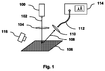
FIG. 5 is a schematic view similar to FIG. 2 showing an arrangement for measuring spectroscopy data of a syringe barrel in a syringe barrel and cap assembly.
FIG. 6 is a schematic view similar to FIG. 2 showing another arrangement for measuring spectroscopy data of a syringe barrel.
FIG. 7 is a schematic view similar to FIG. 2 showing another arrangement for measuring spectroscopy data of a syringe barrel.
FIG. 8 is a schematic view similar to FIG. 2 showing another arrangement for measuring spectroscopy data of a syringe barrel.
FIG. 9 is a schematic view similar to FIG. 2 showing another arrangement for measuring spectroscopy data of a syringe barrel.
FIG. 9 a is a fragmentary detail view similar to FIG. 9 showing another arrangement for measuring spectroscopy data of a syringe barrel.
FIG. 10 is a schematic view similar to FIG. 2 showing another arrangement for measuring spectroscopy data of a syringe barrel.
FIG. 11 is an infrared spectrophotometry spectrum plot of the syringe data of Example 1.
FIG. 12 is a linearized plot of peak height vs. coating time derived from the data shown in FIG. 13 .
FIG. 13 is a linearized plot of peak area vs. coating time derived from the data shown in FIG. 13 .
FIG. 14 is a schematic map of coating thickness versus location for a typical syringe coated as described in the working examples.
FIG. 15 is a view similar to FIG. 5 showing an arrangement for measuring spectroscopy data of a vial as employed in Example 2.
FIG. 16 is a view similar to FIG. 2 showing an auto-injector cartridge.
FIG. 17 is an infrared spectrophotometry spectrum plot of the vial data of Example 2.
FIG. 18 is an infrared spectrophotometry spectrum plot of the syringe data of Example 3.
FIG. 19 is an infrared spectrophotometry spectrum plot of the vial data of Example 4.
FIG. 20 is an infrared spectrophotometry spectrum plot of the vial data of Example 5.
FIG. 21 is a linearized plot of peak area vs. coating time derived from the data shown in FIG. 22 .
FIG. 22 is an infrared spectrophotometry spectrum plot of the vial data of Example 6.
FIG. 23 is a linearized plot of peak area vs. coating time derived from the data shown in FIG. 24 .
FIG. 24 is a linearized plot of peak area vs. coating time of the first set of vial data of Example 7.
FIG. 25 is a linearized plot of peak area vs. coating time of the second set of vial data of Example 7.
FIG. 26 is an optical microscope photograph of a syringe comprising a conventional “land” surface having a diameter of about 1 mm.
FIG. 27 is an optical microscope photograph of a syringe comprising an enhanced “land” surface having a diameter of 2.67 mm.
The following reference characters may be used in the Figures:
TABLE-US-00001 12 Capped pre-assembly 14 Barrel 16 Internal wall 18 Barrel lumen 20 Dispensing portion 22 Front opening 24 Distal opening 26 Dispensing portion lumen 28 Cap 30 (first) Vapor-deposited coating or layer 32 Opening 34 (second) vapor-deposited coating or layer 36 Plunger tip or piston 38 Plunger rod 40 Fluid composition 42 Rib 44 Cylindrical surface 46 Barb 48 Catch 210 Pharmaceutical package 212 Vial 214 Cartridge 216 Impinged infrared light 218 Source (of 216) 220 First surface 222 Collector 224 Collected infrared light 226 Surface 228 Reflected infrared light 230 Axis 232 Coating or deposit of mold lubricant 234 Spectroscopy peak 236 Light guide 238 Impinged position 240 Impinged position 242 Impinged position 244 Mirror 246 Prism 248 pH protective coating 250 Lubricity coating or layer 252 Partially silvered mirror 260 Uncoated syringe, set 1 262 Tie layer and SiO.sub.x coated syringe, set 2 264 Tie layer and SiO.sub.x coated syringe, set 3 268 Vials 1-16 (no pH protection) 270 Vials 17-32 (2.5 sec pH protection) 272 Vials 33-48 (5 sec pH protection) 274 Vials 49-64 (10 sec pH protection) 276 Vials 65-80 (15 sec pH protection) 278 Vials 81-96 (20 sec pH protection) 280 Uncoated syringe 282 Tie layer coated syringe 284 Bilayer (tie and barrier) coated syringe 286 Trilayer (tie, barrier, and protective) coated syringe 290 Uncoated vial 292 Tie layer coated vial 294 Bilayer (tie and barrier) coated vial 296 Trilayer (tie, barrier, and protective) coated vial 300 Tie layer coated vial (2.5 sec) 302 Tie layer coated vial (5 sec) 304 Tie layer coated vial (10 sec) 306 Tie layer coated vial (15 sec) 310 Bilayer coated vial (2.5 sec barrier) 312 Bilayer coated vial (5 sec barrier) 314 Bilayer coated vial (10 sec barrier) 316 Bilayer coated vial (15 sec barrier) 700 Syringe 702 Needle 704 Land DEFINITION SECTION
In the context of the present invention, the following definitions and abbreviations are used:
In the present Figures, the capped pre-assembly 12 is configured as a syringe. The capped pre-assembly 12 can optionally be completed to form a syringe by adding a plunger tip or piston 36 (two interchangeable names for the same structure) and a plunger rod 38 . The internal wall 16 can define at least a portion of the barrel 14 . The plunger tip or piston 36 can be a relatively sliding part of the syringe, with respect to the barrel 14 . The term “syringe,” however, is broadly defined to include cartridges, injection “pens,” and other types of barrels or reservoirs adapted to be assembled with one or more other components to provide a functional syringe. “Syringe” is also broadly defined to include related articles such as auto-injectors, which provide a mechanism for dispensing the contents.
RF is Radio Frequency.
The term “at least” in the context of the present invention means “equal or more” than the integer following the term. The word “comprising” does not exclude other elements or steps, and the indefinite article “a” or “an” does not exclude a plurality unless indicated otherwise. Whenever a parameter range is indicated, it is intended to disclose the parameter values given as limits of the range and all values of the parameter falling within said range.
“First” and “second” or similar references to, for example, coating or layers refer to the minimum number of coating or layers that are present, but do not necessarily represent the order or total number of coating or layers. These terms do not limit the number of coating or layers or the particular processing carried out at the respective stations.
Empirical compositions represented by the formulas SiO.sub.x, SiO.sub.xC.sub.y, and SiO.sub.xC.sub.yH.sub.z are referred to in this specification. The values of x, y, and z used throughout this specification should be understood as ratios or an empirical formula (for example for a coating or layer), rather than as a limit on the number or type of atoms in a molecule. For example, octamethylcyclotetrasiloxane, which has the molecular composition Si.sub.4O.sub.4C.sub.8H.sub.24, can be described by the following empirical formula, arrived at by dividing each of w, x, y, and z in the molecular formula by 4, the largest common factor: SiO.sub.1C.sub.2H.sub.6. The values of x, y, and z are also not limited to integers. For example, (acyclic) octamethyltrisiloxane, molecular composition Si.sub.3O.sub.2C.sub.8H.sub.24, is reducible to SiO.sub.0.67C.sub.2.67H.sub.8. Also, although SiO.sub.xC.sub.yH.sub.z is described as equivalent to SiO.sub.xC.sub.y, it is not necessary to show the presence of hydrogen in any proportion to show the presence of SiO.sub.xC.sub.y.
A “protective coating or layer” according to the present invention is a coating or layer that protects an underlying surface, coating or layer from a fluid composition contacting the coating or layer. The present pH protective coating or layers optionally can have a composition according to the empirical composition Si.sub.wO.sub.xC.sub.yH.sub.z, (or its equivalent SiO.sub.xC.sub.y) as defined herein. It generally has an atomic ratio Si.sub.wO.sub.xC.sub.y (or its equivalent SiO.sub.xC.sub.y) wherein w is 1, x is from about 0.5 to about 2.4, y is from about 0.6 to about 3.
The formula Si.sub.wO.sub.xC.sub.y is an expression of the atomic ratio of Si, O, and C in the “protective coating or layer.” The atomic ratio can be determined by XPS (X-ray photoelectron spectroscopy). Taking into account the H atoms, which are not measured by XPS, the same coating or layer may thus in one aspect have the formula Si.sub.wO.sub.xC.sub.yH.sub.z (or its equivalent SiO.sub.xC.sub.y), for example where w is 1, x is from about 0.5 to about 2.4, y is from about 0.6 to about 3, and z is from about 2 to about 9.
“Slidably” means that the plunger tip or piston, closure, or other movable part is permitted to slide in a syringe barrel, cartridge, or other vessel.
The term “response output” in the context of the present invention is any characteristic or metric that may be measured or calculated from an infrared spectrum and used to indicate the presence and/or thickness of one or more coatings or deposits. For example, the response output may comprise the maximum intensity and/or peak area of the collected infrared light at an infrared spectroscopy peak at one or more wavenumbers or ranges of wavenumbers. Other metrics that are commonly used within Fourier transform infrared spectroscopy (FTIR) may also be relied on. Examples of other metrics include analysis of peak shift changes, slope measurement, curve fitting, first derivative calculations, inflection point determinations, and rhythmic or exponential conversions. Additionally, more than one metric may be used. For example, multiple metrics across a range of wavenumbers may provide a more precise indication of the presence and/or thickness of the coating or deposit.
The term “predetermined parameter” in the context of the present invention is any benchmark or reference standard that can be used to determine whether the desired coating or deposit is present and/or present at an acceptable thickness. For example, the response output may be compared against a benchmark that is derived from a comparison with an uncoated article. For instance, the response output might be compared against an uncoated article and subjected to differential scanning in order to determine whether the portion of the response output attributable to the coating or deposit meets a certain minimum threshold. As another example, the response output may be compared against a reference standard, such as one that may denote a chosen, e.g. minimum acceptable, thickness of the coating or deposit.
Detailed description
An aspect of the invention is a method to detect and measure a vapor-deposited coating or layer such as 30 of SiO.sub.xC.sub.y applied to at least a portion of the internal wall 16 of the barrel 14 of a capped pre-assembly 12 , a syringe barrel 14 , the container of a pharmaceutical package 210 , a vial 212 , a cartridge 214 , or other container. The method is exemplified here with respect to a capped pre-assembly 12 and a vial 212 , but can equally be performed on other types of containers.
Referring to FIGS. 1-10 and 14 , a capped pre-assembly 12 is provided comprising a barrel 14 , optionally a dispensing portion 20 , and a cap 28 . The capped pre-assembly 12 can be a complete article or it can be a portion of a complete article adapted to dispense fluid, such as a syringe, a cartridge, a catheter, a vial, or other article.
The barrel 14 has an internal wall 16 defining a barrel lumen 18 and a front opening 22 through the internal wall 16 . Optionally in any embodiment, the barrel 14 can further include another opening 32 spaced from the dispensing portion 20 and communicating through the internal wall 16 . Such an opening is conventional, for example, in a syringe or cartridge, where a typical example is the back opening 32 of a prefilled syringe barrel, through which the piston or plunger 36 is inserted after the barrel lumen 18 is filled with a suitable pharmaceutical preparation or other fluid material 40 to be dispensed.
The barrel 14 is formed, for example, by molding, although the manner of its formation is not critical and it can also be formed, for example, by machining a solid preform. Preferably, the barrel is molded by injection molding thermoplastic material, although it can also be formed by blow molding or a combined method.
As one preferred example, the barrel 14 can be formed by placing a dispensing portion 20 as described below in an injection mold and injection molding thermoplastic material about the dispensing portion, thus forming the barrel and securing the dispensing portion to the barrel. Alternatively, the dispensing portion (if present) and the barrel can be molded or otherwise formed as a single piece, or can be formed separately and joined in other ways. The barrel of any embodiment can be made of any suitable material. Several barrel materials particularly contemplated are COC (cyclic olefin copolymer), COP (cyclic olefin polymer), PET (polyethylene terephthalate), and polypropylene.
The optional dispensing portion 20 of the capped pre-assembly 12 is provided to serve as an outlet for fluid dispensed from the barrel lumen 18 of a completed article made from the capped pre-assembly 12 . One example of a suitable dispensing portion illustrated in the Figures is a hypodermic needle 20 .
Alternatively, in any embodiment the dispensing portion 20 can instead be a needle-free dispenser. One example of a suitable needle-free dispenser is a blunt or flexible dispensing portion intended to be received in a complementary coupling to transfer fluid material 40 . Such blunt or flexible dispensing portions are well known for use in syringes, intravenous infusion systems, and other systems and equipment to dispense material while avoiding the hazard of working with a sharp needle that may accidentally stick a health professional or other person. Another example of a needle-free dispenser is a fluid jet or spray injection system that injects a free jet or spray of fluid directly through a patient's skin, without the need for an intermediate needle. Any type of dispensing portion 20 , whether a hypodermic needle or any form of needle-free dispenser, is contemplated for use according to any embodiment of the present invention.
The dispensing portion 20 is secured to the barrel 14 and includes a distal opening 24 and a dispensing portion lumen 26 . The front opening 22 communicates with the barrel lumen 18 . The distal opening 24 is located outside the barrel 14 . The dispensing portion lumen 26 communicates between the front opening 22 and the distal opening 24 of the dispensing portion 20 . In the illustrated embodiment, the distal opening 24 is at the sharpened tip of a hypodermic needle 20 .
The cap 28 is secured to the barrel 14 and at least substantially isolates the front opening 22 and the distal opening 24 of the dispensing portion 20 from pressure conditions outside the cap 28 . Optionally in any embodiment, the cap 28 sufficiently isolates portions of the assembly 12 to provide a sufficient bio-barrier to facilitate safe use of the capped pre-assembly 12 for transdermal injections.
The description continues in the full USPTO document.
 Lapsed, fee not paid13 drawings