 Lapsed, fee not paid10 drawings
Software & Apps · US 9,928,545 B1
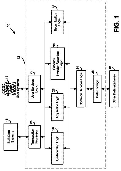
Establishing, modifying, and customizing account-based products
Providing an account-based product.
US 9,928,558 B2 · Assignee: Mitsubishi Electric Corporation · Inventors: Gyota; Tomoaki et al.
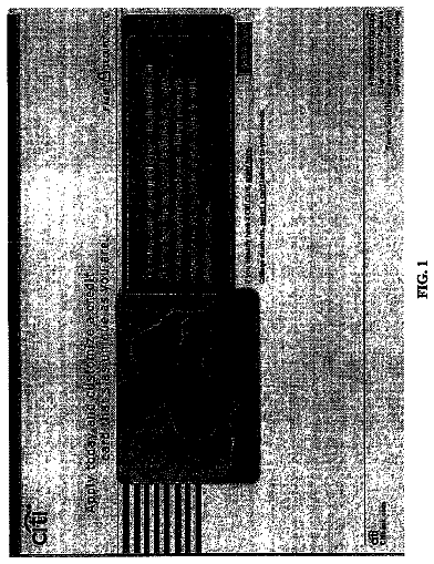
Sheet 1 of 26 from the published document. All sheets in the USPTO PDF
The storage unit prestores element image data presenting an element image contained in a display image in an image data region that is a continuous storage region, and prestores draw command data containing data for creating display data presenting the display image in which the element image is placed in a draw command region that is a continuous storage region. The central processing unit makes reference to a screen management table when a predetermined drawing condition is satisfied to identify and output the draw command identification data corresponding to the satisfied drawing condition. The draw processing unit acquires from the storage unit the draw command data identified with the output draw command identification data, and creates and outputs to the display unit the display data placing the element image based on the acquired draw command data.
Remote controllers for operating home electric appliances and equipment items conventionally utilize a user interface for switching between display/non-display characters and/or graphics printed on a screen. There is an increasing demand for recent remote controllers to display images presenting graphics, characters or the like on a full-dot liquid crystal display and to provide an easy-to-understand interface. On the other hand, the processing load for drawing images is increasing. Execution of a drawing process causes problems such as a delay in the process to control a home electric appliance or equipment item from a remote controller and an increase of memory capacity to store the images. In order to reduce the processing load of the central processing unit, for example, Patent Literature 1 discloses a technique of installing a draw processing unit internally or externally to the cen
1 of 26 drawing sheets so far from the published document, cropped to the drawing. Every sheet is in the USPTO PDF.
What the patent claimed, word for word. All of it is now free to use.
This application is a U.S. national stage application of PCT/JP2013/054274 filed on Feb. 21, 2013, the contents of which are incorporated herein by reference.
The present disclosure relates to a control device and remote controller for displaying images.
Remote controllers for operating home electric appliances and equipment items conventionally utilize a user interface for switching between display/non-display characters and/or graphics printed on a screen. There is an increasing demand for recent remote controllers to display images presenting graphics, characters or the like on a full-dot liquid crystal display and to provide an easy-to-understand interface. On the other hand, the processing load for drawing images is increasing. Execution of a drawing process causes problems such as a delay in the process to control a home electric appliance or equipment item from a remote controller and an increase of memory capacity to store the images. In order to reduce the processing load of the central processing unit, for example, Patent Literature 1 discloses a technique of installing a draw processing unit internally or externally to the central processing unit as dedicated hardware executing the drawing process. CITATION LIST Patent Literature
Patent Literature 1: Unexamined Japanese Patent Application Kokai Publication No. 2010-175638. SUMMARY OF INVENTION Technical Problem
However, the technique described in the Patent Literature 1 with the use of a central processing unit having a draw processing unit internally installed requires the program for the central processing unit to be updated as well the screen design of a display image is changed. Therefore, writing errors and/or version errors may occur while the program is updated.
The present disclosure is made under the above circumstance and an objective of the disclosure is to provide a control device and remote controller making it possible to change the screen design of a display image without changing the existing central processing unit and the existing programs of the central processing unit. Solution to Problem
In order to achieve the above objective, the control device according to the present disclosure comprises:
a storage unit configured to prestore element image data presenting an element image contained in a display image that is an image to be displayed on a display unit in an image data region that is a continuous storage region, and prestore draw command data containing data for creating display data presenting the display image in which the element image is placed in a draw command region that is a continuous storage region;
a central processing unit configured to prestore a screen management table associating drawing condition data presenting a predetermined drawing condition and draw command identification data presenting an address within the storage unit where the draw command data are stored, make reference to the screen management table when the drawing condition is satisfied to identify the draw command identification data associated with the drawing condition data presenting the satisfied drawing condition, and output the identified draw command identification data; and
a draw processing unit configured to acquire from the storage unit the draw command data stored at the address presented by the draw command identification data output from the central processing unit, create the display data based on the acquired draw command data, and output the created display data to the display unit. Advantageous Effects of Invention
According to the present disclosure, element image data and draw command data are each collectively placed in different storage regions of a storage unit. Therefore, even if some contents of the element image data are changed for changing the screen design of a display image, the address where the draw command data are stored is unchanged. Thus, when the screen design of a display image is changed, since there is no need of changing draw command identification data output by the central processing unit, there is no need of changing the details of the processing executed by the central processing unit. Consequently, the screen design of a display image can be changed without changing the existing central processing unit and the existing programs of the central processing unit.
FIG. 1 is a diagram showing the configuration of the remote controller according to Embodiment 1;
FIG. 2 is an illustration showing exemplary data placement within the storage unit according to Embodiment 1;
FIG. 3 is an illustration showing an example of the draw command data according to Embodiment 1;
FIG. 4 is an illustration showing exemplary relationship among the regions used by the draw processing unit for creating display data;
FIG. 5 is an illustration showing an example of the screen management table according to Embodiment 1;
FIG. 6 is an illustration showing an example of the conversion procedure executed by the drawer;
FIG. 7 is a chart showing an exemplary flow of the processing executed by the remote controller according to Embodiment 1;
FIG. 8 is a flowchart showing the details of the draw command execution procedure shown in FIG. 7 ;
FIG. 9 is a flowchart showing the details of the element drawing procedure shown in FIG. 8 ;
FIG. 10 is an illustration showing an exemplary case in which the screen contents of a display image displayed under the same drawing condition are changed depending on the destination;
FIG. 11 is a flowchart showing exemplary modified details of the draw command execution procedure shown in FIG. 7 ;
FIG. 12 is a flowchart showing the details of the element drawing procedure shown in FIG. 11 ;
FIG. 13 is a diagram showing the configuration of the remote controller according to Modified Embodiment 2;
FIG. 14 is an illustration showing an example of the draw command data according to Modified Embodiment 2;
FIG. 15 is an illustration showing an example of the screen management table according to Modified Embodiment 2;
FIG. 16 is a chart showing an exemplary flow of the processing executed by the remote controller according to Modified Embodiment 2;
FIG. 17 is a diagram showing the configuration of the remote controller according to Embodiment 2;
FIG. 18 is an illustration showing an example of the draw command data according to Embodiment 2;
FIG. 19 is an illustration showing an example of the interrupt response table according to Embodiment 2;
FIG. 20A is a chart showing an exemplary flow of the processing executed by the remote controller according to Embodiment 2;
FIG. 20B is a chart showing an exemplary flow of the processing executed by the remote controller according to Embodiment 2;
FIG. 21 is a flowchart showing the details of the draw command execution procedure shown in FIG. 20 ;
FIG. 22 is a flowchart showing the details of the element address extraction procedure shown in FIG. 20 ;
FIG. 23 is an illustration showing another exemplary case in which the screen contents of a display image displayed under the same drawing condition are changed depending on the destination;
FIG. 24 is an illustration showing exemplary data placement within the storage unit according to Modified Embodiments 4 and 5; and
FIG. 25 is a diagram showing the configuration of the remote controller according to Modified Embodiment 6.
Embodiments of the present disclosure will be described hereafter with reference to the drawings. The same elements are referred to by the same reference numbers throughout the drawings. Duplicate explanation regarding the same element will be omitted. Embodiment 1
The remote controller according to Embodiment 1 of the present disclosure is a device for the user to operate an air conditioner. Here, the air conditioner is an example among various devices and the object to operate using the remote controller can be a home electric appliance or equipment item such as a lighting apparatus and security system.
A remote controller 1 according to this embodiment comprises, as shown in FIG. 1 , an operator 2 and a control device 3 .
The operator 2 includes a portion operated by the user and outputs operation signals according to the operation. The operator 2 according to this embodiment comprises multiple buttons the user presses for operation and outputs operation signals according to the pressed button. Moreover, the operator 2 can be a lever, touch panel, or the like.
The control device 3 is a device in charge of total control of the remote controller 1 , and comprises, as shown in FIG. 1 , a display unit 4 , a storage unit 5 , a central processing unit 6 , and a draw processing unit 7 .
The display unit 4 is a device displaying a display image on a screen, and comprises, as shown in FIG. 1 , a display 8 , a VRAM (video random access memory) 9 , a VRAM data acquirer 10 , and a display controller 11 .
The display 8 is, for example, a 32-gradation gray scale full-dot type liquid crystal device and displays an image of a given number of pixels on a screen of a given size. Here, the display 8 can be one capable of color display. The VRAM 9 is a RAM retaining VRAM data (display data). The VRAM data acquirer 10 is an interface acquiring VRAM data output from the draw processing unit 7 and stores the acquired VRAM data in the VRAM 9 . The display controller 11 periodically acquires VRAM data stored in the VRAM 9 and displays a display image presented by the acquired VRAM data on the screen of the display 8 .
The storage unit 5 is a device storing various data and comprises, for example, an EEPROM (electrically erasable programmable read only memory), serial flash ROM (read only memory), parallel flash ROM, or the like.
The storage unit 5 stores element image data 12 and draw command data 13 separately at predetermined addresses as shown in FIG. 1 .
Here, the element image data 12 are stored in an image data region successively without spaces as shown in FIG. 2 . Moreover, the draw command data 13 are stored in a draw command region successively without spaces. The image data region and draw command region are each a given range of block of storage region of the storage unit 5 that has consecutive addresses starting with a given address.
The element image data 12 contain an image (an element image) presenting an element such as a character, symbol, and graphic included in a display image to be displayed on the entire screen or a partial screen (window) of the display 8 .
For example, when the air conditioner is in air cooling operation, the element images are images presenting the characters “C,” “O,” “O,” and “L” indicating the air cooling operation, images presenting the digits “0” to “9” presenting a target temperature and “° C.,” and an image presenting the air rate by a graphic. Moreover, a single element image can comprise multiple characters such as “COOL” and an element image can contain a background image.
The draw command data 13 contain data necessary for creating a command (a draw command) to be executed for creating display data presenting a display image. The draw command data 13 contain, as shown in FIG. 3 , a window region set command 14 , an element draw command 15 , and an end command 16 presenting the end of the draw command data 13 . The data 14 to 16 contained in the draw command data 13 each have a fixed length and therefore the draw command data 13 also have a fixed length.
The window region set command 14 is a command for setting a window region within a virtual region that is the largest region the draw processing unit 7 can handle. The window region set command 14 contains, as shown in the same figure, a header 17 indicating that the elements of the window region set command 14 follow, and virtual region coordinate values 18 to 21 presenting a position within the virtual region at which a rectangular window region is set.
The virtual region coordinate values 18 to 21 contained in the first (leftmost in the same figure) window region set command 14 shown in the same figure present a rectangular region (X 0 , X 1 , Y 0 , Y 1 ). Here, the rectangular region (X 0 , X 1 , Y 0 , Y 1 ) presents a rectangular region of which the minimum and maximum virtual region coordinate values in the direction X are X 0 and X 1 , respectively, and the minimum and maximum virtual region coordinate values in the direction Y are Y 0 and Y 1 , respectively.
FIG. 4 shows an exemplary window region 23 set within a virtual region 22 based on the first window region set command 14 . The virtual region coordinate values (X, Y) of this embodiment are presented, as shown in the same figure, by a virtual region coordinate system having the origin at the top right of the same figure and of which the direction X is horizontal and the direction Y is vertical.
The element draw command 15 is a command for placing in the window region 23 an element region 24 that is a rectangular region circumscribing an element image. Moreover, the element region 24 is not necessarily rectangular and can be circular or elliptical as appropriate. The element draw command 15 contains, as shown in FIG. 3 , a header 25 , an element type 26 , relative coordinate values 27 to 30 , and an element address 31 .
The header 25 indicates that the elements of the element draw command 15 follow. The element type 26 presents the type of image compression used for the element image data 12 such as the GIF and JPEG. The relative coordinate values 27 to 30 present a position within the window region 23 at which the element region 24 is placed. The element address 31 presents an address within the storage unit 5 where the element image data 12 are stored.
Here, the relative coordinate values 27 to 30 exemplify data for identifying a position at which an element image is placed (element placement data). The element address 31 exemplifies data for identifying the element image data 12 (element identification data).
The relative coordinate values 27 to 30 contained in the element draw command 15 following the first window region set command 14 shown in the same figure present a rectangular region (RX 0 , RX 1 , RY 0 , RY 1 ) of which the minimum and maximum relative coordinate values in the direction X are RX 0 and RX 1 , respectively, and the minimum and maximum relative coordinate values in the direction Y are RY 0 and RY 1 , respectively.
The relative coordinate values are the coordinate values presenting a position within the window region set by the window region set command 14 . The relative coordinate values (RX, RY) of this embodiment are presented, as shown in FIG. 4 , by a relative coordinate system having the origin of relative coordinates at the virtual region coordinates (X 0 , Y 0 ) at the top right corner of the window region 23 and of which the direction X is horizontal and the direction Y is vertical. The element region 24 in the same figure exemplifies the element region 24 placed according to the relative coordinate values 27 to 30 contained in the element draw command 15 following the first window region set command 14 .
Moreover, a VRAM region (display region) 32 is a region corresponding to the screen of the display 8 and set, for example, at the center of the virtual region 22 as shown in the same figure. Therefore, in the same figure, the image in a portion where the window region 23 and VRAM region 32 overlap is a display image. In other words, an element image placed in a portion where the window region 23 and VRAM region 32 overlap is displayed on the screen of the display 8 . Furthermore, an element image placed in a portion of the window region 23 that protrudes above or below the VRAM region 32 is not displayed on the screen of the display 8 and will be displayed on the screen of the display 8 as the window region 23 is scrolled.
Returning to FIG. 1 , the central processing unit (microcomputer) 6 is a device in charge of total control of the remote controller 1 , and comprises a controller 33 , a RAM (random access memory) 34 , a ROM 35 , a communicator 36 , and an input port 37 .
Interpreting software programs (“programs,” hereafter) read from the ROM 35 , the controller 33 executes arithmetic operations and controls peripheral functions such as the RAM 34 , ROM 35 , communicator 36 , and input port 37 according to the interpreted contents.
The RAM 34 is a volatile memory used as the work area of the controller 33 .
The ROM 35 is a nonvolatile memory storing programs executed by the controller 33 and prestores a control application 40 and a screen management table 41 .
The control application 40 is a program for executing the total control (main control) of the remote controller 1 and controlling/operating controlled devices.
The screen management table 41 stores drawing conditions for updating screen contents and the screen contents to display when the drawing conditions are satisfied.
FIG. 5 shows an example of the screen management table 41 . The screen management table 41 associates, for each screen number, a draw command address and screen numbers corresponding to operation types. The screen number is a number preassigned to an individual screen for uniquely identifying the type of a screen such as an initial screen and operation input screen. The draw command address is an address within the storage unit 5 where the draw command data 13 for displaying the associated screen are stored. The operation type is the type of an operation conducted by the user on the operator 2 . The operation type in this embodiment presents which button is pressed among those identified by buttons 0 to N. The screen number corresponding to the operation type presents the screen number of a screen to display next in accordance with the type of an operation conducted while the screen of the associated screen number (the screen number shown in the leftmost column in FIG. 5 ) is displayed. Here, the above-mentioned drawing condition corresponds to the displayed screen number and operation type and the above-mentioned screen content corresponds to the draw command address. Moreover, the draw command address exemplifies the draw command identification data for identifying the draw command data 13 .
Returning to FIG. 1 , the communicator 36 is a communication interface for outputting a host command from the central processing unit 6 to the draw processing unit 7 and reading/writing the register contents of the draw processing unit 7 . Specific communication interface systems include clock synchronization serial, asynchronous serial communication, and universal bus systems.
The input port 37 detects operation signals from the operator 2 , interrupt signals from the draw processing unit 7 , and the like.
The draw processing unit 7 comprises, as shown in FIG. 1 , a register 45 , a host interface 46 , a storage interface 47 , a command interpreter 48 , and a drawer 49 .
The register 45 stores information used by the draw processing unit 7 in the drawing procedure. As shown in the same figure, the register 45 has a drawing start request register 61 , a draw command address register 62 , a window region register 63 , a scrolling amount register 64 , an element type register 65 , an element region register 66 , an element address register 67 , and an interrupt register 68 .
The drawing start request register 61 is a register for the central processing unit 6 to order the draw processing unit 7 to start the drawing procedure. The draw command address register 62 is a register for setting an address within the storage unit 5 where the draw command data 13 to process are stored. The window region register 63 is a register for setting a window region indicated in the draw command to process. The scrolling amount register 64 is a register for setting the shifting amount s (scrolling amounts) of the window region in the directions X and Y. The element type register 65 is a register for setting the type of an element image to draw. The element region register 66 is a register for setting the drawing destination coordinates (relative coordinates with respect to the window region) of an element image to draw. The element address register 67 is a register for setting an address within the storage unit 5 where the element image to draw is stored. The interrupt register 68 is a register for setting a drawing end flag indicating the end of drawing.
The host interface 46 reads/writes the content of the register 45 at a given location according to a host command received from the central processing unit 6 .
Furthermore, the host interface 46 outputs an interrupt signal to the input port 37 of the central processing unit 6 when the drawing end flag in the interrupt register 68 is set.
The storage interface 47 is an interface acquiring from the storage unit 5 the draw command data 13 or element image data 12 in a given data size unit (for example, 1 byte).
The command interpreter 48 monitors the drawing start request register 61 . As a flag ordering start of drawing (a drawing start flag) is set in the drawing start request register 61 , the command interpreter 48 acquires the draw command data 13 from the storage unit 5 via the storage interface 47 . In detail, the command interpreter 48 acquires a succession of draw command data 13 stored in the storage unit 5 from the address set in the draw command address register 62 .
Then, the command interpreter 48 interprets the draw command data 13 and stores the data contained in the draw command in the corresponding registers 63 and 65 to 67 . In doing so, the command interpreter 48 gives an element drawing request notice to the drawer 49 each time an element draw command of the draw command data 13 is read, and pauses the reading of the draw command data 13 . The command interpreter 48 resumes the reading of the draw command data 13 after receiving an element drawing end notice from the drawer 49 . Here, the element drawing request notice is a notice indicating a request to start drawing an element image. The element drawing end notice is a notice indicating the end of drawing an element image.
Receiving the above-mentioned element drawing request notice, the drawer 49 executes the element image drawing procedure. In detail, the drawer 49 acquires the element image data 12 from the storage unit 5 via the storage interface 47 based on the address set in the element address register 67 . The drawer 49 executes expansion according to the image type presented by the image type data stored in the element type register 65 to create drawing data.
Furthermore, the drawer 49 makes reference to the window region register 63 , scrolling amount register 64 , and element region register 66 , and calculates the coordinate positions on the virtual region at which the individual pixels of the element image are placed according to the referred registers 63 , 64 , and 66 . The drawer 49 creates drawing data of the element image contained in the VRAM region 32 , that is the data presenting the coordinate positions of the individual pixels. More specifically, the drawing data are data presenting the pixel values of the individual pixels and in the case of a monochrome image, present each pixel by one bit (white, black).
The drawer 49 converts the created drawing data to VRAM data 55 in a format in compliance with the display unit 4 . The drawer 49 writes the converted VRAM data 55 via the VRAM data acquirer 10 at the positions on the VRAM 9 corresponding to the coordinate positions presented by the data created along with the drawing data. In this conversion procedure, for example, as shown in FIG. 6 , drawing data 53 for three monochrome pixels are converted to 16-bit VRAM data 55 .
The configuration of the remote controller 1 according to Embodiment 1 of the present disclosure is described above. The procedures executed by the operating remote controller 1 according to this embodiment will be described hereafter with reference to the drawings.
As shown in FIG. 7 , the central processing unit 6 runs the control application 40 to execute the main control procedure (Step S 101 ).
If the user operates the operator 2 during execution of the main control procedure (Step S 101 ), an operation signal is entered in the input port 37 . As a result, the central processing unit 6 detects the operation input of the user (Step S 102 ) and pauses the main control procedure.
The central processing unit 6 makes reference to the screen management table 41 (Step S 103 ) and identifies the draw command address of the next display screen according to the satisfied drawing condition based on the screen number of the screen displayed on the display unit 4 and the operation type indicated by the acquired operation signal (Step S 104 ).
For example, it is assumed that the operation type indicated by the operation signal acquired by the central processing unit 6 is a “button 0” and the screen number of the screen displayed at the time is “0.” With reference to the screen management table 41 shown in FIG. 5 , the screen number of the display screen to draw next is “2.” The central processing unit 6 identifies the draw command address “CCCCC” associated with the screen number “2” as the draw command address of the next display screen.
Then, the central processing unit 6 outputs a host command for setting the identified draw command address in the draw command address register 62 to the draw processing unit 7 via the communicator 36 (Step S 105 ). At this point, the central processing unit 6 can further set a fixed value, for example “0,” in the scrolling amount register 64 .
The host interface 46 of the draw processing unit 7 sets the draw command address corresponding to the entered host command in the draw command address register 62 as shown in FIG. 7 (Step S 106 ).
Then, the central processing unit 6 outputs a host command for writing a drawing start flag in the drawing start request register 61 (a drawing start request) to the draw processing unit 7 (Step S 107 ). Subsequently, the controller 33 resumes the paused main control procedure (Step S 108 ).
In response to a drawing start request being entered, the host interface 46 of the draw processing unit 7 sets a drawing start flag in the drawing start request register 61 (Step S 109 ).
The command interpreter 48 of the draw processing unit 7 monitoring the drawing start request register 61 detects the drawing start flag being set and executes the draw command execution procedure (Step S 110 ).
In the draw command execution procedure (S 110 ) described in detail later, the draw processing unit 7 acquires the draw command data 13 from the storage unit 5 at the address indicated by the draw command address register 62 as shown in the same figure (Step S 131 ). At this point, the draw processing unit 7 increases the content of the draw command address register 62 by +1 each time one byte of the draw command data 13 is acquired. As a result, the command interpreter 48 can acquire the draw command data 13 one byte at a time with reference to the draw command address register 62 . The draw processing unit 7 repeats the process to set a window region or the process to draw an element image in accordance with the contents of the draw command data 13 acquired in sequence until the end command 16 is acquired.
When the acquired draw command data 13 are of an element draw command 15 , the command interpreter 48 orders the drawer 49 to start the element image drawing procedure after acquisition of one element draw command 15 is completed. The drawer 49 acquires the element image data 12 from the address indicated by the element address register 67 as shown in the same figure (Step S 141 ). At this point, the drawer 49 increases the content of the element address register 67 by +1 each time one byte of the element image data 12 is acquired and acquires the element image data 12 one byte at a time with reference to the element address register 67 . The drawer 49 expands the acquired element image data 12 to create drawing data 53 . The drawer 49 creates data presenting the coordinate positions of the individual pixels contained in the element image presented by the created drawing data 53 .
The drawer 49 converts the drawing data 53 in data format to VRAM data 55 and outputs the obtained, converted VRAM data 55 to the display unit 4 (Step S 146 shown in FIG. 9 ). After processing all pixels contained in the element image data 12 in process, the drawer 49 gives an element drawing end notice to the command interpreter 48 . In response to the element drawing end notice, the command interpreter 48 resumes acquisition of the draw command data 13 .
After acquiring an end command 16 , the command interpreter 48 sets a drawing end flag indicating that the drawing process is over in the interrupt register 68 . As a result, the host interface 46 detects the set drawing end flag and outputs an interrupt signal to the central processing unit 6 (Step S 139 ).
Detecting the interrupt signal (Step S 111 ), the central processing unit 6 pauses the main control procedure, and outputs a host command for clearing the interrupt register 68 (a drawing end flag clearing order) to the draw processing unit 7 via the communicator 36 (Step S 112 ). Then, the controller 33 resumes the main control procedure (Step S 113 ).
Acquiring an end interrupt clearing order from the central processing unit 6 , the host interface 46 of the draw processing unit 7 clears the interrupt register 68 and ceases the interrupt signal (Step S 114 ).
As apparent from the above explanation, the procedure executed by the central processing unit 6 to display a display image on the display 8 comprises the processing from detection of an operation (Step S 102 ) to output of a drawing start request (Step S 107 ), acquisition of an interrupt signal (Step S 111 ), and interrupt clearing order (Step S 112 ). This process is significantly smaller than the process to create draw command data as in the prior art. Therefore, the processing load of the central processing unit 6 to display a display image on the display 8 can significantly be reduced.
The draw command execution procedure (Step S 110 ) executed by the draw processing unit 7 will be described in detail below.
The draw command execution procedure (Step S 110 ) starts when the command interpreter 48 detects a drawing start flag in the drawing start request register 61 . The command interpreter 48 having detected a drawing start flag acquires the draw command data 13 placed at the address stored in the draw command address register 62 from the storage unit 5 via the storage interface 47 (Step S 131 shown in FIG. 7 ).
In detail, the command interpreter 48 increases the content of the draw command address register 62 by +1 after acquiring one byte of the draw command data 13 from the storage unit 5 via the storage interface 47 . Repeating this operation, the command interpreter 48 acquires the draw command data 13 one byte at a time. For the purpose of simplicity, description regarding the repeated acquisition of draw command data is omitted in the following explanation. However, the following processing can be executed as appropriate while the draw command data 13 are acquired one byte at a time.
As shown in FIG. 8 , the command interpreter 48 interprets the headers 17 and 25 contained in the draw command data 13 and determines whether the command type is a window region set command 14 , an element draw command 15 , or an end command 16 (Step S 132 ).
If the draw command type is a window region set command 14 in the Step S 132 , the command interpreter 48 sets the window region contained in the window region set command in the window region register 63 (Step S 133 ). Subsequently, the command interpreter 48 returns to the Step S 132 .
For example, it is assumed that the draw command data 13 contain the contents shown in FIG. 3 and the command interpreter 48 identifies a window region set command 14 based on the header 17 in the Step S 132 . In such a case, the command interpreter 48 sets the window region (X 0 , X 1 , Y 0 , Y 1 ) in the window region register 63 in the Step S 133 .
If the draw command type is an element draw command 15 in Step S 132 , the command interpreter 48 sets the element type 26 , element regions 27 to 30 , and element address 31 contained in the element draw command 15 in the element type register 65 , element region register 66 , and element address register 67 , respectively (Steps S 134 to S 136 ). As a result, after acquisition of one element draw command 15 is completed, the command interpreter 48 outputs an element drawing request notice to the drawer 49 .
For example, it is assumed that the draw command data 13 contain the contents shown in FIG. 3 and the command interpreter 48 identifies an element draw command 15 based on the header 25 in the Step S 132 . In such a case, the command interpreter 48 sets the element region (RX 0 , RX 1 , RY 0 , RY 1 ) in the element region register 66 in the Step S 135 .
As an element drawing request notice is entered, the drawer 49 starts the element image drawing procedure (Step S 137 ). The element drawing procedure (Step S 137 ) will be described with reference to FIG. 9 .
As shown in the same figure, the drawer 49 first acquires the element image data 12 at the address set in the element address register 67 from the storage unit 5 via the storage interface 47 (Step S 141 ). At this point, the drawer 49 increases the content of the element address register 67 by +1 each time one byte of the element image data 12 is acquired.
The drawer 49 expands the acquired element image data 12 by a method corresponding to the element type 26 set in the element type register 65 to create element image drawing data 53 (Step S 142 ).
The drawer 49 calculates an element region 24 presented by virtual region coordinate values on the virtual region 22 based on the data stored in the window region register 63 , scrolling amount register 64 , and element region register 66 (Step S 143 ).
For example, when the window region is a rectangular region (X 0 , X 1 , Y 0 , Y 1 ) in virtual region coordinate value, the scrolling amount is SX in the direction X and SY in the direction Y, and the element region 24 is a rectangular region (RX 0 , RX 1 , RY 0 , RY 1 ) in relative coordinate value, the calculated position of the element region 24 presented by the virtual region coordinate values is a rectangular region (X 0 +RX 0 +SX, X 0 +RX 1 +SX, Y 0 +RY 0 +SY, Y 0 +RY 1 +SY) in virtual region coordinate value. FIG. 4 shows the element region 24 when both the SX and SY are 0.
When the element region 24 corresponding to the element draw command 15 to process has a portion (region) overlapped with the RAM region 32 (Step S 144 ; Yes), the drawer 49 creates drawing data 53 presenting the element image within the overlapped region. The drawer 49 converts the drawing data to VRAM data 55 as described above (Step S 145 ). The drawer 49 outputs the obtained, converted VRAM data 55 to the display control unit 4 (Step S 146 ).
After output of all of the VRAM data 55 presenting the element image within the region overlapped with the VRAM region 32 is completed (Step S 146 ) or when the element region 24 has no region overlapped with the VRAM region 32 (Step S 144 ; No), the drawer 49 outputs an element drawing end notice to the command interpreter 348 (Step S 147 ). Then, the drawer 49 ends the element drawing procedure (Step S 137 ). Receiving the element drawing end notice, the command interpreter 348 returns to the Step S 132 .
As the element drawing procedure (Step S 137 ) is executed as described above, the VRAM data 55 presenting an element image and the display position of the element image on the screen of the display 8 are created and output to the display unit 4 .
Here, although not shown, the VRAM data acquirer 10 of the display unit 4 acquires the VRAM data 55 presenting an element image. Then, the VRAM data acquirer 10 stores the VRAM data 55 in the VRAM 9 so that the element image is placed at the position on the screen of the display 8 corresponding to the position of the element region 24 within the VRAM region 32 . Consequently, the element image is placed at a proper position and displayed on the display 8 by the display controller 11 .
From then on, the window region set command 14 and element draw command 15 are similarly processed, whereby a screen displaying multiple element images in one window region and/or displaying an element image in another window region is displayed on the display 8 .
Returning to FIG. 8 , if the draw command type is an end command 16 in the Step S 132 , the command interpreter 48 sets a drawing end flag in the interrupt register 68 (Step S 138 ).
Detecting a drawing end flag being set, for example, by monitoring the interrupt register 68 , the host interface 46 outputs an interrupt signal to the central processing unit 6 (Step S 139 ). Then, the draw processing unit 7 ends the draw command execution procedure (Step S 110 ).
It is a general practice to use a common remote controller for air conditioners at multiple destinations in some cases. In such cases, the screen contents of a display image displayed when a specific drawing condition is satisfied may be changed depending on the destination. For example, the screen contents are changed for conforming to the culture and/or display language of the destination.
FIG. 10 is an illustration showing an exemplary case in which the screen contents of a display image displayed under the same drawing condition are changed depending on the destination. The figure shows a case in which the screen contents of a display image at a destination A are changed to those at a destination B.
In detail, the element image presenting the operation mode is changed from “HEAT” at the destination A to “an icon+HEAT” at the destination B and additionally the position and size of the element image are changed. With this change, the data size of the element image data 12 presenting the operation mode is generally increased. Therefore, the storing locations of the element image data 12 following the element image data 12 presenting the operation mode are changed. If the change of the storing location of the element image data 12 presenting the operation mode affects the storing location of the element image data 12 presenting, for example, a number, the element address 31 contained in the draw command data 13 has to be changed. Furthermore, since the size and display position of the element image presenting the operation mode are changed, the relative coordinate values 27 to 30 (“RX 0 , RX 1 , RY 0 , RY 1 ” in FIG. 2 ) of the element draw command 15 are changed.
As for the digits and “° C.” of the temperature display, only the display position is changed. Then, the relative coordinate values 27 to 30 of the draw command data 13 are changed.
As for the digits and “%” of the humidity display, the element image and the size and display position thereof are changed like the operation mode. Then, the element address 31 and relative coordinate values 27 to 30 of the draw command data 13 are changed.
As described above, along with the change in screen contents shown in FIG. 10 , the contents of the element image data 12 stored in the storage unit 5 , the location (address) where the element image data 12 are stored, the relative coordinate values 27 to 30 contained in the draw command data 13 , and the element address 31 contained in the draw command data 13 are changed. At this point, the draw command data 13 are changed only in values contained therein; the data size thereof does not change. Therefore, the draw command identification data output by the central processing unit 6 are the same before and after the screen contents are changed.
Embodiment 1 of the present disclosure is described above.
The description continues in the full USPTO document.
About 7,061 words. The USPTO PDF has it with every drawing.
Fees are due 3.5, 7.5 and 11.5 years after grant. This patent expired on March 27, 2026, so the fee marked "not paid" was the one that went unpaid.
CONTROL DEVICE AND REMOTE CONTROLLER
Filed Feb 2013 · published Dec 2015Control device and remote controller
Filed Feb 2013 · granted Mar 2018Earlier publications, parents and continuations. None of them can still be enforced, or this patent would not be listed.
Prior art cited by the examiner or applicant. Useful when you check your own idea for novelty.
Everything on this page comes from the documents linked above.