 Lapsed, fee not paid5 drawings
Industrial Equipment · US 9,919,858 B2
Buffering member
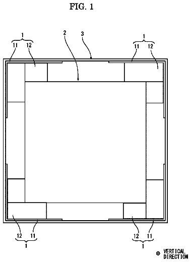
A buffering member is interposed between an outer corner of a packaged article and an inner corner of a packaging box.
US 9,919,861 B2 · Assignee: WestRock MWV, LLC · Inventors: Bolognia; David B. et al.
Sheet 1 of 14 from the published document. All sheets in the USPTO PDF
A housing module ( 601 ) for use with a smart package ( 110 ) has a main body suitable for having an electronic device ( 605 ) affixed thereto. The main body includes one or more retention wings ( 603 a, 603 b ) extending from the main body. The one or more retention wings are sized and configured for co-operation with a slot ( 88 a, 88 b ) associated with the smart package ( 110 ) such that the housing module ( 601 ) is retainable substantially within the smart package ( 110 ). The one or more retention wings ( 603 a, 603 a ) are shaped, sized and configured to co-operate with an end-stop of the slot ( 88 a, 88 b ) for locating the housing module ( 601 ) within the smart package ( 110 ).
In the field of smart packaging for dispensing articles, specifically, but not exclusively to the field of smart packaging for use in healthcare applications, it is known to provide packaging systems, wherein electronic modules are provided. Data relating to the use of the package and the dispensing of medication is collected and analysed by the electronics module in order to track and monitor the administration of medication by patients. It is also known to provide packaging systems that are configured to issue reminder signals to patients and that are configured to provide an indication of a patient's compliance with their treatment plan. Such smart packaging has many benefits which may include: improving the effectiveness of medical treatment; mitigating against incorrect dosages being taken; and/or reducing the labour expended by medical professionals that might otherwise be involved
8 of 14 drawing sheets so far from the published document, cropped to the drawing. Every sheet is in the USPTO PDF.
What the patent claimed, word for word. All of it is now free to use.
The present invention relates generally to smart packages for dispensing articles and to lockable packages such as child-resistant, senior-friendly packages for healthcare type applications. More specifically, but not exclusively, the invention relates to sleeve-and-drawer style packages having an internal slidable lockable receptacle, that is releasably lockable within an outer sleeve; and to an auxiliary device for use in collecting data relating to the dispensing of articles held by the internal lockable receptacle.
Aspects of the invention relate to a package, to an outer sleeve, to a lockable receptacle, to housing modules, to an outer sleeve blank and to a lockable receptacle blank.
In the field of smart packaging for dispensing articles, specifically, but not exclusively to the field of smart packaging for use in healthcare applications, it is known to provide packaging systems, wherein electronic modules are provided. Data relating to the use of the package and the dispensing of medication is collected and analysed by the electronics module in order to track and monitor the administration of medication by patients. It is also known to provide packaging systems that are configured to issue reminder signals to patients and that are configured to provide an indication of a patient's compliance with their treatment plan. Such smart packaging has many benefits which may include: improving the effectiveness of medical treatment; mitigating against incorrect dosages being taken; and/or reducing the labour expended by medical professionals that might otherwise be involved in tracking and monitoring a patient's treatment.
EP1,495,746 B1 discloses some known smart packages comprising a dispenser, a blister card and means for detecting or determining when access has been gained to the blister card within the package. One dispenser disclosed has a curved body to facilitate a friction fit of a blister card therein; an open end; and a slot provided to enable a user's finger to contact and easily slide the blister card out of the open end of the dispenser. It is disclosed that the means for detecting or determining when access has been gained to the blister card comprises a detector, based upon optical, magnetic or mechanical principles, that is able to detect a feature of the blister card when the blister card mates with the detector. The detector is coupled to electronics for storing data and for issuing reminder signals to a patient in order to track and improve patient compliance.
Whereas it may improve patient compliance with a course of medication if the patient is able to readily gain access to the blister card containing their medication, it is extremely undesirable for a non-authorised user of the package, for example a child to be able to readily gain access to pharmaceutical products.
There is therefore a requirement for a smart packaging system that is sufficiently child-resistant whilst at the same time being sufficiently senior friendly so as to avoid discouraging a patient from accessing their medication. Further considerations for this type of packaging are the need for the packaging to be able to withstand repeated use, be more economical to produce and preferably be made of recyclable and/or sustainable materials.
Child resistant, senior friendly sleeve and drawer style packages are known, for example from U.S. Pat. No. 6,047,829, wherein a two-piece paperboard package is disclosed that houses a unit dose product on an internal slide card within an outer paperboard shell. The package has an internal lock that prevents the slide card from being pulled out without first triggering a lock release mechanism. The package is thereby child resistant and senior friendly.
The present disclosure provides improvements in the field of smart packaging by providing a generally paperboard, sleeve and drawer style child resistant, senior friendly smart packaging system comprising means for detecting or determining when the contents thereof have been accessed and/or for providing other data collation, use tracking and/or reminder signalling to improve patient compliance.
Whereas the invention finds particular beneficial application in the field of healthcare packaging where sleeve-and-drawer packages contain unit dose packages for pharmaceutical tablets, the invention of the present disclosure is not limited to that application and advantageous features components and combinations thereof disclosed herein may be employed in other packaging and dispensing applications. For example, packaging systems of the present disclosure may be utilised in automated inventory and other product tracking applications where the dispensing and/or use of products, such as, but not limited to: small tools, medical devices, small high-value items such as consumer electronics and other consumable items, is beneficially monitored and tracked.
According to a first aspect of the present invention for which protection is sought, there is provided a housing module for use with a smart package, the housing module having a main body suitable for having an electronic device affixed thereto, the main body comprising one or more retention wings extending from the main body, the one or more retention wings each being sized and configured for co-operation with a slot comprised within the smart package such that the housing module is retainable substantially within the smart package. The one or more retention wings are shaped, sized and configured to co-operate with an end-stop of the slot for locating the housing module within the smart package. Beneficially, therefore the housing module is affixable within the smart package without the need for adhesive or other auxiliary affixing mechanisms (screws, fasteners and the like). This permits the housing module to be easily re-used if required.
Optionally, the main body has first and second side walls connected together by a top wall and comprises two retention wings, each retention wing being substantially planar in form and extending from a lower edge of the first and second side walls respectively. The side walls provide additional protection for the electronics device when affixed thereto and also provide a further means for interlocking the housing module to a smart package.
Optionally, the two retention wings are each shaped, sized and configured to co-operate with an end-stop of the slot within the smart package by having a recessed or hook-shaped portion.
Optionally, each of the two retention wings has a length that is less than the length of the first or second side wall from which the retention wing extends.
Optionally, the housing module further comprises a front wall and one or more lifting teeth having a ramped upper surface for guiding a registration mechanism of the smart package toward a registration slot, each lifting tooth having a first end adjoined to the front wall and second tip end spaced from the front wall and wherein the second tip end of each lifting tooth sits in a plane that is below a plane in which a bottom edge of the front wall lies.
Optionally, a housing module further comprises a front wall and one or more lifting teeth having a ramped upper surface for guiding a registration mechanism of the smart package toward a registration slot, each lifting tooth having a chamfered portion or bevelled corner portion such that the top surface of the one or more lifting teeth is ramped in at least two directions.
According to a second aspect of the disclosure for which protection is sought, there is provided a housing module for use with a smart package, the housing module having a main body suitable for having an electronic device affixed thereto, the main body comprising a front wall and one or more lifting teeth having a ramped upper surface for guiding a registration mechanism of the smart package toward a registration slot, each lifting tooth having a first end adjoined to the front wall and second tip end spaced from the front wall, and wherein the second tip end of each lifting tooth extends to and rests in a plane that is below a plane in which a bottom edge of the front wall rests. Beneficially, the one or more lifting teeth are thereby able to create a snap-fit with an appropriately configured smart package and at the same time ensure that a registration mechanism is fully guided into the registration slot.
According to a third aspect of the disclosure for which protection is sought, there is provided a housing module for use with a smart package, the housing module having a main body suitable for having an electronic device affixed thereto, the main body comprising a front wall and one or more lifting teeth having a ramped upper surface for guiding a registration mechanism of the smart package toward a registration slot, each lifting tooth having a chamfered or bevelled corner portion such that the top surface of the one or more lifting teeth is ramped in at least two directions.
Optionally, the main body comprises first and second side walls connected together by a top wall and wherein the chamfered or bevelled corner portion is formed on a side of the lifting tooth that is furthest from a side wall of the main body or wherein the chamfered or bevelled corner portion is formed on a side of the lifting tooth that is closest to a side wall of the main body.
According to fourth aspect of the disclosure for which protection is sought, there is provided a housing module for use with a smart package, the housing module having a main body suitable for having an electronic device affixed thereto, the main body comprising a front wall and further comprising one or more stopping ribs extending from the main body to an extent that is beyond the plane of the front wall for providing a stop to limit inward travel of a lockable receptacle of the smart package, which stop is spaced from the front wall.
Optionally, the main body comprises first and second side walls connected together by a top wall, wherein two stopping ribs are provided and are each formed as contiguous extensions of the first and second side walls respectively.
Optionally, the two stopping ribs are angled or curved inwardly toward one another at an end region of the stopping ribs.
Optionally, the main body is a unitary moulded structure and is formed from plastics material.
According to a fourth aspect of the disclosure for which protection is sought, there is provided a housing module defined in the relevant preceding paragraphs and having an electronic device affixed to the main body.
According to a fifth aspect of the disclosure for which protection is sought, there is provided an outer sleeve for use with a smart package, the outer sleeve is formed from a blank of foldable sheet material having a substantially tubular structure, comprising a top wall, first and second side walls and a bottom wall defining a cavity therein for a lockable receptacle of the smart package and wherein the outer sleeve additionally comprises an internal compartment, formed as a unitary assembly within the tubular structure, comprising a compartment first side panel, a compartment bottom panel, and a compartment second side panel, hinged one to the next in series and wherein a first slot is provided between the compartment first side panel and the compartment bottom panel.
Optionally, the outer sleeve is formed from a blank of foldable sheet material and the internal compartment is formed as a unitary assembly within the tubular structure.
Optionally, a second slot is provided between the compartment second side panel and the compartment bottom panel.
Optionally, the first slot or second slot terminates in an end-stop sized and arranged to facilitate the accurate location of a housing module and an electronic device affixed thereto, within the internal compartment.
Optionally, the compartment first side panel and compartment second side panel each have a shaped, rear, lower edge to facilitate insertion of an electronic device housing module into the internal compartment.
Optionally, the shaped rear lower edges of the compartment first and second side panels are chamfered or angled.
Optionally, the outer sleeve comprises a first part of a two-part locking mechanism for locking the lockable receptacle within part of the cavity of the outer sleeve, and the outer sleeve comprises a release mechanism for enabling the two-part locking mechanism to be unlocked such that the lockable receptacle can be at least partially withdrawn from the outer sleeve.
Optionally, an outer sleeve may additionally comprise a housing module disposed within the internal compartment.
Optionally, the housing module comprises a main body portion having first and second side walls connected together by a top wall and comprises two retention wings, each retention wing being substantially planar in form and extending from a lower edge of the first or second side walls respectively, wherein a first retention wing is sized and configured for insertion into the first slot of the internal compartment, wherein a second retention wing is sized and configured for insertion into the second slot of the internal compartment such that the housing module is retainable by virtue of a friction fit between the first and second retention wings and the first and second slots and wherein the first and second retention wings are shaped, sized and configured to co-operate with the end-stops of the first and second slots respectively for locating the housing module at a correct longitudinal location relative to a longitudinal axis of the outer sleeve.
According to a sixth aspect of the disclosure for which protection is sought, there is provided an outer sleeve for use with a smart package, the outer sleeve having a substantially tubular structure, comprising a top wall, first and second side walls and a bottom wall defining a cavity therein for a lockable receptacle of the smart package and wherein the outer sleeve additionally comprises an internal compartment for accommodating an electronic device having a data port therein, the outer sleeve further comprising a composite rear end wall for closing a rear end of the substantially tubular structure close to the internal compartment, the rear end wall comprising a rear access structure for enabling access to the data port, wherein the rear access structure comprises a frangible connected hingable tab formed in an innermost rear end closure panel and aperture formed in part in an outermost rear end closure panel and in part in an rear closure end flap that is affixable to the bottom wall of the outer sleeve.
Optionally, the outer sleeve is formed from a blank of foldable sheet material and the internal compartment is formed as a unitary assembly within the tubular structure.
Optionally, the outer sleeve defined in the relevant preceding paragraphs is formed from paperboard.
According to a seventh aspect of the disclosure for which protection is sought, there is provided a blank comprising a series of hingedly connected panels including: an outer top panel, a first side panel, a bottom panel, a second side panel and an inner top panel for forming a substantially tubular structure defining a cavity therein for a lockable receptacle; and the blank comprising a series of compartment panels including: a compartment first side panel, a compartment bottom panel, a compartment second side panel and a compartment glue flap, wherein a first slot is provided between the compartment first side panel and the compartment bottom panel and wherein a second slot is provided between the compartment second side panel and the compartment bottom panel.
Optionally, the compartment second side panel is hinged to the inner top panel.
Optionally, the blank is foldable and affixable into a flat-form outer sleeve, wherein the compartment bottom panel is affixed to an inside surface of the bottom panel; the compartment glue flap is affixed to the inner top panel; and the outer top panel is affixed to inner top panel, the flat-form outer sleeve being stowable in a substantially flat-form and being openable into a tubular form whereupon the internal compartment is automatically set-up.
According to an eighth aspect of the disclosure for which protection is sought, there is provided a lockable receptacle for use in a smart package, the lockable receptacle comprising a registration mechanism for use with a detector of the smart package for registering insertion of the lockable receptacle within the smart package and/or for registering withdrawal of the lockable receptacle out of the smart package, the lockable receptacle further comprising a raising arrangement for lifting at least a leading part of the registration mechanism to aid with the accurate location of the registration mechanism relative to the detector.
Optionally, the registration mechanism is planar tab formed from one or more affixed plies of material, wherein the lockable receptacle comprises a folded flap proximate to the planar tab and wherein the folded flap is coupled to a main body of the lockable receptacle by a hinge connection, the raising arrangement being formed along or proximate to the hinge connection and comprising one or more or a combination of: a leaf shaped panel, a leaf-shaped panel and similar shaped aperture, a square foot, a pair of square feet, a round foot and a pair of rounded feet.
Optionally, the folded flap is a locking tail flap and provides a second part of a two-part locking mechanism for use with an outer sleeve of the smart package.
Optionally, a lockable receptacle is formed from paperboard and comprises one or more products held in individual blisters.
According to a ninth aspect of the disclosure for which protection is sought, there is provided a blank, the blank comprises: a first top panel, a first bottom panel, a first locking tail flap panel, a second locking tail flap panel, a first tab panel extending contiguously from the first top panel and a second tab panel extending contiguously from the first bottom panel, the first locking tail flap panel being hinged to the first top panel, the second locking tail flap panel being hinged to the first bottom panel, the first top panel being hinged to the first bottom panel, wherein the blank additionally comprises a raising arrangement the raising arrangement being formed along or proximate to the hinge connections between the first and second locking tail flap panels and the first top and bottom panels respectively and wherein the raising arrangement comprises one or more or a combination of: a leaf shaped panel, a leaf-shaped panel and similar shaped aperture, a square foot, a pair of square feet, a round foot and a pair of rounded feet.
According to a tenth aspect of the disclosure for which protection is sought, there is provided a smart package comprising: an outer sleeve, a lockable receptacle, an electronic device for detecting or determining when access has been gained to the lockable receptacle, and a housing module to which the electronic device is affixed, the outer sleeve providing a cavity for the lockable receptacle and having a rear end and an open or openable front end through which the lockable receptacle is insertable and through which the lockable receptacle is withdrawable, the package comprising a two-part locking mechanism for locking the lockable receptacle within the cavity of the outer sleeve, and the package comprising a release mechanism for enabling the two-part locking mechanism to be unlocked such that the lockable receptacle can be at least partially withdrawn from the outer sleeve, the outer sleeve comprising an internal compartment for receiving and retaining the housing module and electronic device.
Within the scope of this application it is envisaged that the various aspects, embodiments, examples, features and alternatives set out in the preceding paragraphs, in the claims and/or in the following description and drawings may be taken independently or in any combination thereof. For example, features described in connection with one embodiment are applicable to all embodiments unless there is incompatibility of features.
Exemplary embodiments of the invention will now be described with reference to the accompanying drawings, in which:
FIG. 1 is a plan view from above a blank for forming an outer sleeve having an electronic device receiving compartment according to an aspect of the invention;
FIGS. 2 to 2C are plan views from above of steps showing the blank of FIG. 1 being folded and constructed into a flat-form assembly which is operable into an outer sleeve having an electronic device receiving compartment;
FIG. 3 is a perspective view from above of an outer sleeve constructed from the blank of FIG. 1 , having an open rear-end and showing therethrough the electronic device receiving compartment;
FIG. 4 is an internal perspective view through a cut-away side wall of the outer sleeve of FIG. 3 , wherein the rear-end wall has been closed and the electronic device receiving compartment can be seen;
FIG. 5A is a plan view of a bottom side of a housing module and an electronic device affixed thereto according to an aspect of the disclosure;
FIG. 5B is a plan view of a top side of the housing module and electronic device of FIG. 5A ;
FIG. 5C is a view taken along the line A-A in the direction of the arrows as indicated in FIG. 5B ;
FIG. 5D is an enlarged view of part of the illustration of FIG. 5C ;
FIG. 5E is a front end view of the housing module and electronic device of FIG. 5A ;
FIG. 5F is an isometric view of the top, front and first side of the housing module and electronic device of FIG. 5A ;
FIG. 5G is an isometric view of the bottom, front and second side of the housing module and electronic device of FIG. 5A ;
FIG. 6 is a perspective view from above of the outer sleeve of FIGS. 3 and 4 , showing the housing module and its electronic device of FIGS. 5A 5 G loaded into the electronic device receiving compartment thereof;
FIG. 7 is an internal perspective view through a cut-away side wall of the outer sleeve of FIG. 6 , wherein the rear-end wall has been closed and the housing module and electronic device of FIGS. 5A 5 G has been loaded into the electronic device receiving compartment thereof;
FIG. 8 is a plan view from above of a blank for forming a lockable receptacle according to an aspect of the disclosure;
FIG. 9 is a perspective view from above of a product holding blister strip;
FIG. 10 is a plan view of two product holding blister strips of FIG. 9 ;
FIG. 11 is a plan view from above of the two product holding blister strips of FIG. 10 disposed on top of an inside surface of the blank of FIG. 8 ;
FIG. 12 is a plan view from above of a lockable receptacle formed from the blank of FIG. 8 and having the two product holding blister strips of FIG. 10 secured therein, the lockable receptacle is shown in an open (un-folded) position;
FIG. 13 is a side view of the lockable receptacle of FIG. 12 shown in the open (un-folded) position;
FIG. 14 is a cross-section of the lockable receptacle formed from the blank of FIG. 8 and having the two product holding blister strips of FIG. 10 secured therein, wherein the lockable receptacle is shown in a folded position;
FIG. 15 is a top plan view of the folded lockable receptacle of FIG. 14 ;
FIG. 15A is a top plan view of part of the lockable receptacle of FIG. 12 showing an enlarged view of the locking tail flap and a raising arrangement;
FIG. 15B is a side view of the un-folded lockable receptacle of FIG. 15A shown on a flat surface;
FIG. 15C is a side view of the lockable receptacle of FIG. 15B shown on a flat surface and shown with the locking tail flap folded and the raising arrangement acting to raise the registration mechanism in readiness for registration with a detector of the electronic device of FIGS. 5A to 5G ;
FIG. 16 is an internal side view through a cut-away side wall of a package comprising the outer sleeve of FIG. 7 , wherein the housing module and electronic device of FIGS. 5A 5 G have been loaded into the electronic device receiving compartment of the outer sleeve, and comprising the folded lockable receptacle of FIGS. 14 and 15A -C, the lockable receptacle is shown fully inserted into the outer sleeve, locked therein and disposed in a registration position relative to the housing module and electronic device;
FIG. 17 is a top plan view of the package of FIG. 16 through a cut away portion of a top wall of the outer sleeve showing the lockable receptacle in the registration position relative to the housing module and electronic device;
FIG. 18 is a cross-sectional view taken along the line AA shown in FIG. 17 ;
FIG. 18A is an enlarged view of part of the cross-sectional view shown in FIG. 18 ;
FIG. 19 is a cross-sectional view through a cut-away side wall of the package of FIG. 17 taken along the line BB shown in FIG. 17 ;
FIG. 19A is an enlarged view of part of the cross-sectional view shown in FIG. 19 ;
FIG. 20 is a plan view from above of a blank for forming a lockable receptacle according to another aspect of the disclosure;
FIG. 20A is a top plan view of part of the lockable receptacle formed from the blank of FIG. 20 showing an enlarged view of the locking tail flap and a raising arrangement;
FIG. 20B is a side view of the un-folded lockable receptacle of FIG. 20A shown on a flat surface;
FIG. 20C is a side view of the lockable receptacle of FIG. 20B shown on a flat surface and shown with the locking tail flap folded and the raising arrangement acting to raise the registration mechanism in readiness for registration with a detector of an electronic device;
FIG. 21 is a plan view from above of a blank for forming a lockable receptacle according to a further aspect of the disclosure; and
FIGS. 22A - 22D are views of a housing module according to another aspect of the disclosure having an electronic device affixed thereto.
Detailed descriptions of specific embodiments of the packages, outer sleeves, lockable receptacles, electronic devices, housing modules, blanks and methods are disclosed herein. It will be understood that the disclosed embodiments are merely examples of the way in which certain aspects of the invention can be implemented and do not represent an exhaustive list of all of the ways the invention may be embodied. As used herein, the word “exemplary” is used expansively to refer to embodiments that serve as illustrations, specimens, models, or patterns. Indeed, it will be understood that the packages, outer sleeves, lockable receptacles, electronic devices, housing modules, blanks and methods described herein may be embodied in various and alternative forms. The figures are not necessarily to scale and some features may be exaggerated or minimised to show details of particular components. Well-known components, materials or methods are not necessarily described in great detail in order to avoid obscuring the present disclosure. Any specific structural and functional details disclosed herein are not to be interpreted as limiting, but merely as a basis for the claims and as a representative basis for teaching one skilled in the art to variously employ the invention.
Reference is now made to the accompanying Figures for the purpose of describing, in detail, preferred and exemplary embodiments of the present disclosure. The Figures and detailed description are provided to describe and illustrate examples in which the disclosed package and its parts may be made and used, and are not intended to limit the scope thereof. Those skilled in the art will readily appreciate that the disclosed packages can be used to store and dispense a variety of products in a manner that enables product tracking to take place. More specifically, the disclosed lockable receptacles can be used for the storage of products, such as for example, medication and other healthcare or pharmaceutical products, electrical items and any other product wherein the tracking for controlled healthcare, controlled inventory, improved security or other reasons is advantageous, without departing from the inventive aspects of the present disclosure. It is envisaged for example that cigarettes and other tobacco products and the like may be held by a lockable receptacle in a package of the disclosure to track the progress of a patient quitting smoking by monitoring their usage of the cigarettes and other tobacco products and/or to issue an alarming signal when access to the package is attempted too quickly within the patient's quitting program.
Generally the disclosure relates to a package (see FIGS. 16, 17, 18 and 19 ) that has improved child-resistant, senior friendly features and that is preferably (though nevertheless optionally) formed, as much as possible from paperboard in order to provide a smart package that is lower-cost, slimmer, more discrete, more recyclable and more environmentally considerate compared to known smart packages. Generally the smart packaging system of the disclosure comprises an outer sleeve 110 (see FIGS. 3, 4, 6, 7, 16, 17, 18 and 19 ) having a cavity for receiving a product holding lockable receptacle 329 (see FIGS. 12, 13, 14, 15, 15A-15C 16 , 17 , 18 and 19 ) and having a compartment 74 for receiving an electronic device 205 , 605 and its housing module 201 , 601 (see FIGS. 5A-5G, 6, 7, 16, 17, 18 and 19 ; and FIGS. 22A 22 D). The electronic device 205 , 605 may comprise: a printed circuit board (PCB), a power supply 217 , 617 , a data storage structure, a data port 219 , 619 , and a detector 215 , 615 for registering movement of the lockable receptacle 329 into and out of the outer sleeve 110 .
The lockable receptacle 329 provides a means for holding products ‘P, which may optionally be disposed in discrete blisters ‘B’ or containers. Use of discrete blisters is beneficial for: aiding in the individual dispensing of products ‘P’; for the protection of the products; for avoiding contamination; and/or to aid product freshness. The lockable receptacle 329 additionally provides a second part 64 of a two-part complementary locking mechanism so that the product bearing lockable receptacle 329 can be locked within the cavity of the outer sleeve 110 in such a manner that the products ‘P’ are not accessible without activation of a release mechanism 58 . The lockable receptacle 329 also provides a registration mechanism 369 / 371 for interaction with the detector 215 , 615 of the electronic device 205 , 605 . The housing module 201 , 601 provides a protective housing for the electronic device 205 , 605 and a means for interconnecting the electronic device 205 , 605 to the outer sleeve 110 . The housing module 201 , 601 is additionally and beneficially configured and structured to provide an interface between the electronic device 205 , 605 and the registration mechanism 369 / 371 . The interface protects the electronic device 205 , 605 and/or registration mechanism 369 / 371 against critical damage or wear that could otherwise result from repeated impact or over-impact of the registration mechanism 369 / 371 and the electronic device 205 , 605 . The interface also assists with the correct location of the registration mechanism 369 / 371 relative to the detector 215 , 615 in order to ensure that withdrawal and reinsertion of the lockable receptacle 329 is accurately and repeatedly detected.
The outer sleeve 110 and lockable receptacle 329 are optionally each formed from a separate single blank 10 , 331 , 431 , 531 formed from sheets of suitable substrate. Preferably, but nevertheless optionally, the blanks 10 , 331 , 431 , 531 are formed from paperboard, optionally having at least one coated and printed side. Optionally in the illustrated embodiments, a polymer based tear resistant coating may be applied to at least on one side thereof, for example the blanks 10 , 331 , 431 , 531 may be formed from Printkote® EasySeal Plus paperboard. It is to be understood that, as used herein, the term “suitable substrate” includes all manner of foldable sheet material such as paper, paperboard, fibreboard, corrugated board, cardboard, plastics material, coated material, uncoated material printed material, combinations thereof, and the like. It should be recognized that one or other numbers of blanks may be employed, where suitable.
Referring now to a first illustrated embodiment of the packaging system in more detail, specific reference is made to FIGS. 1 and 2 wherein, there is illustrated the blank 10 for forming the outer sleeve 110 illustrated in FIGS. 3 and 4 . The blank 10 comprises a series of main panels 12 , 14 , 16 , 18 , 20 for forming a generally tubular structure of the outer sleeve 110 which provides a cavity for a lockable receptacle 329 (such as the lockable receptacle shown in FIGS. 8 to 15C ); panels 78 a , 76 , 78 b , 80 for forming an auxiliary receiving compartment 74 ; elements 66 , 68 , 70 for forming a first part 64 of a two-part complementary locking mechanism; and elements 60 , 62 for forming a release mechanism 58 . The blank 10 also comprises panels 34 , 36 , 38 for forming a rear end wall; and panels 30 , 32 for forming a stopping mechanism (and smooth finished and reinforced frontage) for the front end of the outer sleeve 110 .
The series of main panels 12 , 14 , 16 , 18 , 20 comprises: an inner top panel 12 , a first side panel 14 , a bottom panel 16 , a second side panel 18 ; and an outer top panel 20 , hinged one to the next by means of longitudinally extending fold lines 22 , 24 , 26 and 28 respectively.
The auxiliary receiving compartment 74 (also referred to herein as “electronic device receiving compartment”, “internal compartment” and “compartment”) is formed from: a first compartment side panel 78 a , a compartment bottom panel 76 , a second compartment side panel 78 b and a compartment glue flap 80 . The panels 78 a , 76 , 78 b , 80 for forming the internal compartment 74 are hinged one to the next in series along longitudinally extending fold lines 92 , 86 b , 86 a and 84 . The first compartment side panel 78 a , compartment bottom panel 76 , and second compartment side panel 78 b are formed from material that otherwise would have formed part of the inner top panel 12 . The first compartment side panel 78 a and compartment bottom panel 76 are disconnected from the inner top panel 12 by means of a cut line 82 . The second compartment side panel 78 b and glue flap 80 are optionally separated from the inner top panel 12 by means of a recess 72 . The recess 72 is optional and may be beneficial in facilitating the automated assembly of the blank 10 into a flat-form outer sleeve (see FIG. 2C ) by an automated packaging assembly line. The panels 78 a , 76 , 78 b , 80 for forming the internal compartment 74 are attached to the inner top panel 12 by means of a hinge connection 84 between the inner top panel 12 and the first compartment side panel 78 a.
The first compartment side panel 78 a and second compartment side panel 78 b each comprise a shaped, optionally angled or chamfered, lower rear edge 90 a , 90 b . The shaped rear edge 90 a , 90 b of each of the first and second compartment side panels 78 a , 78 b terminates proximate to a cut or slit 88 a , 88 b formed in each of the first and second compartment side panels 78 a , 78 b respectively. In the erect auxiliary receiving compartment 74 , the cuts or slits 88 a , 88 b , each form a slot which provides an interconnection for the electronic device housing module 201 and the shaped (chamfered) lower rear edges 90 a , 90 b provide a guide means to facilitate the proper insertion and location of the housing module 201 within the internal compartment 74 . This is described in greater detail below.
The first part of the two-part locking mechanism 64 optionally includes a first aperture 66 , defined by a shaped cut line and a first locking edge 68 formed in the inner top panel 12 (the first locking edge 68 being defined by the aperture 66 ).
The release mechanism, denoted generally by reference 58 comprises: an outer moveable tab 60 formed in the outer top panel 20 ; and an inner tab 70 formed in the inner top panel 12 . Each moveable tab 60 , 70 is preferably, but nevertheless optionally integrally formed within the blank 10 . Each moveable tab 60 , 70 , comprises an anchored portion and a free edge which is defined by a cut or other frangible connection such that the free edge is separated (or separable) from the remainder of the outer top panel 20 and inner top panel 12 respectively. The moveable tabs 60 , 70 are thereby moveable below the plane of the panel from which they are formed (the outer top panel 20 and inner top panel 12 respectively).
Optionally, the outer moveable tab 60 formed in the outer top panel 20 has a width that is similar to the width of the innermost moveable tab 70 in the inner top panel 12 . The outer moveable tab 60 may be defined by a substantially “U”-shaped cut or frangible line 62 comprising of: two first and second side edges that are optionally substantially parallel to one another and which each terminate in an acutely radiussed arcuate cut-line termination to prevent their further propagation; and a front cut that spans between and terminates at the first and second side edges. The inner moveable tab 70 may be defined in part by the aperture 66 forming the locking edge 68 . The aperture 66 may be considered as a recess into which a locking tail flap 395 of the lockable receptacle 329 may be inserted, in a locked configuration of the lockable receptacle 329 and outer sleeve 110 . The roughly “U”-shaped moveable tab 60 is preferably, but nevertheless optionally, disposed in a substantially medial position within the outer top panel 20 . The position of the shaped moveable tab 60 is dependent upon the shape, configuration and size of the first part of the two-part locking mechanism 64 .
The blank 10 also comprises: a top rear end flap 36 that is hinged by a lateral fold line 46 to the “rear-end” of the outer top panel 20 ; and a bottom rear end flap 34 that is hinged by a lateral fold line 44 to the “rear-end” of the bottom panel 16 . The top and bottom rear end closure panels 36 , 34 in use are folded approximately 90° about fold lines 46 and 44 and are affixed or held in face contacting relationship to one another to form a composite rear end wall 34 / 36 for the outer sleeve 110 (see FIG. 4 ).
The description continues in the full USPTO document.
About 6,558 words. The USPTO PDF has it with every drawing.
Fees are due 3.5, 7.5 and 11.5 years after grant. This patent expired on March 20, 2026, so the fee marked "not paid" was the one that went unpaid.
SMART DISPENSING PACKAGING SYSTEM
Filed Aug 2014 · published Jun 2016Smart dispensing packaging system
Filed Aug 2014 · granted Mar 2018Earlier publications, parents and continuations. None of them can still be enforced, or this patent would not be listed.
Prior art cited by the examiner or applicant. Useful when you check your own idea for novelty.
Everything on this page comes from the documents linked above.