Background
Conventional liquid beverages are distributed in disposable containers with all of the ingredients of the beverage pre-mixed with the liquid beverage inside the container. The liquid is either pasteurized or contains preservatives to prevent degradation of ingredients that are suspended or dissolved in the liquid. Any additional ingredients that are not be pre-mixed with the liquid prior to distribution but that are designed to be added to the liquid before consumption are conventionally kept separate from the liquid in a second container. Keeping additional ingredients separate from the liquid in a second container is inconvenient for the consumer, who must then add the additional ingredients from the second container into the container holding the liquid. Also, the consumer must accurately measure and combine the ingredients, because variations in the ratio of additional ingredients to liquid may alter the properties (e.g., taste, viscosity, organoleptic properties, etc.) of the final beverage.
Disposable containers typically include a cap designed to provide a leak-resistant seal over the opening of the container containing the liquid, for example, over the mouth of a bottle. A cap that could contain additional ingredients separate from the liquid while allowing the user to add the additional ingredients to the liquid and still provide a leak-resistant seal would be desirable.
Summary
Cap devices are provided for retaining and adding compositions to, for example, liquid-filled containers. In this manner, fresh ingredients can be mixed with liquids just prior to consumption maximizing the stability, taste, and activity of the ingredients. In one aspect, the cap devices have at least a shell and a chamber wherein the shell or chamber contains the dry or liquid ingredients which are released when pierced or cut by a cutting element. The cutting element can be disposed on either the shell or chamber and can be actuated by a consumer, for example, applying force to the chamber or shell resulting in piercing or cutting of the film and release of the ingredients into a liquid in the container. Features of the chamber and shell are provided to facilitate the flow of liquid such that substantially all the ingredients in the chamber or shell are released into the container. Further aspects prevent the liquid from being retained in the chamber or shell after the ingredients are removed.
Aspects described herein provide cap devices adapted for containers (e.g., disposable or recyclable containers). In one aspect, the cap devices provide a shell adapted to be associated with a container and a chamber containing a composition and adapted to associate with the shell. In another aspect, the chamber has a film which prevents the composition from being released until desired. In this aspect, when the chamber is actuated and moved into the shell (e.g., with a downward or rotational force), the film is pierced or cut by a cutting element in the shell and the composition is released into the container. In another aspect, the chamber can be removable, replaceable (e.g., disposed after use and replaced with another chamber), or rechargeable (e.g., additional composition can be added and the film can be replaced) or a combination of these features. In another aspect, the container has a liquid (e.g., water, juice, soda, oil, cosmetics, shampoo etc.) disposed within and the composition is mixed with the liquid before consumption or use by a consumer.
In further aspects described herein, cap devices include a shell for containing a composition and adapted to be associated with a container and a chamber having a cutting element adapted to associate with the shell. In another aspect, the shell has a film which prevents the composition from being released until desired. In this aspect, when the chamber is actuated and moved into the shell (e.g., with a downward or rotating force), the film is pierced or cut by a cutting element associated with the chamber and the composition is released into the container. In another aspect, the chamber or shell containing the composition can be removable, replaceable (e.g., disposed after use and replaced with another chamber), rechargeable (e.g., additional composition can be added and the film can be replaced) or a combination of these features. In another aspect, the container has a liquid (e.g., water, juice, soda, cosmetics, shampoo etc.) disposed within and the composition is mixed with the liquid before consumption or use by a consumer.
Aspects herein provide a cap device comprising a shell for associating the cap with a container. In this aspect, the shell has a cutting element for cutting or piercing a film, and at least two or three sets of locking beads (e.g., an uppermost set of locking beads, a middle set of locking beads, and a lower set of locking beads) where each set of locking bead comprises one or more locking beads at substantially the same vertical distance from a top portion of the shell. This aspect also provides a chamber for containing a composition where the chamber has one or more side walls comprising at least one to three continuous seal beads for engaging the at least two or three sets of locking beads. This exemplary chamber also has one or more top walls attached to the one or more side walls, an opening opposite the one or more top walls, and a film covering at least part of the opening.
Another aspect provides a shell for associating the cap device with a container. In this aspect, the shell has a shell base, a shell basket, a chimney, and a cutting element for cutting or piercing a film. This aspect also provides a chamber adapted to associate with the shell for containing a composition. This exemplary chamber has one or more side walls having at least one protrusion (e.g., elevated line, indentation, circle, rhomboid, rectangle, or any other suitably shaped elevation), for example, on an inner side wall of the chamber, one or more top walls attached to the one or more side walls, at least one opening, and a film adapted to cover at least part of the opening. In one aspect, the protrusion facilitates water flow such that
substantially all of the composition is removed from the chamber when the container is agitated and the liquid is mixed with the composition and
liquid does remain associated with the chamber or shell after the container is agitated and, for example, while the liquid is being consumed.
Another aspect provides a chamber adapted to associate with a shell for containing a composition. In this aspect, the chamber has one or more side walls having at least one protrusion, one or more top walls attached to the one or side walls, at least one opening, and a film adapted to cover at least part of the at least one opening.
Yet another aspect provides a shell for associating a cap device with a container. In this aspect, the shell has a shell base, a shell basket, a shell chimney, and a cutting element for cutting or piercing a film. This aspect also provides a chamber for containing a composition and adapted to associate with the shell. In this aspect, the chamber has one or more side walls having an inner side wall with a lower portion and an upper portion. In this aspect, the width of the lower portion is greater than the width of the upper portion or the width of the lower portion is less than the width of the upper portion. This exemplary chamber also has one or more top walls attached to the one or more side walls, at least one opening, and a film adapted to cover at least part of the at least one opening.
Another aspect provides a shell for associating a cap device with a container, the shell having a chimney with a top portion and a lower portion, wherein shell threads are disposed on the chimney from the top portion to the lower portion. This aspect also provides a chamber for containing a composition and adapted to associate with the shell. In this aspect, the chamber has one or more side walls having a top portion, a middle portion, and a lower portion. In this aspect chamber threads are disposed on the middle portion and are adapted to sealably or rotatably engage with the shell threads. In this aspect, the chamber has one or more top walls attached to the one or more side walls, at least one opening, and a film adapted to cover at least part of the at least one opening.
Another aspect provides a shell and chamber for associating a cap device with a container. In this aspect, the shell has a shell base, a shell basket, a shell chimney, and a cutting element for cutting or piercing a film and a chamber for containing a composition and adapted to associate with the shell. In this aspect, the chamber has one or more side walls having a top portion and a lower portion wherein a mold or seal is disposed on the lower portion to sealably engage with the shell chimney. In one aspect, the mold or seal is disposed on substantially the entire perimeter of the lower or middle portion of the shell. In this aspect, the chamber has one or more top walls attached to the one or more side walls, at least one opening, and a film adapted to cover at least part of the at least one opening.
Further aspects provide a shell and chamber for associating a cap device with a container. In this aspect, the chamber has chamber threads disposed on one or more side walls. This aspect also provides a shell with shell threads and optional beads disposed on the shell chimney. In this aspect, when the chamber threads engage with the shell threads, the chamber cannot be readily actuated into the shell. When the chamber is rotated with respect to the shell, for example beyond the length of the chamber threads and the shell threads, the chamber threads disengage from the shell threads. When the chamber threads disengage from the shell threads, the chamber is capable of being actuated into the shell.
Aspects also provide a shell and chamber for associating a cap device with a container. In another aspect, the shell has locking slots (e.g., depressions, hole, gaps) adapted for receiving locking beads disposed, for example, on the shell chimney or chamber, and a cutting element. This aspect also provides a chamber with locking beads and locking protrusions disposed on the side walls. In this aspect, the chamber can be rotated with respect to the shell in order to, for example, align the locking slots on the shell with the locking protrusions on the chamber so that the chamber can be actuated and inserted into the shell.
Brief description of the drawings
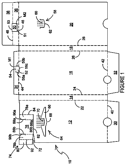
FIG. 1 is a side view of an exemplary cap device having a dust cover, chamber, and cap shell;
FIG. 2 is a side view of an exemplary assembled cap device before opening;
FIG. 3A is a cross-sectional side view of an exemplary cap shell;
FIG. 3B is a side view of an exemplary cap shell;
FIG. 4 is a side view of an exemplary chamber;
FIG. 5A is a cross-sectional side view of an exemplary shell and chamber with continuous and interrupted beads prior to actuation;
FIG. 5B is a cross-sectional side view of an exemplary shell and chamber with continuous and interrupted beads after actuation;
FIG. 6 is a side view of an exemplary cap device having a dust cover, chamber with middle thread, and shell with thread;
FIG. 7 is a side view of an exemplary cap device having an elongated dust cover, elongated chamber with continuous beads, and shell with interrupted beads;
FIG. 8 is a side view of an exemplary cap device having a dust cover, chamber with tapered platforms, and a shell;
FIG. 9 is a side view of an exemplary cap device having a dust cover, chamber with alternative tapered platforms, and a shell;
FIG. 10 is a side view of an exemplary cap device having a dust cover, chamber with protrusions, and a shell;
FIG. 11A is a side view of an exemplary cap device having a dust cover, chamber, and a shell with a two-arm cutting element;
FIG. 11B is a bottom view of the shell with a two-arm cutting element;
FIG. 12A is a side view of a cap device having an exemplary reusable dust cover with a plug seal, a chamber, and a shell;
FIG. 12B is a detail view of the reusable dust cover with a plug seal associated with the shell;
FIG. 13 is a side view of an exemplary cap device having a dust cover, chamber, and shell with a shell basket flush with the bottom of a shell chimney;
FIG. 14A is a side view of an exemplary cap device having a dust cover, a chamber with a pump seal, and shell;
FIG. 14B is a detail view of the pump seal portion of the chamber depicted in FIG. 14A ;
FIG. 15A is a side view of an exemplary cap device with a chamber having locking protrusions and a shell with shell gaps;
FIG. 15B is an alternative view of the chamber and shell of FIG. 15A ;
FIG. 15C is an open top view of the cap device depicted in FIG. 15A showing the chamber associated with the shell in an unactuated and actuated view;
FIG. 16A is a side view of an exemplary cap device having a dust cover, chamber with cutting element disposed on the top wall, and a shell with a foil disposed on a bottom opening;
FIG. 16B is a side view of the cap device of FIG. 16A showing an actuated chamber with cutting element in the shell;
FIG. 17 is a side view of an exemplary cap device having a dust cover, a chamber with cutting element disposed on the lower portion, and a shell with a foil disposed on a bottom opening;
FIG. 18 is a side view of an exemplary cap device having an enlarged width chamber, and a shell with an enlarged width chimney;
FIG. 19 is a side view of an exemplary cap device having a chamber with threads and locking beads and a shell with threads and locking beads;
FIG. 20 is a side view of an exemplary chamber with a drink-through top portion and shell with beads;
FIG. 21 is a side view of an exemplary cap device having a shell with a shell flange and shell chimney protruding below the shell flange having outer threads;
FIG. 22 depicts an exemplary cap device chamber associated with a resusable container;
FIG. 23 is a side view of an exemplary cap device with a piercer with a cutting element and a shell;
FIG. 24 is a side view of an exemplary cap device having a piercer with a cutting element, a shell with shell protrusions, and a shell base;
FIG. 25 is a side view of an exemplary cap device having a dust cover, a drink-through piercer with a cutting element, and a shell;
FIG. 26 is a side view of an exemplary cap device having a dust cover, a drink-through piercer with a cutting element, a shell with shell protrusions, and a shell base;
FIG. 27 is a side view of an exemplary cap device having a dust cover, a chamber with discontinuous threads and beads and a shell with a tamper evidence band, discontinuous threads, and beads;
FIG. 28A is a side view of an exemplary cap device having a chamber with chamber locking protrusions and a tamper skirt, and a shell with shell gaps;
FIG. 28B is a side view of the cap device of FIG. 28A with an assembled chamber and shell;
FIG. 28C is a side-top view of the cap device of FIG. 28A ;
FIG. 29 is a side view of an exemplary cap device having an elongated dust cover, a chamber, and a shell with a dust cover seat on the lower portion of the shell base; and
FIGS. 30-33 are side views of exemplary cap devices each having a dust cover, a chamber with an outer skirt and outer structures disposed on the outer skirt, and a shell.
Detailed description
A cap dispensing device can contain a chamber for housing a required amount of additional ingredients. The chamber can have any required volume, for example, about 5 mL to about 20 mL, about 10 mL to about 15 mL, or about 13 mL; for solids with a density of about 0.8 g/mL, this equates to a solid capacity of about 4 g to about 16 g, or about 8 g to about 12 g, or about 10 g. The chamber need not contain any particular type of ingredient. In one aspect, an ingredient can be added to the chamber to prevent or avoid caking of the composition (e.g., rice powder, silicon dioxide, glidant etc.). When an ingredient is present in the chamber, the ingredient typically takes up about 90% or less, or about 80% or less, or about 75% or less, or about 70% or less, or about 65% or less, or about 50% or less of the total available volume of the chamber. For example and without limitation, about 2 grams of solid can be contained in an exemplary chamber, sized such that the about 2 grams of solid takes up about 60% of the total available volume of the chamber
The chamber can include one or more side walls and one or more top walls attached to the one or more side walls. The chamber can also include an opening opposite the one or more top walls. In another aspect, the chamber can have at least two openings. At least part of any opening can be covered by a film, which can be any type of film known in the art. For example, the film can include at least one of a plastic film, a metal film, a foil film, a paper film, and a film containing a combination of the foregoing (e.g., a metalized plastic film). The film can be, for example, a bi-axially oriented film of polypropylene or metalized polypropylene. The film can provide a barrier to at least one of moisture and oxygen. The film can be made of a material that does not increase the actuation force (i.e., the force required to depress the chamber into the shell), for example, a material designed such that only a trivial amount of force is required to pierce and break the film when the film engages a cutting element. The film can cover a part of an opening, or it can cover an entire opening.
The one or more side walls of the chamber can include at least one to three continuous beads. The continuous beads can include an uppermost continuous bead, a middle continuous bead, and a lowermost continuous bead. Each of the at least one to three sets of continuous beads can extend along the entire exterior distance around the one or more side walls. A lowermost continuous bead can be a first distance from the opening, a middle continuous bead can be a second distance from the opening, and an uppermost continuous bead can be a third distance from the opening. The third distance can be greater than the second distance, which in turn can be greater than the first distance. Alternatively, the continuous beads can be replaced with continuous threads. In another aspect, the beads or threads are discontinuous or interrupted.
The one or more side walls of the chamber can be tapered so that the distance around the one or more side walls of the chamber is narrower near the opening opposite the top wall than at the top wall. The chamber can have one or more side walls with a lower portion and an upper portion. In one aspect, the width of the lower portion is greater than the width of the upper portion. The increase in width from the lower portion to the upper portion can be a smooth continuous taper or it can be stepped or discontinuous forming one or more platforms on the one or more side walls. In another aspect, described taper is disposed on one or more inner side wall of the chamber.
In another aspect, the width of the upper portion is greater than the width of the lower portion. The increase in width from the upper portion to the lower portion can be a smooth continuous taper or it can be stepped or discontinuous forming one or more platforms on the one or more side walls. In one aspect the difference in width between the upper portion and the lower portion is at least about 10 points or at least about 50 points. In another aspect, the difference in width between the upper portion and the lower portion is from at least about 1 to about 100 points. In another aspect, described taper is disposed on one or more inner side wall of the chamber.
The one or more side walls of the chamber can have one or more protrusions disposed therein to, for example, facilitate the flow of liquid in the chamber. The term “protrusion” can refer to, for example, any elevation, inversion, bump, bead, or thread in the side wall such that the movement of a liquid or particle in the chamber will be altered, diverted, or redirected. In one aspect, the at least one protrusion is disposed on one or more inner walls of the one or more side walls of the chamber. In another aspect, the protrusion may be disposed on a top or bottom wall of the chamber. In yet another aspect, the protrusion is continuous or discontinuous line. In another aspect, the protrusion may be of any suitable shape or pattern including linear, circular, rhomboid, square, random, or rectangular. In another aspect, the protrusion is at least 0.25 millimeters in height.
The chamber can be made with a pump seal disposed on the outer portion of the one or more side walls of the chamber. In one aspect the pump seal is disposed around the entire perimeter of the lower portion of the chamber. In another aspect, the chamber is made of two or more types of plastic that can be molded together. In a further aspect, one plastic can be rigid and a second plastic can be flexible (e.g., used for the pump seal). The pump seal can minimize or prevent, for example, the retention of liquid between the shell and chamber.
In one aspect the one or more side walls of the chamber are formed from a rigid substrate (e.g., PP (poly propylene), HDPE (high density polyethylene), metal or the like)). In another aspect, the pump seal is made of an elastic sealing material (e.g., all food safe elastomers including but not limited to food safe silicone). In this aspect, the pump seal substantially eliminates or minimizes any liquid retained between the shell and chamber. Alternatively, a flexible material (e.g., TPE, rubber band and the like) can be used in place of the pump seal.
In another aspect, the chamber can be multi-layered using different sealing materials. These sealing materials can be added at any suitable point in the manufacturing process (e.g., pre-mold or post-mold). In one aspect, a material used to make the chamber can absorb moisture (e.g., a desiccant). In another aspect, the material can prevent or reduce the adherence of ingredients in the chamber to the chamber walls (e.g., stainless steel, silicon, paper, and mica). Additional materials can be used to provide an improved moisture and/or oxygen barrier (e.g., polypropylene, metal, aluminum, and ethylene vinyl alcohol).
The chamber can be actuated (e.g., moved in any direction) and disposed inside a shell. In one aspect, the chamber is actuated with a force sufficient to dispose the chamber inside a shell. In another aspect, the force is sufficient to abrade, pierce, cut, or remove a film covering an opening in the chamber. In another aspect, the shell or chamber can provide resistance to actuation of the chamber into the shell to prevent, for example, accidental actuation of the chamber into the shell (e.g., before actuation is desired, for example, during transportation of storage).
The shell can include a shell base for engaging the opening of a container, for example, a beverage or cosmetics container. The shell base can engage the opening of the container, for example, to provide a leak resistant seal with the opening of the container. The leak resistant seal can be made tamper evident, for example, by including a tamper band in the shell base. The shell can also include a shell chimney disposed, for example, in the shell base for engaging with a chamber. In one aspect, there is substantially no space between the shell base and the shell chimney to, for example, minimizes retention of liquid between the shell base and the shell chimney.
The shell can include a shell basket disposed, for example, below the cutting element. In one aspect, the shell basket can be used for moving the cut film away from the chamber opening after it is pierced or cut by the cutting element. In another aspect, the shell basket protrudes below the shell base. In this aspect, for example, the shell basket may partially protrude into the container. In yet another aspect, the shell basket is substantially flush with the bottom of the shell chimney. This aspect may be advantageous in simplifying manufacture and molding of the cap device resulting in, for example, lower manufacturing costs. In another aspect, a shell basket that is substantially flush with the bottom of the shell base may facilitate the installation of a plug seal or TPE seal or the like (e.g., by compression molding), minimize leakage, and permit use of an unscrewing mold (e.g., to enhance thread consistency and profile.
After the chamber is actuated, it may be inserted into the shell such that the top of the chamber is flush or nearly flush with the top of the shell. In another aspect, the height of the chamber is elongated or increased to facilitate the removal of the chamber after, for example, actuation of the chamber. In this aspect, the height of the chamber with respect to the top of the shell after the chamber is actuated is sufficient to permit removal of the chamber from the shell using human hands. In another aspect, the height of the chamber with respect to the top of the shell after the chamber is actuated is at least about 1 cm.
In another aspect, a clip (e.g., handle, pull tab, projection or the like) can be attached to the top of the chamber in order to facilitate removal of the chamber from the shell. In this aspect, even if the top of the chamber is flush with or recessed below (e.g., 2 or more centimeters) the top of the shell after actuation of the chamber into the shell, the user can engage the clip to facilitate removal of the chamber in order to, for example, consume or use the product in the container or replace the chamber in the shell with a new chamber. In another aspect, the clip can be embedded in the top of the chamber in a groove such that the clip will not interfere with the normal operation of the chamber but can be accessed with human fingers. In this aspect, the clip can be lifted or pulled into a position where the clip can facilitate removal of the chamber from the shell. The clip can be made of any suitable material (e.g., TPE, plastic, metal etc.) and may be of any suitable shape (e.g., loop, circular, square, rectangular, rhomboid, triangular, etc.).
In another aspect, a separate chamber actuator can be provided. The chamber actuator can be adapted to engage with the chamber to assist the consumer in actuating the chamber into the shell. This aspect may be useful for consumers who would otherwise have difficulty applying the actuation force needed to actuate the chamber into the shell and pierce or cut the film.
In another aspect, the cap devices described herein can be adapted to be used with a container or a beverage making machine or device. For example, the replaceable chamber or shell can have threads disposed on the bottom or top portion adapted to engage with a container and also be adapted to be disposed in a commercial or consumer grade brewing or drink machine. When used with a commercial or consumer grade brewing or drink machine, a cutting element in the chamber or shell as described herein can pierce or cut the film and liquid can be provided by the brewing or drink machine. The liquid can be mixed with the composition in the chamber or shell and be deposited in a cup in the same manner as the brewing or drink machine is conventionally used. Alternatively, a cutting element in the brewing or drink machine can be used to pierce the film in the chamber or shell. In another aspect, a mechanism in the brewing or drink machine can pierce a film in the chamber or shell and shake or vibrate the chamber or shell to dispense the ingredients which are mixed with a liquid and dispensed into a cup or container to receive the finished beverage. In this aspect, chambers and shells containing compositions can be provided individually or in packages with multiple chamber and shells. The chambers and shells can be for single or multiple uses.
A cutting element can be associated with the shell, and can be, for example, disposed within the interior of the shell. The cutting element can be designed for at least one of piercing and cutting the film. Piercing, cutting, or piercing and cutting the film can be performed in such a manner that the cut film is displaced from the opening in the chamber and allows communication between the chamber and the shell.
The cutting element can include one or more edges. The one or more edges can be disposed at an angle with respect to the side walls of the shell. The angle can be, for example, a right angle, and acute angle, or an obtuse angle. The one or more edges may be of any suitable shape (point, square, triangle etc.) and any suitable degree of sharpness. The degree of sharpness can be adjusted, for example, to change the actuation force required to pierce or cut the film. The cutting element can include one or more of a point for piercing the film, a cutting mechanism for cutting the film, and a basket for moving the cut film away from the opening. One or more of the point and cutting mechanism can form all or part of the basket. The cutting element can include at least two arms which associate the cutting element with the shell. The angle between the at least two arms and the shell can be any suitable angle. In one aspect, the angle is from about 1 to about 90 degrees.
Alternatively, the cutting element can be associated with the chamber, and can be, for example, disposed within the interior of the chamber, for example, on a top wall, the middle, or on a lower portion of the chamber. The cutting element can be designed for at least one of piercing and cutting a film associated with, for example, an opening in the shell. Piercing, cutting, or piercing and cutting the film can be performed in such a manner that the cut film is displaced from an opening in the shell to allow communication between the shell and a container associated with the shell. In one aspect, the cutting element is disposed on a flexible top wall of the chamber. The cutting element can be actuated, for example, by applying a force to the top of the flexible chamber which pushes or actuated the cutting element in a downward manner toward the film.
The cutting element can include one or more sharp edges. The one or more sharp edges can be disposed at an angle with respect to the side walls of the shell. The angle can be, for example, a right angle, an acute angle, or an obtuse angle. The cutting element can include one or more of a point for piercing the film and a cutting mechanism for cutting the film. The cutting element can include at least two arms which associate the cutting element with an inner side wall of the shell.
The shell can also include at least three sets of locking beads on the one or more side walls. In another aspect, the shell includes at least three sets of locking beads on the one or more side walls. Each set of locking beads can include one or more locking beads, for example, a plurality of locking beads. The at least three sets of locking beads can include an uppermost set of locking beads, a middle set of locking beads, and a lowermost set of locking beads. The at least two sets of locking beads can include an upper set of locking beads and a lower set of locking beads. Each of the individual locking beads within a set of locking beads can be located at substantially the same vertical distance from the shell base.
For example, the uppermost set of locking beads can be disposed around the one or more side walls in such a manner that each of the beads in the uppermost set is approximately a first distance from the shell base. Similarly, each bead of the of middle set of locking beads can be disposed around the one or more side walls so that each of the beads in the middle set of beads is approximately a second distance from the shell base, and each bead of the of lowermost set of locking beads can be disposed around the one or more side walls so that each of the beads in the lowermost set of beads is approximately a third distance from the shell base cutting element. The first distance can be greater than the second distance, which in turn can be greater than the third distance.
With respect to the at least two sets of locking beads, the upper set of locking beads can be disposed around the one or more side walls in such a manner that each of the beads in the upper set is approximately a first distance from the shell base and each of the beads in the lower set is approximately a second distance from the shell base.
Each of the at least three sets of locking beads or the at least two sets of locking beads can be on the interior of the one or more side walls of the shell, for engaging with the continuous beads of the chamber. The one or more beads of each of the at least three sets of locking beads or the at least two sets of locking beads can have, for example, an interrupted design wherein there are spaces between the beads. Unexpectedly, the inventors have found that an interrupted design can allow for an acceptable fit with the continuous beads of the chamber without unacceptably increasing the stiffness of the shell. In one aspect, an unacceptable increase in the stiffness of the shell can give rise to manufacturing difficulties.
The locking beads can be of any size sufficient to engage the continuous beads of the chamber. The locking beads and continuous beads can provide a leak-resistant fit. Thus, the tightness of the fit between the locking beads and the continuous beads, which can be correlated to the actuation force required to depress the chamber, can provide an appropriate balance of ease of actuation and acceptable leak resistance. A tight fit between the locking beads and the continuous beads can be associated with a high degree of leak-resistance and a high actuation force. That is, while a tight fit provides high leak resistance, it also increases the force required to overcome the fit between the continuous beads and the locking beads when depressing the chamber. Thus, if the actuation force is too high, then a customer may have difficulty actuating the chamber. A loose fit between the locking beads and the continuous beads can be associated with a low degree of leak-resistance and a low actuation force, which can lead to both unacceptable leaks and to inadvertent actuation, for example, during shipping, storage, stocking, etc.
The inventors have unexpectedly found that the fit between the locking beads and the continuous beads can provide an actuation force of about 10 pounds to about 30 pounds, or about 20 pounds to about 30 pounds, or about 20 pounds to about 26 pounds and also provide both good leak resistance and acceptable ease of actuation. This force can be achieved, for example, by using locking beads and continuous beads that protrude from about 0.005 inches to about 0.015 inches, or about 0.008 inches to about 0.010 inches from the shell and chamber, respectively. For example, if the shell and/or chamber that has an inner thickness (i.e., the thickness of the shell and/or chamber in locations where no beads are present) of about 0.975 inches, then the outer thickness (i.e., the thickness of the shell and/or chamber plus the additional thickness provided by the beads) can be about 0.983 inches to about 0.985 inches, or about 0.985 inches, or about 0.984 inches, or about 0.983 inches. When the one or more side walls of the chamber are tapered as described above, then, for example, the lowermost set of locking beads can protrude about 0.008 inches from the shell, the middle set of locking beads can protrude 0.009 inches from the shell, and the uppermost set of locking beads can protrude, for example, 0.010 inches from the shell. Similarly, the uppermost continuous bead in the one or more walls of the chamber can have the smallest protrusion (e.g., 0.008 inches) from the one or more walls of the chamber, the middle continuous bead in the one or more walls of the chamber can have an intermediate protrusion (e.g., 0.009 inches) from the one or more walls of the chamber, and the lowermost continuous bead in the one or more walls of the chamber can have the greatest protrusion (e.g., 0.010 inches) from the one or more walls of the chamber.
In another aspect, the inventors have also unexpectedly found that two continuous beads and two sets of locking beads can provide both an acceptable leak resistance and actuation force.
In another aspect, threads can be used in place of the at least two and at least three sets of locking beads. In this aspect, shell threads can be disposed on the shell chimney continuously or discontinuously from the top portion of the shell chimney to the lower portion of the shell chimney. In another aspect, the chamber has one or more side walls, the one or more side walls having a top portion, a middle portion, and a lower portion. Chamber threads can be disposed on the middle portion. The chamber threads are adapted to sealably or rotatably engage with the shell threads (e.g., engage such that liquid retained between the chamber and the shell is substantially eliminated or minimized).
In one aspect, the chamber has chamber threads disposed on the one or more side walls. The chamber threads can, for example, be continuous threads or broken threads (e.g., FIG. 19, 406 ). This aspect also provides a shell with shell threads and optional beads disposed on the shell chimney. In this aspect, when the chamber threads engage with the shell threads, the chamber cannot be readily actuated into the shell. When the chamber is rotated with respect to the shell, for example beyond the length of the chamber threads and the shell threads, the chamber threads disengage from the shell threads. When the chamber threads disengage from the shell threads, the chamber is capable of being actuated into the shell. In one aspect, after the chamber threads disengage from the shell threads, the chamber can engage with the beads disposed on the shell to facilitate actuation of the chamber into the shell. In this aspect, for example, a dust cover is not needed because the chamber is in a “locked” position until the chamber is rotated and the chamber threads disengage from the shell threads.
In another aspect, the shell has locking slots (e.g., depressions, hole, gaps) adapted for receiving locking beads disposed, for example, on the chamber, a shell skirt, and a cutting element. This aspect also provides a chamber with locking beads and locking protrusions disposed on the side walls. Initially, the locking slots on the shell are not aligned with the locking protrusions on the chamber and the chamber cannot be readily actuated into the shell. In another aspect, the chamber can be rotated with respect to the shell in order to, for example, align the locking slots on the shell with the locking protrusions on the chamber. In this aspect, when the locking slots on the shell are aligned with the locking protrusions on the chamber, the chamber can be actuated and inserted into the shell wherein the cutting element can pierce the film. In another aspect, the chamber can be further rotated with respect to the shell until the locking slots are no longer aligned with the locking protrusions. In this aspect, the chamber is “locked” with respect to the shell and the chamber cannot readily be removed from the shell. In this aspect, a dust cover may not be needed since the chamber is initially “locked” until the locking slots on the shell are aligned with the locking beads on the chamber.
The description continues in the full USPTO document.
 Lapsed, fee not paid8 drawings