 Lapsed, fee not paid7 drawings
Cameras, Displays & Optics · US 9,918,061 B2
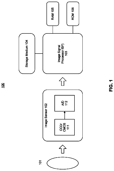
System and method for storing image data in parallel in a camera system
System and method can support an image signal processing apparatus, such as a camera system.
US 9,918,070 B2 · Assignee: Beistar3D Limited · Inventors: Pavol; Janík
Sheet 1 of 23 from the published document. All sheets in the USPTO PDF
A method of description of points of an object from object space is disclosed, wherein for each point of the object of object space displayed on a graticule of a scanning device, information about point distance from the scanning device is registered and then stored to each point of the graticule of image as additional data. Furthermore, connection for implementation of said method covering a scanning device is disclosed, wherein a scanning system consists of at least two scanning devices connected to inputs of CPU central control unit, which includes a block of software applications and a block of computing module with evaluation software, whereas communication of the block of software applications and the block of calculation module with the evaluation software with CPU occurs via data buses, whereas CPU outputs are connected both on a block of internal memory and/or removable memory and a block of online outputs.
People use eyes for viewing of surrounding world and the human beings are able thanks to eyes to navigate within space based on information about scene depth. Dimensional (stereometric) perception of a static image, which is produced in human brain when viewing two planar displaced images of the same scene, was already described in 1830s by Sir Charles Wheatstone. We are not able to clearly distinguish depth information when viewing two-dimensional image. In the case of vision with one eye, one is able to perceive depth on the basis of monocular phenomena only. Two eyes are required to view three-dimensional (stereoscopic) images. Binocular vision is perceiving of scenes or images with both eyes. Resulting images are reflected on retina and brain reconstructs the same to perception of dimensional appearance. Stereoscopy is a branch involved in displaying of dimensional images or frames w
1 of 23 drawing sheets so far from the published document, cropped to the drawing. Every sheet is in the USPTO PDF.
What the patent claimed, word for word. All of it is now free to use.
The invention relates to the method for description of object points of the object space and registration of image information and connection for its implementation.
People use eyes for viewing of surrounding world and the human beings are able thanks to eyes to navigate within space based on information about scene depth. Dimensional (stereometric) perception of a static image, which is produced in human brain when viewing two planar displaced images of the same scene, was already described in 1830s by Sir Charles Wheatstone. We are not able to clearly distinguish depth information when viewing two-dimensional image. In the case of vision with one eye, one is able to perceive depth on the basis of monocular phenomena only. Two eyes are required to view three-dimensional (stereoscopic) images. Binocular vision is perceiving of scenes or images with both eyes. Resulting images are reflected on retina and brain reconstructs the same to perception of dimensional appearance. Stereoscopy is a branch involved in displaying of dimensional images or frames whereas two frames created for left and right eye are called a stereo pair. Stereoscopic video frequency is viewing of a sequence of consecutive frames. Recently, stereoscopy has been widely applied in different scientific branches, in the field of entertainment industry or elsewhere. It is known that visualization technologies have been long used for three-dimensional (stereoscopic) imaging. These systems do not project just one image for both eyes but try to project one of a pair of separated views for each eye. Stereoscopic imaging of two images displayed next to each other is known. Historically, it is the oldest method used still today. Using stereo-viewers (so-called stereoscopes), two static images captured by cameras horizontally shifted by eye span (about 7 cm) and placed next to each other are viewed with glasses. Similarly to audio technology, this distance is usually called as stereo basis. Special cameras with two lenses were and are produced for these purposes. Thanks to digital imaging, the required shifted images can be created using special software applications from a digital image. Glasses allow either direct (where right eye views right component image and left eye views left component image) or cross viewing of the shifted images (where right eye views left component image and left eye views right component image). Experiments showed that the “crossed” viewing is what allows expansion of the field of vision and improvement of stereoscopic effect depth. Glasses with special prismatic optics have been developed for this imaging. In this case, the component images are crossed as well. The principle works also for movable images and therefore, it is theoretically applicable for television, however, special horizontal scanning is required. The advantages of these systems include sufficient brightness of resulting image because the contributions of brightness of the component images are fully added. The component images are often picture slides. Another of these 3D imaging principles is stereoscopic imaging of superposition of two shifted images (Anaglyph system). The viewed image consists of superposition of two component images (so-called anaglyph) concurrently taken by two cameras that are again horizontally shifted by distance of eyes and therefore, project a scene under different angles. In cinematography or project television screen, the component images are projected on canvas via colour filters (cyan and red). A viewer watches the screen with glasses with corresponding colour glasses. This colour filtration makes sure that each eye perceives just a component image and the brain produces spatial perception. This method of separation may in case of colour images distort colour perception of resulting virtual image. Many versions of this system have been gradually developed. One of them is for example Color Code 3D system where different colour combination is used (yellow-dark blue in filters of projectors and amber-dark blue in filters of glasses). Anachrome Method should be mentioned as well with substantially narrower stereo basis aiming at possibility to view anaglyph even without glasses—without dimensional perception, of course. A disadvantage of this method is—except for necessity of using special glasses—small permissible deviation from viewer's position from the image axis at which the spatial perception (stereoscopic effect) shows. Today, in the era of digital photograph, there are many software applications to produce anaglyph from a standard 2D digital image. Another method for viewing is 3D glasses fitted with variously polarized filters (with orthogonal or circular polarization). Also in this case, the resulting image consists of concurrent superposition of two component images taken by shifted cameras. The superposition is created on the projection screen by projection from two projectors fitted with polarization filters with different orientations or polarization directions. Viewer watches the screen with glasses with corresponding polarization filters of different polarization for each eye. Advantage of this somewhat more expensive method is reduced colour distortion of the colour perception. However, the projection screen is very expensive (specially treated silver canvas) because it may not change to polarization of incident and reflected light flux (depolarization).
Fundamental disadvantage of the solutions described above is the problem of time discontinuity of signals received by brain from eyes. The reason for this time discontinuity is the fact that signals going through left and right eye reach the brain vision centre with a time shift. This results in brain instability due to unnatural receipt of image signal. The vision centre must process the discontinued signal and the centre is not made for it. The consequences of this processing of received information may include epileptic fits or headaches. An alternative is successive stereoscopic imaging of the component images with eclipsing (Eclipse Method). The component images taken by shifted cameras are displayed on a display or projected to a projection screen successively. Their sequence may be equal to e.g. a period of half-frames. To reduce distortion in case of sequences of images of quick content change, the alternating period can be reduced—e.g. using 100 Hz exposition. Luminophores of the display (particularly green) or the projection screen used must not show long afterglow for the same reason. Also special glasses are required in this case. Apertures of left and right eye are successively eclipsed and opened in a synchronized way with alternating of the component images. The required synchronizing signal is usually emitted in the IR radiation band and this may practically restrict the viewing space and number of viewers. Technical applicability can be provided e.g. by LCD SH Shutter Glasses). For this version, the viewing angle is wider. For the last described method, signal is emitted concurrently from the first and second projector and the only difference between the signals is that one image has blue component blocked and the other has red component blocked. Because human eye is the most sensitive to green colour (up to 70% of image information consists of green colour), brain gets confused and human perceives the image as stereo image albeit slightly shifted in colour tones. Of course, this presents a different perception load but the problems described above (headache and epileptic fits) are mitigated. The last of the described methods could be implemented in passive asynchronous form where viewer's glasses function control is not required. In this case, the component images are projected in a time sequence by two projectors equipped with polarization filters with different polarization directions. The viewers use the glasses with corresponding polarization filters of different polarization for each eye similarly to the method described earlier. Disadvantage common for all 3D systems described in this section is the necessary use of special glasses. In addition, bibliography describes “Mesh-Based Depth Coding For 3d Video Using Hierarchical Decomposition Of Depth Maps”, Sung-Yeol Kim and Yo-Sung Ho, Gwangju Institute of Science and Technology (GIST) 1 Oryong-dong Buk-gu, 500-712, Gwangju, Korea). This article describes the process for 3D imaging based on a structure of triangle fields connected into the structure of a planar grid. The system is based on taking with right and left camera. Then, the photos taken from left and right camera superpose and where the image areas can be mutually defined and calculated, a triangle of single colour is defined with at least several points in each direction. Considering the side shift of right and left image it could be calculated which of the triangles would be higher and lower. The triangles being virtual and placed in a virtual centre produce a compact area that breaks depending on the space squeezing system. In this way, partial image plasticity could therefore be created. Whereas this triangle grid may behave, for example as metal sheet surface in a press mould, certain image profiling could be achieved, however, it is in no way possible to achieve neither high image depth dynamics as required for real imaging nor precise point structure. The problem is that surface is calculated by the areas of triangles and their squeezing up or down produces the illusion of space. However, this is still the compact grid with differently deformed triangle fields being unable to produce visual image fidelity. This system can work only as a demonstration of possibilities of the triangle fields when profiling of 2D image. However, it is important that when viewing the deformed 2D space, human beings cannot see a 3D image but partially profiled imprint of image surface only, created by colour areas and therefore without possibility of any definition of image details. No image definition in full depth dynamics occurs here but only a few per-cents when compared to real three-dimensional perception. In addition, the profiled image is created by triangle fields as non-existing central image with triangle structure of squeezed colour areas. This is a demonstration of possibilities of using the technology that is commonly only used in computer games. However, this technology is built for creation of virtual reality. Based on this procedure and calculation of the triangle grid it is almost impossible to get 3-D imagining being able to convince a human eye that it watches a real image.
The aim of the invention is designing of a new way for description of points from the object space that would allow working in 3D without necessity of using of additional optoelectronic or other aids.
The disadvantages mentioned above are removed and the aim is achieved by the method of description of the object point from the object space, substance of which is that information about distance from scanning device is recorded for each subject point of the subject space displayed on the graticule of a scanning device and information created in this way is saved to each image graticule point as additional data.
It is favourable for perfect description of the object points in the object space when distance information “I” is recorded using at least two scanning devices arranged at a certain distance from each other.
Furthermore, it is favourable when distance information “I” from the graticule point in “z” axis direction from the object point of the object space to the image graticule point is registered for each object point.
It is favourable for exact description of the objects in the object space containing the eclipsing points of different translucence level when information about their distances “I” from scanning devices is recorded for the object points of the object space containing the eclipsing points of different translucence level, whereas brightness and colour information of the eclipsing points is recorded at the same time in conjunction with the translucence level of said layer point and information generated in this way is stored to the image graticule point.
Depth information about other distances of these points from the scanning device is assigned for an image displaying several superposed areas of the layer points of different translucence level and different depth information and at the same time, brightness and colour information of the image points in conjunction with the point translucence level in the layer is recorded and information produced in this way is stored to each image as additional data.
The grounds of the invention is that the following information is added to each image information coded by any known codec: information about distance of each frame or image point (pixel) from the object space from the scanning device (depth imprint) either individually or in groups. information about the eclipsing points hidden in the image point axis behind the depth imprint points of different translucence level and different “I” distance, e.g. a scene behind imperfectly translucent glass, fog etc. information about the eclipsing points behind the edges of opaque points because there may be the eclipsing points of internal brightness and colour information and internal “I” distance from the scanning device behind each opaque point.
The advantages of this solution are 100% backward compatibility with existing systems of coding and image data transfer. The method of registration according to this invention allows current professional technology to work, among others, with this data as with 2D image, to edit and cut in 2D with subsequent conversion into real 3D image using information from additional data created based on our design. Combination of necessary data is not problem both with respect to adequate codecs, which store colour components of each image point directly, including broadcasting standards, and current compressed broadcasting standards that use disproportional division of brightness and colour component, so-called chroma sampling (from the most common variant 4:2:2 through all other variants and combinations, including non-standard ones such as 3:1:1 HDCAM)
Current recording of the chroma subsampling:
4:4:4:4 4: point position on axis X and axis Y
4: point colour information 4: point brightness information 4. point brightness information for brightness levelling across the image 4:4:4 4: point position on axis X and axis Y 4: point colour information 4: point brightness information 4:2:2 4: point position on axis X and axis Y 2: point colour information 2: point brightness information 4:2:0 4: point position on axis X and axis Y 2: point colour information 0: point brightness information 4:1:1 4: point position on axis X and axis Y 1: point colour information 1: point brightness information Based on information about depth imprint according to this invention, the record would be as follows: 4:4:4:4+depth information 4:4:4+depth information 4:2:2+depth information 4:2:0+depth information 4:1:1+depth information 4:4:4:4+depth information+4:4+depth information 4:4:4+depth information+4:4+depth information 4:2:2+depth information+2:2+depth information 4:2:0+depth information+2:0+depth information 4:4:4:4+depth information+4:4+depth information+4:4+depth information 4:4:4+depth information+4:4+depth information+4:4+depth information 4:2:2+depth information+2:2+depth information+2:2+depth information 4:2:0+depth information+2:0+depth information+2:0+depth information
It is advantageous that 3D image format compiled in this way would mainly be the output of different devices from professional camcorders up to basic mobile phones, computers and tablets for consumer market.
Then, identical format may be used as input for further processing in special cut applications for video processing or corresponding graphical software for working with still images; at the same time, it would be output format as well.
Equally, the 3D image format would be used as input format for 3D imaging devices or units adapted for this purpose.
Finally, it is suitable also for storing and archiving of image data because it allows fully-fledged recording of three-dimensional scene from which simplified forms can be effectively produced, if needed (e.g. 2×2D format image for current “three-dimensional” projecting systems or imaging devices for stereograms or 2D format image for common imaging units or printing). The 3D format image according to this method is effective with respect to data flow (and therefore capacity of archiving device needed), generally thanks to saving of necessary overlaps only.
The advantage of the method according to this invention is that distance would be always assigned exactly (i.e. depth information) from the scanning device for each point of the object space. Should it be necessary to describe the object point on a place where chrominance information has saturation level under 100% (translucence is the matter) or a point not visible from the position of the scanning device, the description will consist of another “I” distance as well as brightness and chrominance information.
To precisely describe the object points of the object space, connection for implementation of the method according to previous method claims is used, which covers the scanning device substance of which is that the scanning system consists of at least two scanning devices connected to the inputs of CPU central control unit, which includes a block of software applications and a block of computing module with evaluation software, whereas communication of the block of software applications and the block of calculation module with the evaluation software with CPU occurs via data buses, whereas the CPU outputs are connected both on the block of internal memory and/or removable memory and the block of online outputs.
It is favourable for ensuring of the depth information of the object points of the object space and their assignment to the graticule points of the primary scanning device if the scanning device consists of the primary scanning device and at least one secondary scanning device.
It is favourable for description of the objects in the object space if the secondary scanning device consists of a radiation (distance) detector and a radiation emitter.
It is favourable for description of shape as well as colour of the objects in the object space if the primary scanning device or the secondary scanning device consists of a camcorder.
It is favourable when the radiation (distance) detector consists of a CCD or CMOS sensor fitted with optics and the radiation emitter consists of a laser.
It is favourable for description of the object points in the object space, either being colour- or shape-related from multiple view points up to 360° if at least three scanning systems are used, being arranged around the object (the object space) at a certain distance.
The connections designed in this way would allow correct definition and assignment of depth information data and create depth information of the object space. The scanning systems included in these connections allow to get and assign the depth information in a multiple of ways for each point of the object space, thus to create full depth information for each 2D image.
The invention will be explained using drawings, where
FIG. 1 shows selected point of image graticule of a scanning device,
FIG. 2 shows “I” distance of a specific graticule point, portrayed using “z” coordinate,
FIG. 3 shows the graticule point of a scanning device and “z” coordinate assigned with indication of specific “I” distance of the object point of the object space,
FIG. 4 shows the graticule point of a scanning device and “z” coordinate assigned with indication of specific “I” distances of the first and second object point of the object space,
FIG. 5 shows the object point of the object space visible by three scanning devices,
FIG. 6 shows the object point of the object space visible by two scanning devices,
FIG. 7 shows the object point of the object space visible by one secondary scanning device,
FIG. 8 shows the object point of the object space visible by the primary scanning device,
FIG. 9 shows the object point of the object space visible by the system of three scanning devices arranged against each other at 120° interval,
FIG. 10 shows the object point of the object space visible by the primary scanning device and radiation detector and emitter,
FIG. 11 shows basic block diagram of connection of the scanning system covering two scanning devices and connection of CPU with relevant service blocks,
FIG. 12 shows block diagram of connection of the scanning system, where the scanning device is the primary scanning device consisting of a camcorder and at least one secondary scanning device consisting of a radiation emitter and a radiation detector,
FIG. 13 shows block diagram of connection of the scanning system, where the scanning device is the primary scanning device consisting of a camcorder,
FIG. 14 shows block diagram of connection of the scanning system, where the primary scanning device is the primary scanning device consisting of a camcorder and the secondary scanning device consists of both a camcorder and radiation emitter and detector,
FIG. 15 schematically shows block diagram of connection of the scanning system, where the primary scanning device and secondary scanning device consist of a radiation emitter and detector,
FIG. 16 shows one embodiment of the assignment of identification of individual points of the image graticule on individual lines using the application software,
FIG. 17 shows 3D codec and the method of its registration based on what of three codec types would be used for combination with the “depth information”, and
FIG. 18 shows the object points of the object space shot by a system of three scanning devices arranged at a certain distance from each other. Calculation of the depth information is shown in FIG. 19 . Scanning angle definition “u” is shown in FIG. 20 . The block diagram showing how depth information is determined is shown in FIG. 21 . The 3D codec block diagram is shown in FIG. 22 . The block diagram for calculation of the depth information using the primary scanning device and the secondary scanning device consisting of the radiation emitter and detector is shown in FIG. 23 .
The invention will be explained in detail using the invention embodiments. Obviously, these examples are an indicative embodiment of application of principles behind this invention.
For the purpose of description of method and connection for implementation thereof according to this invention, we hereby give the following definition of terms used herein below in the following description.
Definition of terms used, whereas we work in 2D at the moment of scanning and use the following terms:
Scanning device—a device that scans the object space using image sensors and then records obtained data about the object space for the purpose of storing, processing or imaging of obtained data (by the scanning device within the definition of this invention may for example be a camera, camcorder, X-ray device, emitter and detector system and/or similar devices of this type) Image sensor—an electronic component (e.g. CCD chip or CMOS) consisting of a set of elements sensitive to light, arranged in a graticule that convers incident light radiation into electric signal Scanning device graticule—within this invention, a network of elements of the image sensor sensitive to light. Typically, these elements sensitive to light are arranged into a grid and the values shot by the elements are arranged in matrices during processing. Element sensitive to light—the smallest scanning unit of a image sensor, which captures image information about a section of the subject space (the smallest graticule unit) Object space—the space located in front of lenses of a scanning device. Shot objects are located in the object space. These objects may overlap or hide each other or they may be variously broken. They may be of different colour and translucence. Each object is characterized by its chromacity and translucence. Section of the object space—a part of the subject space captured by the element of the scanning device sensitive to light Image/frame—a representation of shot object space by a group of points of the image bearing image information. Image point (pixel)—the smallest image (frame) unit with image information (colour and brightness), which represents a section of the object space captured by one element of the scanning device graticule sensitive to light. Number of image points corresponds to the number of the scanning device (image sensor) graticule elements sensitive to light. We add the following terms for processing and conversion into 3D: Depth imprint of the object space—a set of “I” distances assigned to the image points (for which only brightness and colour information was known to date) from objects in the sections of the object space represented by them to the plane of the image sensor of the scanning device. These distances are obtained e.g. by triangulation during processing of at least two images taken from two different scanning devices. Just one distance is assigned to each image. Should the section of the object space include multiple objects characterized by their chromacity and translucency, where some of them are fully covered from the view of the image sensor or they are visible to a partial extent only thanks to translucence of closer objects, the image point gets the object distance assigned from this section of the object space being located as closest to the image sensor or the plane of the image sensor of the scanning device. In fact, the depth imprint therefore determines a shell of the object space. Depth imprint point—a representation of an object from component part of the object space located closest to the image sensor or the plane of the image sensor of the scanning device. Eclipsing point/eclipsing point of depth imprint point—in the sense of this invention, a representation of an object from component part of the object space located behind the depth imprint point in the section of the object space, i.e. located at the distance from the plane of image graticule of the scanning device exceeding the distance of the object from the component part of the object space located as closest to the plane of the image graticule of the scanning device. The point is defined by “I” distance from plane of the image graticule of the scanning device or from a specific point (depth imprint point or eclipsing point) behind which it is located, brightness and colour information or translucency. The number of these points is unlimited. Depth information—created by combination of depth imprint and information about eclipsing points. Hence, the depth information includes a lot of information required to identify individual objects in the object space and their placement within the object space, colour, brightness and translucency at the moment of scanning of the object space. 3D codec—for the purpose of this invention, a standard codec+information about depth information for each image point. Or data about depth information for other points on the “z” axis that define “I” distance of individual points from the scanning device with registration of their distances “I” on the “z” axis and brightness and chromacity information. Chromacity information—for the purpose of this invention, information about colour of said point View line—for the purpose of this invention, a line crossing Am and L or Am and P or Am and S points.
Generally, the method for description of the points 12 of the object 11 of the object space 1 according to this invention rests in the following steps. The first step is that for each object 11 registered in 2D format located in the object space 1 , depth information about its distance is registered for each of its point at the same using at least two scanning devices 3 arranged in a certain distance from each other and the second step is that the information produced in this way is stored to each image as additional data. As mentioned above for the object space 1 , e.g. image registered in 2D format, the depth imprint is added to the registered information about individual points 12 of the object—image from the object space 1 .
The fundamental arrangement of connection for the method according to this invention, which is scanning of individual points 12 of the object 11 located in the object space 1 , is shown on FIG. 11 . Connection in this arrangement includes a scanning system 2 that includes at least two scanning devices 3 . The scanning devices 3 are connected to inputs of the central processing unit 4 (hereinafter “CPU” only). CPU 4 integrates block of software applications 5 , which includes software application 51 for the radiation emitter 34 and detector 33 control and software application 52 for scanning devices 3 control and software application 53 for evaluation of points 36 of the graticule 35 and block of calculation module 6 with software application 61 is integrated as well. In addition, CPU 4 has some of its inputs connected to the block 7 of internal memory and/or removable memory and to block 8 of online outputs.
Communication between the scanning system 2 and the CPU 4 is described below. Shot data is brought from the scanning system 3 via calculation modules of radiation emitter 38 and detector 39 and/or image processors 37 to CPU 4 inputs and the latter communicates via the block of software applications 5 contained therein, software application 51 for communication with the radiation emitter 38 and detector 39 and/or radiation detector 12 , software application 52 for communication with image processors 37 of the primary scanning device 10 and/or secondary scanning device 11 and software application 53 for evaluation of points 36 of the graticule 35 as well as calculation module 6 for software application 61 for calculation of 3D codec. Using software application 53 for evaluation of points 36 of the graticule 35 , mathematical calculation of the depth information is performed and then, this distance information is saved to each point 12 of the object 11 as additional data and the depth imprint is created. Then, 3D codec is calculated using the software application 61 for calculation of 3D codec and written as additional data to a file and the 3D codec must be used to repeated imaging the file with additional data.
Another possible connection of the scanning system 2 for 3D scanning of the object 11 of the object space 1 , e.g. shot image according to this invention, is shown on FIG. 13 . The purpose of this connection is getting the depth information including definition of points 12 of the object 11 located outside angle of the primary scanning device 31 but visible by the secondary scanning device 32 . Connection of the scanning system 2 in this arrangement contains three scanning devices 3 , where one of them is the primary scanning device 31 , so-called central one and two secondary scanning devices 32 , so-called lateral one. The scanning devices 3 of the scanning system 2 are again connected to CPU 4 inputs. CPU 4 integrates block of software applications 5 , which includes software application 52 for the scanning devices 3 and software application 52 for scanning devices 3 control and software application 53 for evaluation of points 36 of the graticule 35 and block of calculation module 6 with software application 61 is integrated as well. In addition, CPU 4 has some of its inputs connected to the block 7 of internal memory and/or removable memory and to block 8 of online outputs.
This is one of possible embodiments. In practice, a different number of secondary scanning devices 32 may be used and they do not need to be installed on the same plane on a single axis with the primary scanning device 31 . However, it is necessary to have information about their mutual position in the space delimited by X, Y and Z coordinates. Furthermore, it is necessary to know the scanning angle “u” of the scanning devices 3 and the take angle “u” of the scanning devices 3 that sense the objects 11 in the object space 1 . Here, it must be known whether the view direction on the shot object space 1 using secondary scanning devices 32 either identical or different from the view direction to the object space 1 of the primary scanning device 31 and if different, by how many angles and in what direction. It applies to all conditions that the procedure for identification of the points 12 of objects located in the space and subsequent production of the depth information is identical. Quantity of data being processed changes only in case of different number of the secondary scanning devices 32 and depending on their placement within the space. The calculation principle does not change here, only some new values and formulas, which correct mutual position of the scanning devices 3 , will be added.
The scanning system 2 can be used with a pair or two pairs or with multiple secondary scanning devices 32 arranged in various distances from the central primary scanning device 31 . In this way, substantially deeper view is achieved and this may be rotated and edited during processing or projection. Based on knowledge of placement of each point 36 of the graticule 35 of the primary image, which is imaging of points 12 of the object 11 of the object space 1 and all points 36 of the graticule 35 of the secondary images, which are imaging of points 12 of the object 11 of the object space 1 , a mathematical formula would allow calculation of distance of each individual image point from plane (axis) on which the scanning devices 3 are arranged.
Another method for description of the points 12 of the object 11 of the object space 1 via the scanning systems 2 is shown on FIG. 9 . In this case, the scanning systems 2 are placed against each other at 120° intervals and in this arrangement (with at least 3 systems) it is possible to scan points 12 of the objects 11 in the object space 1 within 360° of their surface. We must know mutual position of the scanning systems 2 and the scanning angle “u” of these scanning systems 2 in this case. Each of the scanning systems 2 placed like this records an image from the primary scanning device 31 and the depth information. One of these scanning systems 2 we have selected is defined as the primary scanning system 2 of the full group of the scanning systems 2 . The following data is added to the primary scanning device 31 image for that scanning system we have defined as the primary scanning system 2 : the depth information from this agglomeration of the scanning systems 2 . It means that the image from the primary scanning device 31 from the primary scanning system 2 is completed with the depth information that contain image data for points 12 of the objects 11 in the object space from multiple points up to 360° view.
Should the scanning device 3 be fitted with zoom-allowed lenses, the zoom is characterized as proportion of the longest possible focal distance of the lenses to the shortest one. Hence, zooming is based on the lenses with ability to adjust focal distance of so-called zoom lenses or pancratic lenses. Optical zoom is change to the focal distance of lens made based on shifting of the lens. Change to the focal distance is achieved by rearranging of individual optical members in the lens of the scanning device. In doing so, individual optical groups move on spiral lines with certain gradient and move against each other thereby. Here, two embodiments for the zoom function are obvious. For the first embodiment, where the primary scanning device 31 only is fitted with the zoom feature, zoom information is transferred to CPU 4 by communication with the software application 53 for evaluation of points, whereas the secondary scanning devices 32 have their scanning angle “u” unchanged. Mathematical processing using the software application make all shot data in conformity with the focal distance (zoom) of the primary scanning device 31 .
For the second embodiment, the secondary scanning devices 32 will be fitted with zoom feature as well. Zoom may be either optical (see above) or digital.
Another embodiment for arrangement of the scanning system 2 for 3D scanning is shown on FIG. 14 . The scanning system 2 of this embodiment includes the central primary scanning device 31 with the secondary scanning devices 32 on left hand and right hand side (e.g. a camcorder with the central lens and a pair of CCD sensors with lens arranged on both sides of the primary scanning device 31 ) and the secondary scanning device 32 with the radiation emitter 34 and detector 33 , e.g. wave/particles emitter. The radiation emitter 34 and detector 33 , installed in the secondary scanning devices 32 , work either in the counter-tact mode or at different frequency. The radiation emitter 34 and detector 33 measure the distance of individual points 12 of the object 11 at the same time.
Shot distance data for individual points 12 of the object 11 are mathematically processed using the software application 53 for evaluation of points and assigned to individual image points. This embodiment improves calculation of the “depth information”. Distance additionally measured by the radiation emitter 34 and detector 33 is used as a check of calculation and eliminates potential calculation errors. The depth information for each image point of the primary scanning device 31 is then registered in the codec using the software application 53 for evaluation of the points.
Another embodiment with arrangement of the scanning system 2 is connection of the scanning devices 3 to the radiation emitter 34 and detector 33 , e.g. waves/particles emitter. This scanning system 2 can be used directly also outside the visible image spectrum, see FIG. 15 . This is a condition when it is necessary to scan the objects 11 in the object space 1 under conditions where there is no visible spectrum radiation or the radiation is weak enough to allow writing of the chromacity information and despite that, it would be necessary to produce the depth information even without the chromacity information. Should we use one scanning device 3 fitted with the radiation emitter 34 and detector 33 as primary and at least two scanning devices 3 fitted with the radiation emitter 34 and detector 33 as secondary, we can produce depth information containing all data except for chromacity, brightness and translucence data.
A specific embodiment is arrangement of the scanning system 2 for scanning of the objects 11 of the object space 1 with the use of a mobile phone or a tablet; see FIG. 12 as the scanning device 3 for scanning of the object 11 . The scanning system 2 consists of two scanning devices 3 . Connection of the scanning system 2 in this embodiment contains only two scanning devices 3 , one of them is the primary scanning device 31 , so-called central, consisting of camcorder and the second is the secondary scanning device 32 , so-called lateral one, consisting of the radiation emitter 34 and detector 33 , for example waves/particles emitter.
The description continues in the full USPTO document.
About 6,371 words. The USPTO PDF has it with every drawing.
Fees are due 3.5, 7.5 and 11.5 years after grant. This patent expired on March 13, 2026, so the fee marked "not paid" was the one that went unpaid.
Method for description of object points of the object space and connection for its implementation
Filed May 2013 · published Jul 2015Method for description of object points of the object space and connection for its implementation
Filed May 2013 · granted Mar 2018Earlier publications, parents and continuations. None of them can still be enforced, or this patent would not be listed.
Prior art cited by the examiner or applicant. Useful when you check your own idea for novelty.
Everything on this page comes from the documents linked above.


