Lapsed, fee not paid11 drawings
Software & Apps · US 9,904,575 B2
System and method for selective timer rate limiting
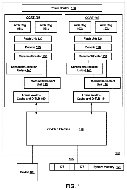
A method and apparatus of a device that rate-limits the execution of a timer is described.
US 9,904,589 B1 · Assignee: AMAZON TECHNOLOGIES, INC. · Inventors: Donlan; Bryan James et al.
Sheet 1 of 47 from the published document. All sheets in the USPTO PDF
Techniques for incrementally increasing media size in data storage systems using grid encoded data storage techniques are described herein. A grid of shards is created where each shard of the grid of shards has a first index, a second index and each shard also has an associated storage device configured with a storage capacity that is large enough to store the largest set of data on a shard. Upon determining to replace the storage devices of the grid with storage devices that have a different storage capacity, the storage devices can be incrementally replaced within the grid by first padding each shard of the grid of shards with a set of data values, replacing a data shard storage device with a device of the different storage capacity, and replacing a set of derived shard storage devices with devices of the different storage capacity.
1 of 47 drawing sheets so far from the published document, cropped to the drawing. Every sheet is in the USPTO PDF.
What the patent claimed, word for word. All of it is now free to use.
This application incorporates by reference for all purposes the full disclosure of co-pending U.S. patent application Ser. No. 14/789,783, filed concurrently herewith, entitled “GRID ENCODED DATA STORAGE SYSTEMS FOR EFFICIENT DATA REPAIR,” co-pending U.S. patent application Ser. No. 14/789,789, filed concurrently herewith, entitled “CROSS-DATACENTER EXTENSION OF GRID ENCODED DATA STORAGE SYSTEMS,” co-pending U.S. patent application Ser. No. 14/789,799, filed concurrently herewith, entitled “CROSS-DATACENTER VALIDATION OF GRID ENCODED DATA STORAGE SYSTEMS,” co-pending U.S. patent application Ser. No. 14/789,810, filed concurrently herewith, entitled “INCREMENTAL UPDATES OF GRID ENCODED DATA STORAGE SYSTEMS,” co-pending U.S. patent application Ser. No. 14/789,815, filed concurrently herewith, entitled “NON-PARITY IN GRID ENCODED DATA STORAGE SYSTEMS,” co-pending U.S. patent application Ser. No. 14/789,825, filed concurrently herewith, entitled “REBUNDLING GRID ENCODED DATA STORAGE SYSTEMS,” and co-pending U.S. patent application Ser. No. 14/789,837, filed concurrently herewith, entitled “DETERMINING DATA REDUNDANCY IN GRID ENCODED DATA STORAGE SYSTEMS.” BACKGROUND
Modern computer systems make extensive use of network computing and network data storage systems. Such use has proliferated in recent years, particularly in distributed or virtualized computer systems where multiple computer systems may share the performance of the tasks associated with the computer system. Such computer systems frequently utilize distributed data storage in multiple locations to store shared data items so that such data items may be made available to a plurality of consumers. The resources for network computing and network data storage are often provided by computing resource providers who leverage large-scale networks of computers, servers and storage drives to enable customers to host and execute a variety of applications and web services. The usage of network computing and network data storage allows customers to efficiently and to adaptively satisfy their varying computing needs, whereby the computing and data storage resources that may be required by the customers are added or removed from a large pool provided by a computing resource provider as needed.
The proliferation of network computing and network data storage, as well as the attendant increase in the number of entities dependent on network computing and network data storage, has increased the importance of balancing both data availability and data integrity on such network computing and network data storage systems. For example, data archival systems and services may use various types of error correcting and error tolerance schemes to ensure data integrity and the expense of data availability leading to a degraded customer experience due to delays in retrieving the data from the data archive.
Various embodiments in accordance with the present disclosure will be described with reference to the drawings, in which:
FIG. 1 illustrates an example environment where a grid encoded data storage system may be used to store data in accordance with an embodiment;
FIG. 2 illustrates an example diagram of the structure of a grid encoded data storage system in accordance with an embodiment;
FIG. 3 illustrates an example diagram showing an update to data stored in a grid encoded data storage system in accordance with an embodiment;
FIG. 4 illustrates an example process for repairing a grid encoded data storage system in accordance with an embodiment;
FIG. 5 illustrates an example process for updating data in a grid encoded data storage system in accordance with an embodiment;
FIG. 6 illustrates an example diagram showing the composition of a grid encoded data storage system in accordance with an embodiment;
FIG. 7 illustrates an example diagram showing a collection of shards of a grid encoded data storage system in accordance with an embodiment;
FIG. 8 illustrates an example diagram showing the recovery of shards in a grid encoded data storage system in accordance with an embodiment;
FIG. 9 illustrates an example diagram showing the recovery of a datacenter of a grid encoded data storage system in accordance with an embodiment;
FIG. 10 illustrates an example diagram showing the recovery of shards in a grid encoded data storage system in accordance with an embodiment;
FIGS. 11 to 14 illustrate a first example of a repair of a loss of a plurality of shards from a grid encoded data storage system in accordance with an embodiment;
FIGS. 15 and 16 illustrate a second example of repair of a loss of a plurality of shards from a grid encoded data storage system in accordance with an embodiment;
FIG. 17 illustrates an example diagram showing null shards in a grid encoded data storage system in accordance with an embodiment;
FIG. 18 illustrates an example diagram showing the addition of data to a grid encoded data storage system in accordance with an embodiment;
FIG. 19 illustrates an example diagram showing operations associated with a grid encoded data storage system in accordance with an embodiment;
FIG. 20 illustrates an example process for performing an incremental update of a grid encoded data storage system in accordance with an embodiment;
FIG. 21 illustrates an example diagram showing the addition of a datacenter to a grid encoded data storage system in accordance with an embodiment;
FIG. 22 illustrates an example diagram showing the addition of data to a grid encoded data storage system in accordance with an embodiment;
FIG. 23 illustrates an example diagram showing the addition of data to a grid encoded data storage system in accordance with an embodiment;
FIG. 24 illustrates an example process for adding data to a grid encoded data storage system in accordance with an embodiment;
FIG. 25 illustrates an example diagram where the size of a storage volume of a grid encoded data storage system is increased in accordance with an embodiment;
FIG. 26 illustrates an example diagram where the size is increased of a storage volume of a grid encoded data storage system in accordance with an embodiment;
FIG. 27 illustrates an example diagram where data may be stored in a data volume of increased size in a grid encoded data storage system in accordance with an embodiment;
FIG. 28 illustrates an example diagram where data may be stored in a data volume of increased size in a grid encoded data storage system in accordance with an embodiment;
FIG. 29 illustrates an example process for updating storage devices in a grid encoded data storage system in accordance with an embodiment;
FIG. 30 illustrates an example diagram where data is stored in heterogeneous storage devices of a grid encoded data storage system in accordance with an embodiment;
FIG. 31 illustrates an example diagram where operations are illustrated that are used to validate shards in a grid encoded data storage system in accordance with an embodiment;
FIG. 32 illustrates an example diagram where operations are illustrated that are used to validate shards in a grid encoded data storage system in accordance with an embodiment;
FIG. 33 illustrates an example environment where data is validated across multiple datacenters of a grid encoded data storage system in accordance with an embodiment;
FIG. 34 illustrates an example process for validating data across multiple datacenters of a grid encoded data storage system in accordance with an embodiment;
FIG. 35 illustrates an example diagram where data is validated across multiple datacenters using different methods in a grid encoded data storage system in accordance with an embodiment;
FIG. 36 illustrates an example diagram of a non-parity grid encoded data storage system in accordance with an embodiment;
FIG. 37 illustrates an example diagram where data of a non-parity grid encoded data storage system is validated in accordance with an embodiment;
FIG. 38 illustrates an example diagram where data is rebundled in a non-parity grid encoded data storage system in accordance with an embodiment;
FIG. 39 illustrates an example diagram where data is rebundled in a non-parity grid encoded data storage system in accordance with an embodiment;
FIG. 40 illustrates an example process for rebundling data in a non-parity grid encoded data storage system in accordance with an embodiment;
FIG. 41 illustrates an example diagram where data sets are partitioned using a grid encoded data storage system in accordance with an embodiment;
FIG. 42 illustrates an example diagram where data sets are partitioned using a grid encoded data storage system in accordance with an embodiment;
FIG. 43 illustrates an example process for partitioning data sets using a grid encoded data storage system in accordance with an embodiment;
FIG. 44 illustrates an example environment where data may be stored in a grid encoded data storage system in accordance with an embodiment;
FIG. 45 illustrates an example process for processing, indexing, storing, and retrieving data of a grid encoded data storage system in accordance with an embodiment;
FIG. 46 illustrates an example of a data storage service in accordance with an embodiment; and
FIG. 47 illustrates an environment in which various embodiments can be implemented.
In the following description, various embodiments will be described. For purposes of explanation, specific configurations and details are set forth in order to provide a thorough understanding of the embodiments. However, it will also be apparent to one skilled in the art that the embodiments may be practiced without the specific details. Furthermore, well-known features may be omitted or simplified in order not to obscure the embodiment being described.
Techniques described and suggested herein include methods, systems, and processes for storing original data of data archives on data storage systems using grid encoding techniques. Grid encoding techniques may be applied to data archives of a computing resource service provider by implementing the storage techniques described herein to increase, for example, availability, redundancy, and durability while minimizing the number of extra storage volume required. In many grid encoding techniques, the stretch factor (i.e., the number of storage volumes required store a volume's worth of data) can approach theoretical minimums as is detailed further herein. Application of such grid encoding techniques allows the storage of original data of the individual archives and redundant storage in other archives, while providing ways to recover from extensive loss of many storage devices and even the recovery of data after the loss of entire data storage facilities.
Data items, which may also be referred to herein as “data archives,” “data objects,” or more simply as “data,” may be received from customers of a computing resource service provider for storage using a grid storage service. Data archives may be received from an archival storage service. Data archives may also be received from other services provided by the computing resource service provider including, but not limited to, redundant storage services, block storage services, virtual machine services, or other such services.
Using a grid encoding technique, data items stored within the grid may be grouped into a collection of shards where each shard represents a logical distribution of the data items stored in the grid. A shard, as used herein, is a logical representation of a set of data stored in the grid and while, in some embodiments, a grid of shards is a partitioning of the data stored in the grid (i.e., each shard is a disjoint set of data items), in other embodiments, shards contain data items that are also stored in other shards. Shards may have an associated set data and/or metadata associated with the shard and/or the grid (e.g., the row and column index of the shard within the grid). Unless otherwise stated or made clear from context, the data items that are represented by the shard and stored in the grid are referred to herein as “shard data” and the data and/or metadata associated with the shard and/or the grid are referred to herein as “shard metadata.”
Each shard may have an associated data storage device and/or an associated data storage volume. A collection of shards may include one or more data shards (e.g., shards associated with data in the data archives), one or more derived shards (e.g., shards associated with grid encoded data associated with the data in the data archives), and/or one more null shards (e.g., shards that are empty and/or are not associated with any data). As used herein, the term “shard” may be used to refer to the data storage abstraction of a shard (i.e., the logical storage device), the associated data storage device of the shard (i.e., the physical storage device), and/or the associated data storage volume of the shard. The shards may be stored using a collection of data storage devices including, but not limited to, tape drives, tapes, disk drives (including both solid state drives and spinning drives), removable media, computer memory, flash drives, various magnetic media, and/or other such storage devices. Each data archive may be stored on one or more data storage devices of the collection of data storage devices, including both homogenous and heterogeneous collections of data storage devices such as, for example, sets of tape drives, sets of disk drives, or sets containing both tape drives and disk drives.
A grid of shards may include a plurality of data shards and one or more derived shards. A grid of shards may also include only derived shards, provided those derived shards are consistent with the redundancy encoding scheme of the grid of shards. The derived shards may include a set of corresponding derived shards for each dimension of the grid. For example, in a two-dimensional grid of shards, the corresponding derived shards may include one or more horizontally-derived shards, and one or more vertically-derived shards. In a grid of shards, the quantity of derived shards is at least equal to a minimum number of shards required to implement a grid encoding scheme associated with the collection of shards in each dimension. In a first example, a collection of shards may contain two data shards containing data and one derived shard as required to implement parity encoding in the horizontal dimension and may also include three “rows” with a fourth row of vertically-derived shards as required to implement a parity encoding in the vertical dimension. Such a grid would include six data shards (two in each of the first three rows), three horizontally-derived shards (one in each of the first three rows), and three-vertically-derived shards (in the fourth row). As used herein, a derived shard required in association with a parity encoding, which may be referred to as a parity shard, may be configured to store the “exclusive or” (denoted “XOR” or “s”) of the data stored in the other (e.g., data and/or derived) shards.
In an illustrative example, a first simple sixteen-bit data shard may contain “0010 1011 0110 1011” and a second simple sixteen-bit data shard may contain “0100 1101 0100 1011.” The XOR of these two simple sixteen-bit data shards is “0110 0110 0010 0000” and this XOR value (e.g., the value obtained from XORing the two simple sixteen-bit data shards) may then be stored in a parity shard. As described herein, a parity encoding is a linear redundancy encoding scheme based on XOR operations. With two data shards and a parity shard, one of the three values may be lost, and the lost value can be reconstructed from the XOR of the remaining two values. For example, if the first data shard is designated “A,” the second data shard is designated “B,” and the parity shard is designated “C,” then A⊕B=C, A⊕C=B, and B⊕C=A (i.e., any of the shards can be reconstructed from the other two). Storing the “exclusive or” of the data shards ensures that even parity is maintained over the three shards because, if A⊕B=C, then A⊕B⊕C=0. Single parity shards may also be used with larger quantities of data shards to the same effect, allowing the reconstruction of any single lost data value. An additional property of a shard is that a portion of a shard can be reconstructed from corresponding portions of the other shard. In the illustrative example above, each of the four-bit groups of data in the sixteen bit parity shard may be interpreted as a four-bit parity shard for the corresponding four-bit values in data shard “A” and data shard “B.”
Similar redundancy encoding techniques may be used in other dimensions of the grid or, in some embodiments, more complex redundancy encoding techniques are used. In a more complex example, four data shards may be combined with two corresponding derived shards (for a total of six shards in the collection of shards) to allow the reconstruction of up to two lost shards (also referred to herein as “damaged shards”) where the lost shards may be data shards, they may be derived shards, or they may be one of each. Reconstruction of shards in such an example may require redundancy codes such as, for example, an online code, a Luby transform code, a Reed-Solomon code, a Cauchy Reed-Solomon code, a regenerating code, a maximum distance separable code, a repetition code, a cyclic code, a Hamming code, a Reed-Muller code, a Goppa code, a BCH code, a Golay code, an expander code, a linear block code, a linear erasure code, and/or some other redundancy code.
In some embodiments, the grid is encoded with a linear block code such as those described herein. A linear block code allows vertically-derived shards such as those described herein to be repaired using the horizontal redundancy encoding scheme of the grid. In some embodiments, the grid is encoded with maximum distance separable codes such as those described herein. A maximum distance separable code allows shards to be derived from any sufficiently large subset of the set of shards in the bundle to be used to reproduce any of the other shards. So, for example, in a 6:4 encoding (e.g., four data shards and two derived shards) with a maximum distance separable code, any four of the shards could be used to reproduce a lost and/or damaged shard of the bundle (i.e., either four data shards, three data shards and one derived shard, or two data shards and two derived shards).
A collection of shards may have any arbitrary number of null shards added to the collection of shards without affecting the redundancy code associated with the collection of shards. For example, because a parity encoding is based on the parity of the data shards, and because a null shard (i.e., a shard with all zeros or an empty shard) does not affect that parity, adding a null shard to that set maintains that parity and, inductively, adding an arbitrary number of null shards to the collection of shards also does not affect that parity. The addition of null shards to collections of shards with more complex redundancy codes also does not affect the more complex redundancy code associated with the collection of shards (e.g., Reed-Solomon codes or Cauchy codes) because the application of such codes to additional null shards simply adds null terms to the associated redundancy encoding calculations. This property of a grid holds when, for example, the grid encoding scheme includes one or more linear block codes as described above. Such linear block codes (e.g., parity, Reed-Solomon) may express the encoding operation as a matrix multiplication of the vector of inputs (e.g., the shards in the grid) with a linear encoding matrix (also referred to herein as a “generator matrix”).
Each shard of a collection of shards may also be padded with any arbitrary corresponding number of zero values (i.e., the arbitrary number of zero values corresponding to each shard) without affecting the redundancy encoding associated with the collection of shards when a linear block code is used. It should be noted that when a linear block code is used to do erasure encoding in a grid, the input data stream (i.e., the data objects) is parsed into a stream of symbols (also referred to herein as “slicing”). Symbols at the same offset are then grouped together and the grouped symbols are encoded (using, for example, the linear block code) into a set of output code words. The code can then be made systematic by fixing some set of the code words, decoding them to obtain the input symbols, and then deriving the remaining code words. In some embodiments, the vertical and horizontal linear erasure codes used for a grid encoding scheme must be linear in the same field (as described below) to support such encoding and decoding.
Linear block coding allows appending zeros because such appending is equivalent to fixing a set of code words to be zero, decoding those zero code words to also be a set of zero symbols, and encoding again to obtain a set of zero code words for the remaining code word positions. The padding of a shard with an amount of data (e.g., zero values) may be illustrated using the previously described example of a first simple sixteen-bit data shard that contains “0010 1011 0110 1011” and a second simple sixteen-bit data shard that contains “0100 1101 0100 1011.” The XOR of these two simple sixteen-bit data shards is “0110 0110 0010 0000” as described above. Padding each of the shards with “0000 0000” does not change the redundancy encoding calculation since “0010 1011 0110 1011 0000 0000”⊕“0100 1101 0100 1011 0000 0000” is “0110 0110 0010 0000 0000 0000” (i.e., the result is similarly padded with “0000 0000”). Other properties associated with padding shards with an arbitrary number of zero (or “null”) values are described below.
FIG. 1 illustrates an example environment 100 where a grid encoded data storage system may be used to store data in accordance with an embodiment. A user 102 may connect 106 to one or more services 112 through a computer system client device 104 . The services 112 may be provided by a computing resource service provider 110 . In some embodiments, the computing resource service provider 110 may provide a distributed, virtualized, and/or datacenter environment within which one or more applications, processes, services, virtual machines, and/or other such computer system entities may be executed. In some embodiments, the user 102 may be a person, or may be a process running on one or more remote computer systems, or may be some other computer system entity, user, or process.
The command or commands to connect to the computer system instance may originate from an outside computer system and/or server, or may originate from an entity, user or process on a remote network location, or may originate from an entity, user or process within the computing resource service provider, or may originate from a user of the computer system client device 104 , or may originate as a result of an automatic process, or may originate as a result of a combination of these and/or other such origin entities. In some embodiments, the command or commands to initiate the connection 106 to the computing resource service provider 110 may be sent to the services 112 , without the intervention of the user 102 . The command or commands to initiate the connection 106 to the services 112 may originate from the same origin as the command or commands to connect to the computing resource service provider 110 , or may originate from another computer system and/or server, or may originate from a different entity, user, or process on the same or a different remote network location, or may originate from a different entity, user, or process within the computing resource service provider, or may originate from a different user of a computer system client device 104 , or may originate as a result of a combination of these and/or other such same and/or different entities.
The user 102 may request connection to the computing resource service provider 110 via one or more connections 106 and, in some embodiments, via one or more networks 108 and/or entities associated therewith, such as servers connected to the network, either directly or indirectly. The computer system client device 104 that may request access to the services 112 may include any device that is capable of connecting with a computer system via a network, including at least servers, laptops, mobile devices such as smartphones or tablets, other smart devices such as smart watches, smart televisions, set-top boxes, video game consoles and other such network-enabled smart devices, distributed computer systems and components thereof, abstracted components such as guest computer systems or virtual machines, and/or other types of computing devices and/or components. The network may include, for example, a local network, an internal network, a public network such as the Internet, or other networks such as those listed or described below. The network may also operate in accordance with various protocols such as those listed or described below.
The computing resource service provider 110 may provide access to one or more host machines, as well as provide access to one or more virtual machine (VM) instances as may be operating thereon. The services 112 provided by the computing resource service provider 110 may also be implemented as and/or may utilize one or more VM instances as may be operating on the host machines. For example, the computing resource service provider 110 may provide a variety of services to the user 102 and the user 102 may communicate with the computing resource service provider 110 via an interface such as a web services interface or any other type of interface. While the example environment illustrated in FIG. 1 shows a single connection or interface for the services 112 of the computing resource service provider 110 , each of the services may have its own interface and, generally, subsets of the services may have corresponding interfaces in addition to or as an alternative to the single interface.
The computing resource service provider 110 may provide various services 112 to its users or customers. The services provided by the computing resource service provider 110 may include, but may not be limited to, virtual computer system services, block-level data storage services, cryptography services, on-demand data storage services, notification services, authentication services, policy management services, or other services. Not all embodiments described may include all of these services, and additional services may be provided in addition to or as an alternative to the services explicitly described. As described above, each of the services 112 may include one or more web service interfaces that enable the user 102 to submit appropriately configured API requests to the various services through web service requests. In addition, each of the services 112 may include one or more service interfaces that enable the services to access each other (e.g., to enable a virtual machine instance provided by the virtual computer system service to store data in or retrieve data from an on-demand data storage service and/or to access one or more block-level data storage devices provided by a block-level data storage service).
The user 102 and/or the device 104 may provide data 114 to the computing resource service provider 110 using the connection 106 and/or the network 108 . The data 114 may be provided to the services 112 , which may in turn provide the data 114 to a grid storage service 116 for storage, which may be one of the services provided by the computing resource service provider 110 . The services 112 may perform operations to, for example, compress, encode, encrypt, edit, or otherwise alter the data. For example, one of the services 112 may be a virtual computer system service that may first store the data 114 locally during the execution of a virtual computer system instance provided by the virtual computer system service, and then may provide the data (in, for example, an edited or otherwise altered form) to the grid storage service 116 . The services 112 may also generate the data 114 directly and/or may generate additional data before providing the data to the grid storage service 116 . In some embodiments, the data 114 is provided directly to the grid storage service 116 via the connection 106 and/or the network 108 .
The grid storage service 116 may be one of a plurality of data storage services provided by the computing resource service provider 110 . The grid storage service 116 may be a service operating within a computer system environment, and running on computing system hardware provided by the computing resource service provider 110 . The grid storage service 116 may also be executing on a virtual computing system, may be running as a distributed service on a plurality of computer systems, and/or may be running as multiple instances on a plurality of computer systems and/or in a plurality of geographic locations. In embodiments where the grid storage service operates as a plurality of instances, the grid storage service 116 may be managed by, for example, a service manager configured to manage computing system resources and/or execution. As used herein, unless otherwise stated or clear from context, the term “service” may be understood to be a computer system program, process, client, server, service, application, module, operating system entity, controlling domain, communication node or collection of these and/or other such computer system entities. A “service” may be a client and/or a server and in some embodiments may be configured to send and/or receive communications, data, requests, and/or other such requests from other services within the computer system.
As described above, the grid storage service 116 may instantiate, operate in conjunction with, or be a component of one or more other services provided by the computing resource service provider 110 . In a first example of such interaction with other services provided by computing resource service provider 110 , the grid storage service may be configured to receive data from a block-level data storage service as a result of determining that the data stored in the block-level data storage should be stored with greater durability or redundancy. As used herein, a block-level data storage service may comprise one or more computing resources that collectively operate to store data for a customer or user such as the user 102 , using block-level storage devices, and/or virtualizations thereof. The block-level storage devices of the block-level data storage service may, for instance, be operationally attached to virtual computer systems provided by a virtual computer system service to serve as logical units (e.g., virtual drives) for the computer systems. A block-level storage device may enable the persistent storage of data used/generated by a corresponding virtual computer system where the virtual computer system service may only provide ephemeral data storage. Such data may then be moved from the block-level storage service to the grid storage service 116 for more permanent, redundant, or durable storage using the grid encoding techniques described herein.
In a second example of how a grid storage service 116 may interact with other services provided by computing resource service provider 110 , the grid storage service 116 may be configured to receive data from an on-demand data storage service as a result of determining data redundancy, data durability, or data availability is an issue. As used herein, an on-demand data storage service may be a collection of computing resources configured to synchronously process requests to store and/or access data. The on-demand data storage service may operate using computing resources (e.g., databases) that enable the on-demand data storage service to locate and retrieve data quickly, to allow data to be provided in responses to requests for the data. For example, the on-demand data storage service may maintain stored data in a manner such that, when a request for a data object is retrieved, the data object can be provided (or streaming of the data object can be initiated) in a response to the request. As noted, data stored in the on-demand data storage service may be organized into data objects. The on-demand data storage service may store numerous data objects of varying sizes. The on-demand data storage service may operate as a key value store that associates data objects with identifiers of the data objects that may be used by the customer or user such as the user 102 to retrieve or perform other operations in connection with the data objects stored by the on-demand data storage service. Data stored in an on-demand data storage service, as well as the data objects themselves, may be moved from the on-demand data storage service to the grid storage service 116 for more permanent, redundant, or durable storage using the grid encoding techniques described herein.
In a third example of how a grid storage service 116 may interact with other services provided by computing resource service provider 110 , the grid storage service 116 may be configured to receive data from an archival data storage service again as a result of determinations regarding data redundancy, data durability, or data availability. As used herein, an archival storage service may comprise a collection of computing resources that collectively operate to provide storage for data archiving and backup of customer data. The data may comprise one or more data files that may be combined to form an archive. The archival storage service may be configured to persistently store data that may be infrequently accessed and for which long retrieval times are acceptable to a customer utilizing the archival storage service. A customer may interact with the archival storage service (for example, through appropriately configured API calls made to the archival storage service) to generate one or more archives, upload and retrieve the one or more archives, or monitor the generation, upload or retrieval of the one or more archives. Data stored in an archival data storage service, as well as the data archives themselves, may be moved from the archival data storage service to the grid storage service 116 for more permanent, redundant, or durable storage using the grid encoding techniques described herein. In an embodiment, an archival storage system is implemented using the grid encoded techniques described herein such that, as data is received in the archival data storage service, the data is grid encoded and stored in a grid of shards.
As used herein, a “shard” is a partition of a data set, where the data set can be partitioned using a redundancy code (also referred to herein as an “erasure code”), associated with a redundancy encoding scheme. The partitioned data set represented by the shards in the grid of shards is the data after the data set has been encoded in the grid of shards rather than the underlying or original data of the data set. Some of the shards may be specific portions of the data set and some of the shards may be generated by applying the redundancy code (or erasure code) to specific portions of the data set.
For example, a redundancy encoding scheme such as “3:2 parity” or “6:4 Reed-Solomon,” both of which are described below, has a redundancy code (or erasure code) associated with the redundancy encoding scheme. In the example of “3:2 parity,” the redundancy code is a parity code. In the example of “6:4 Reed-Solomon,” the redundancy code is a Reed-Solomon code. Using the parity redundancy encoding scheme (also referred to herein as a “parity redundancy code”), a derived shard (e.g., a horizontally-derived shard) may be generated from a plurality of data shards. Together the shards form a partition of the data set where the data shards are the specific portions of the data set and the derived shard is generated by applying the parity code to the data shards. It should be noted that, as used herein, the terms “redundancy code” and “redundancy encoding scheme” may be used interchangeably and, unless explicitly stated or made clear from context, may be understood to refer to the redundancy encoding scheme that includes the redundancy code.
The grid storage service 116 may store data such as the data 114 using grid encoding techniques such as those described herein. In the example illustrated in FIG. 1 , the grid storage service 116 stores data such as the data 114 in a plurality of storage devices corresponding to a grid of shards, which is described in more detail below. The plurality of storage devices may include magnetic tape drives and/or the associated magnetic tapes, magnetic disks, optical disks, flash memory, other computer system memory, memory resistors, or other storage devices. The plurality of storage devices may be located in one or more geographical locations such as, for example, one or more datacenters that are located in physically separate locations.
In the example illustrated in FIG. 1 , the grid storage service 116 uses a first connection 118 to a first datacenter 120 , a second connection 122 to a second datacenter, and a third connection 126 to a third datacenter 128 to store data. Although not illustrated in FIG. 1 , the first connection 118 , the second connection 122 , and/or the third connection 126 may be over a public or private network such as the network 108 described herein.
Data stored in the plurality of storage locations may be redundantly stored using grid encoding techniques such as those described herein. For example, the grid storage service 116 may store data such as the data 114 in a first data storage device 130 in the first datacenter 120 . It should be noted that a data storage device such as the first data storage device 130 may also be referred to herein as a “data storage location,” a “data shard,” a “shard,” a “storage location,” or a “storage device.” When a data storage device is referred to herein as a “data shard” or more simply as a “shard,” it may be understood to refer to a data storage device that corresponds to, or is associated with the shard as described below and may also be understood to refer to the data storage location (i.e., the location of the storage device). As an illustrative example of such usage, a data storage device that is, for example, a magnetic tape, which is located in a datacenter (the data storage location), and which is associated with data shard such as those described below, may be referred to simply as a shard or as a data shard. As used herein and in some examples and descriptions, distinctions between devices, shards, and locations will be explicitly stated unless otherwise made clear from context.
The description continues in the full USPTO document.
About 6,325 words. The USPTO PDF has it with every drawing.
Fees are due 3.5, 7.5 and 11.5 years after grant. This patent expired on February 27, 2026, so the fee marked "not paid" was the one that went unpaid.
Incremental media size extension for grid encoded data storage systems
Filed Jul 2015 · granted Feb 2018Earlier publications, parents and continuations. None of them can still be enforced, or this patent would not be listed.
Prior art cited by the examiner or applicant. Useful when you check your own idea for novelty.
Everything on this page comes from the documents linked above.