Lapsed, fee not paid4 drawings
Software & Apps · US 9,904,564 B2
Policy enforcement by hypervisor paravirtualized ring copying
Methods and systems for executing a request between a virtual machine and a paravirtualized machine are provided.
US 9,904,575 B2 · Assignee: Apple Inc. · Inventors: Kumar; Derek R.
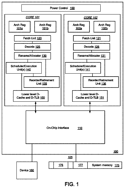
Sheet 1 of 11 from the published document. All sheets in the USPTO PDF
A method and apparatus of a device that rate-limits the execution of a timer is described. The device receives a timer that includes an initial execution timer and a timer priority. If the timer priority is low, the device rate-limits the execution of the timer based on a suppression period associated with the timer priority. In order to rate-limit the execution of the timer, the device determines the suppression period based on the timer priority and schedules the timer to execute at the end of the suppression period. The device further schedules the timer to execute at the initial exertion time when the timer priority is high.
An operating system is a collection of software that manages device hardware resources and provides common services for computer programs. The operating system is a vital component of the system software in a device. Application programs usually require an operating system to function. Interrupts are part of an operating system, as the interrupt provides for the operating system to interact with and react to its environment. When an interrupt is received, the device suspends the program(s) that are currently executing, saves the status of each program, and runs computer code associated with the interrupt. In a modern operating system, the kernel of the operating system handles interrupts. Interrupts may come from either the device's hardware or from a running program. A processor idle state is a low power mode for a computing device that contains at least one processor. When a computing
1 of 11 drawing sheets so far from the published document, cropped to the drawing. Every sheet is in the USPTO PDF.
What the patent claimed, word for word. All of it is now free to use.
This invention relates generally to operating systems and more particularly to devices for timer management.
An operating system is a collection of software that manages device hardware resources and provides common services for computer programs. The operating system is a vital component of the system software in a device. Application programs usually require an operating system to function.
Interrupts are part of an operating system, as the interrupt provides for the operating system to interact with and react to its environment. When an interrupt is received, the device suspends the program(s) that are currently executing, saves the status of each program, and runs computer code associated with the interrupt. In a modern operating system, the kernel of the operating system handles interrupts. Interrupts may come from either the device's hardware or from a running program.
A processor idle state is a low power mode for a computing device that contains at least one processor. When a computing device enters the processor idle state, the processor clock is inactive so that the processor cannot execute instructions, and at least parts of the processor are powered down. This enables the computing device to operate at a reduced power level.
The operating system uses a time-driven interrupt, called a timer, to trigger periodic activity. Each timer generates an interrupt that is handled by the operating system. The number of interrupts generated by the operating system generally increases as the device runs more application programs and as these application programs utilize more device hardware resources. Consequently, the device will be interrupted more frequently and have fewer opportunities to enter or remain in a sleep mode, a processor idle state, or another low power mode. Accordingly, techniques for allowing a device to remain in a low power mode for longer periods of time in order to reduce power consumption while still providing timers are desirable.
A method and apparatus of a device that coalesces the execution of multiple timers by scheduling the timers using a scheduling window is described. In an exemplary embodiment, the device receives multiple timers, where each of the timers includes an initial execution time and a latency time. The device further determines a scheduling window for each of the timers based on the initial execution time and the latency time for that timer. The device selects a coalesced execution time that is within the scheduling window of one or more of the timers. The device further coalesces the execution of the multiple timers by scheduling each of the timers to execute at the coalesced execution time.
In a further embodiment, a method and apparatus of a device that coalesces multiple timers by opportunistic execution of these timers is described. The device detects an opportunistic execution trigger event. In response to the detection of the opportunistic execution trigger event, the device receives multiple timers, where each of the timers includes an initial execution time and a latency time. The device further selects a subset of the timers to execute based on the initial execution time for each of the timers, the latency time for each of the timers, and the opportunistic execution trigger event. The device additionally coalesces the execution of the subset of timers by scheduling each of the subset of timers to execute in response to a detection of the opportunistic execution trigger event.
In one embodiment, each of the received timers is a software timer. In one embodiment, each timer further includes a timer priority. The device further determines the latency time for one of the timers based on the timer priority of that timer. In one embodiment, each timer is associated with a task and the timer priority for each timer is based on the task priority of the associated task. In one embodiment, the latency time of a timer is the amount of time that the execution of that timer can be delayed.
In another embodiment, a method and apparatus of a device that rate-limits the execution of a timer is described. The device receives a timer that includes an initial execution timer and a timer priority. If the timer priority is low, the device rate-limits the execution of the timer based on a suppression period associated with the timer priority. In one embodiment, in order to rate-limit the execution of the timer, the device determines the suppression period based on the timer priority and schedules the timer to execute at the end of the suppression period. In one embodiment, different suppression periods are associated with different timer priorities. In addition, the device schedules the timer to execute at the initial exertion time when the timer priority is high.
Other methods and apparatuses are also described.
The present invention is illustrated by way of example and not limitation in the figures of the accompanying drawings in which like references indicate similar elements.
FIG. 1 is a block diagram of one embodiment of a device that coalesces and rate-limits the execution of timers.
FIG. 2 (prior art) illustrates an approach for executing timers.
FIG. 3 illustrates in one embodiment coalescing timers by scheduling the timers using a scheduling window.
FIG. 4 illustrates a flowchart of one embodiment of a process to coalesce timers based on scheduling windows of the timers.
FIG. 5 illustrates in one embodiment coalescing timers by opportunistic execution of timers in response to an opportunistic execution trigger event.
FIG. 6 illustrates a flowchart of one embodiment of a process to coalesce timers by opportunistic execution of the timers in response to detecting an opportunistic execution trigger event.
FIGS. 7A and 7B illustrate in one embodiment rate-limiting the execution of timers.
FIG. 8 illustrates a flowchart of one embodiment of a process to rate-limit the execution of a timer.
FIG. 9 is a block diagram of the timer management module of one embodiment.
FIG. 10 illustrates one example of a data processing system, which may be used with one embodiment of the present invention.
FIG. 11 illustrates one example of another data processing system, which may be used with one embodiment of the present invention.
A method and apparatus of a device that coalesces and rate-limits the execution of timers is described. In the following description, numerous specific details are set forth to provide thorough explanation of embodiments of the present invention. It will be apparent, however, to one skilled in the art, that embodiments of the present invention may be practiced without these specific details. In other instances, well-known components, structures, and techniques have not been shown in detail in order not to obscure the understanding of this description.
Reference in the specification to “one embodiment” or “an embodiment” means that a particular feature, structure, or characteristic described in connection with the embodiment can be included in at least one embodiment of the invention. The appearances of the phrase “in one embodiment” in various places in the specification do not necessarily all refer to the same embodiment.
In the following description and claims, the terms “coupled” and “connected,” along with their derivatives, may be used. It should be understood that these terms are not intended as synonyms for each other. “Coupled” is used to indicate that two or more elements, which may or may not be in direct physical or electrical contact with each other, co-operate or interact with each other. “Connected” is used to indicate the establishment of communication between two or more elements that are coupled with each other.
The processes depicted in the figures that follow, are performed by processing logic that comprises hardware (e.g., circuitry, dedicated logic, etc.), software (such as is run on a general-purpose device or a dedicated machine), or a combination of both. Although the processes are described below in terms of some sequential operations, it should be appreciated that some of the operations described may be performed in different order. Moreover, some operations may be performed in parallel rather than sequentially.
The terms “server,” “client,” and “device” are intended to refer generally to data processing systems rather than specifically to a particular form factor for the server, client, and/or device.
A method and apparatus of a device that manages the execution of timers in order to reduce power consumption of the device is described. In one embodiment, a timer execution can cause an interrupt on the device. Frequent interrupts can further keep the device from entering or remaining in a low power mode (e.g., processor idle state), which can increase the power consumption of the device. In addition, the operational overhead of the device increases with frequent interrupts and the switching between high and low power modes of the device. In one embodiment, the device coalesces the execution of the timers based on the scheduling windows of the timers in order to reduce the number of interrupts invoked by the timers. In another embodiment, the method and apparatus of a device opportunistically executes timers in response to detecting an opportunistic execution trigger event in order to reduce the number of interrupts invoked by the timers. In yet another embodiment, the method and apparatus of a device rate-limits the execution of the timers so that lower priority timers execute less frequently and invoke less interrupts on the device.
FIG. 1 is a block diagram of one embodiment of a device 100 that coalesces and rate-limits the execution of timers. In one embodiment, the device 100 can be a desktop computer, server, smartphone, laptop, personal digital assistant, music playing device, gaming device, or any other device that can execute multiple processes. In FIG. 1 , device 100 includes an operating system 102 that is a set of software used to manage device hardware resources and provides common services for other running computer programs, such as application programs. The operating system 102 includes a kernel 120 and a timer queue 130 , and manages several tasks 118 .
In one embodiment, the operating system 102 manages several running tasks 118 by scheduling a processor of the device 100 to execute each of the running tasks. The tasks 118 include two categories: high priority tasks 108 and low priority tasks 110 . As illustrated in FIG. 1 , the high priority tasks 108 include user application tasks 104 A and 104 B, and a system task 106 C. The low priority tasks 110 include system tasks 106 A and 106 B, and a user application task 104 C.
In one embodiment, a task is a process that is an instance of a computer program that is being executed. In this embodiment, the task may be a user application that is executing as a result of user input. Another example of a task is a system process that provides one or more services to a user application, another system process, other process, etc. For example, in one embodiment, a system process gives a status of wireless hotspot service, lists installed applications, facilitates a search, monitors and adjusts device power settings, etc. In another embodiment, a task is a thread that is the smallest sequence of programmed instructions that can be managed independently by an operating system scheduler. In one embodiment, a thread is contained inside a process. Multiple threads can exist within the same process and share resources such as memory, while different processes do not share these resources.
In one embodiment, some tasks may have a higher or lower priority than other tasks. A task priority is a property that indicates the urgency with which that task is scheduled to run (or execute) when there are many tasks that need to be run. This task priority is used by the operating system to schedule when a task is to be executed and how fast the task is to be executed. In one embodiment, a task with a higher priority than other tasks would consume a greater amount of the device resources (e.g., processor resources, etc.). In one embodiment, the operating system assigns high task priorities to tasks having high quality of service requirements (e.g., fast service response time) and assigns low task priorities to tasks having low quality of service requirements.
In one embodiment, the priority may be assigned based on a range of numbers from a lowest priority to a highest priority. For example and in one embodiment, a priority range could range from one to ten, 0-127, low/high, or another range of values.
In one embodiment, user application tasks 104 A and 104 B could be running in the foreground, while system tasks 106 A and 106 B running in the background at a priority lower than user application tasks 104 A and 104 B. A task running in the foreground is a task that is interacting with a user or a task performing real-time operations. A task running in the background is a task that is neither interacting with the user nor performing real-time operations. For example and in one embodiment, a user application task 104 A running in the foreground on device 100 may be a user application that is displayed on an output device of the device 100 . In this embodiment, the device 100 can concurrently run one or more system tasks that are not displayed on the device and are instead communicating with other tasks. These system tasks would be executing in the background and not directly visible to the user. In another embodiment, the background tasks may be partially or fully viewable, but are not the focus of the device user interface.
In one embodiment, the priority of a task can be changed during the execution of the task. For example and in one embodiment, if the user application task 104 A running in the foreground requires the service of the system task 106 C, the operating system 102 promotes the system task 106 C to become a high priority task in order to prevent the execution speed of user application task 104 A from being slowed down. For example and in one embodiment, the operating system 102 will promote a system task managing a hard disk of the device to high priority when a user application running in the foreground requires access to the hard disk. In another example and in another embodiment, when a user application task 104 C is no longer interacting with the user or its user interface (UI) is occluded by the UI of another task, the operating system 102 degrades the user application task 104 C to a lower priority task.
In one embodiment, the operating system 102 manages the timer queue 130 . The timer queue 130 is a timer collection. In one embodiment, the timer queue 130 is implemented as a sorted doubly linked list. A person skilled in the art would recognized that the timer queue 130 can be implemented in many different data structures, such as stack, queue, binary tree, hash table, heap, etc.
A timer provides the operating system 102 with a time-driven interrupt source to trigger periodic activity. In one embodiment, a timer is programmed to expire based on the interrupt interval associated with the timer. If the timer is programmed at system time 0 millisecond and has an interrupt time of 10 milliseconds, the kernel 120 would program the timer to expire at system time equals to 10 milliseconds. The timers can be digital counters that either increment or decrement at a fixed frequency, which can be configurable, and interrupt the processor when reaching zero.
In another embodiment, a timer is programmed to expire periodically based on the interrupt interval associated with the timer. If the timer has an interrupt interval of 10 milliseconds, the kernel 120 would program the timer to expire every 10 milliseconds after the timer is set up. This means the timer interrupts the device every 10 milliseconds.
A device interrupt is a signal to the device 100 emitted by hardware or software indicating an event that needs immediate attention. The device 100 responds by suspending its current activities, saving its state, and executing code called an interrupt handler (or interrupt service routine, ISR) to deal with the event. If the device 100 is in the processor idle state, the device 100 will transition itself to a power mode higher than the processor idle state to handle the event. In one embodiment, the device 100 would transition from a processor idle state to a normal operating mode to handle the associated event. A non-timer device interrupt is a device interrupt that is not caused by the firing of a timer (e.g., a hardware interrupt).
The kernel 120 includes a task management module 122 and a timer management module 125 . In FIG. 1 , and in one embodiment, the kernel 120 handles the tasks 118 and the timer queue 130 . In another embodiment, the kernel 120 handles the tasks 118 using the task management module 122 and handles the timer queue 130 using the timer management module 125 .
In another embodiment, the timer management module 125 manages the timer queue 130 and the corresponding timers stored in the timer queue 130 . For example and in one embodiment, the timer management module 125 enqueues and dequeues each timers. In addition, the timer management module 125 schedules the execution time for each timer and executes the timers at their corresponding execution times. The timer management module 125 coalesces and rate-limits the execution of multiple timers in order to keep the device in the low-power mode for longer periods of time, therefore reducing power consumption.
FIG. 2 (prior art) illustrates a timeline 200 for executing timers 202 A-C. Specifically, FIG. 2 illustrates three timers 202 A-C scheduled to execute on a fixed schedule. As shown in the timer attribute table 206 and on the timeline 200 , there are three timers 202 A-C that are scheduled to execute at three different times 204 A-C, respectively. The execution time for each timer is fixed because each of the timers 202 A-C has a fixed time in which this timer expires and the operating system executes the interrupt service handler for the interrupt that corresponds to this timer. In one embodiment, since the execution time of the timers is fixed, the execution of timers 202 A-C will causes three separate interrupts to the device. In this embodiment, if the device enters a low power mode (e.g., processor idle state) in between each timer expiration, the device will wake up three times to deal with these interrupt requests when the device is under the low power mode. These transitions between different operating modes of the device force the device to spend less time under the low power mode and increase the power consumption of the device. Moreover, the frequent switching between different modes increases operating overhead and power consumption of the device.
In order to keep the device in the low power mode for longer periods of time to reduce power consumption, the operating system can manage the execution of the timers to minimize the number of interrupts caused by the timers. FIG. 3 illustrates a timeline 300 for coalescing the timers 302 A-C by scheduling these timers 302 A-C using scheduling windows 308 A-C for each of these timers 302 A-C in one embodiment. In FIG. 3 , these timers 302 A-C can be coalesced by defining a scheduling window 308 A-C for each timer 302 A-C based on a latency time associated with the timer. In one embodiment, a scheduling window defines a time range in which the operating system can delay the execution of the timer. In this embodiment, the scheduling window for each timer 302 A-C is the time range between the scheduled execution time and the scheduled execution time plus the latency time. FIG. 3 identifies several different points of time 304 A-F on the timeline 300 .
As illustrated in the timer attribute table 306 , there are three timers 302 A-C. Each of the timers 302 A-C has a timer priority, an initial execution time, a latency time, and a scheduled execution time. For example and in one embodiment, timer 302 A has a timer priority of 3, an initial execution time of 304 A, a latency time of 1000 milliseconds, and the scheduled execution time is at time 304 C. In this embodiment, the timer 302 A has a scheduling window 308 A that spans from times 304 A to 304 F, which is a time range of 1000 milliseconds. Thus, the operating system can execute the timer 302 A between times 304 A to 304 F.
In one embodiment, the timer priority is the priority assigned to the timer. In one embodiment, the assignment of timer priority is based on the priority of the task that the timer is associated with. For example and in one embodiment, if a timer is associated with a high priority task, a high timer priority will be assigned to this timer. If a timer is associated with a low priority task, a low timer priority will be assigned to this timer. In another embodiment, the assignment of timer priority is not based on the priority of the task that the timer is associated with and instead is based on the operations associated with that timer. For example, a low priority task can start a real-time operation (e.g., playing audio signals) that requires associated timers to have high timer priority. In one embodiment, the higher priority a timer has, the smaller value the operating system assigns to that timer as timer priority. For example, timer 302 C has a timer priority of 1, which is less than the timer priority of timer 302 A. Therefore, timer 302 C has a higher priority than timer 302 A.
The initial execution time is the time when the timer management module initially schedules the timer to execute. However, instead of having a fixed execution time for each timer, the timer management module allows the execution of each time to be delayed for up to a latency time that starts to run at the initial execution time. Therefore, the timer management module can execute a timer at any time between the initial execution time and the initial execution time plus the latency time. The time range between the initial execution time and the end of the latency time is called a scheduling window for the timer. For example, timer 302 B has an initial execution time at 304 B and a latency time of 500 milliseconds. The latency time of timer 302 B starts at 304 B, lasts for 500 milliseconds, and ends at 304 E. Therefore, the time period between 304 B and 304 E is the scheduling window 308 B for the timer 302 B. Similarly, the time period between 304 A and 304 F is the scheduling window 308 A for the timer 302 A, the time period between 304 C and 304 D is the scheduling window for the timer 302 C.
In one embodiment, the operating system determines the length of the latency time based on the timer priority. The higher priority the timer has, the shorter latency time is assigned to the timer. For example, because the timer 302 C has a higher timer priority than timers 302 A and 302 B, the operating system assigns the timer 302 C a latency time of 100 milliseconds, which is shorter than the latency times of timers 302 A and 302 B. Similarly, the operating system assigns the timer 302 B a latency time of 500 milliseconds, which is shorter than the latency time of the timer 302 A (1000 milliseconds), because the timer 302 B has a higher priority than the timer 302 A.
Because each timer has a scheduling window rather than a fixed execution time, the timer management module is able to select an execution time that is within the scheduling windows of multiple timers and schedule those timers to execute at the same selected execution time. For example and in one embodiment, because time 304 C is within the scheduling windows 308 A-C of timers 302 A-C, the timer management module can select time 304 C as the coalesced execution time 310 and schedule the timers 302 A-C to execute at the coalesced execution time 310 . By coalescing the execution of the timers 302 A-C using the scheduling windows 308 A-C, instead of invoking multiple interrupts, the operating system invoke one interrupt to process those multiple timers. As a result, the device can stay in the low power mode for longer periods of time and power consumption of the device is reduced.
FIG. 4 illustrates a flowchart of one embodiment of a process 400 to coalesce execution of multiple timers based on scheduling windows of the timers. In one embodiment, the timer management module executes process 400 to coalesce timers based on scheduling windows of the timers. In one embodiment, process 400 uses scheduling windows to determine a coalesced execution time for multiple timers. In FIG. 4 , process 400 begins by receiving (at block 405 ) multiple timers, where each of these timers has an initial execution time and a latency time. In one embodiment, the timer management module assigns latency time to each timer based on the priority of the timer, as described above in FIG. 3 .
At block 410 , process 400 determines a scheduling window based on the initial execution time and the latency time for each of the received timers. Different timers have different initial execution time and different latency times. In one embodiment, the scheduling window of some timers overlaps with each other in time. For example and in one embodiment, the scheduling windows of the timers 302 A-C in FIG. 3 overlap with each other for times between 304 C to 304 D, inclusive.
At block 415 , process 400 selects a coalesced execution time that is within the scheduling window of some or all of the timers. In one embodiment, process 400 selects a coalesced execution time that is within the overlapped scheduling windows of some or all of the received timers. For example and in one embodiment, process 400 selects time 304 C of FIG. 3 as the coalesced execution time 310 for timers 302 A-C because the time 304 C is within the overlapped scheduling windows of the timers 302 A-C. Process 400 schedules (at block 420 ) each timer to execute at the coalesced execution time. For example and in one embodiment, process 400 schedules the timers 302 A-C of FIG. 3 to execute at the coalesced execution time 310 . At block 425 , the process executes each timer at the coalesced execution time. Process 400 then ends.
In one embodiment, process 400 may not be able to find an overlapped scheduling window for all the received timers. In this embodiment, process 400 determines the a subset of the received timers that have an overlapped scheduling window and selects a coalesced execution time within the overlapped time period of the subset of timers. Process 400 schedules the timers in this determined subset to be executed at the coalesced execution time. The timers that are not in the determined subset are left for further scheduling. In one embodiment, Process 400 schedules the timers that are not coalesced to execute at the initial execution time. In another embodiment, process 400 can go through another iteration to find a coalesced execution time for timers that have not been coalesced.
One of ordinary skill in the art will recognize that process 400 is a conceptual representation of the operations used to perform timer coalescing. The specific operations of process 400 may not be performed in the exact order shown and described. The specific operations may not be performed in one continuous series of operations, and different specific operations may be performed in different embodiments. Furthermore, process 400 could be implemented using several sub-processes, or as part of a larger macro process.
An opportunistic execution trigger event is an event that triggers the opportunistic execution of timers, such as a non-timer device interrupt or a processor idle state entry. For example and in one embodiment, an opportunistic execution trigger event is a non-timer device interrupt. As described above, the device interrupt is a signal to the device emitted by hardware or software indicating an event that needs immediate attention. The device responds by suspending its current activities, saving its state, and executing a small program called an interrupt handler (e.g., an ISR) to deal with the event. If the device is under the processor idle state, the device will transition itself to a power mode higher than the processor idle state to handle the event. A non-timer device interrupt is a device interrupt that is not caused by the firing of a timer (e.g., a hardware interrupt). Therefore, it would be useful to opportunistically execute pending timers if the device detects a non-timer device interrupt.
In another embodiment, an opportunistic execution trigger event is a processor idle state entry. It would be useful for the device to opportunistically execute pending timers prior to entering into the processor idle state in order to minimize exits from the processor idle state. In one embodiment, the opportunistic execution of the timers happens immediately before the entering into the processor idle state, which means the opportunistic execution of the timers is the last set of operations performed by the processor before entering into the processor idle state. In another embodiment, there are one or more intervening operations between the opportunistic execution of the times and entering the processor idle state.
FIG. 5 illustrates a timeline 500 in one embodiment for coalescing timers by opportunistic execution of timers in response to detecting an opportunistic execution trigger event. FIG. 5 identifies several different points of time 504 A-G on the timeline 500 . As illustrated in the timer attribute table 506 , there are three timers 502 A-C. Each of these timers 502 A-C has a timer priority, an initial execution time, a latency time, and a scheduled execution time. For example, for timer 502 A, the timer priority is 3, the initial execution time is 504 A, the latency time is 1000 milliseconds, and the scheduled execution time is 504 C.
In one embodiment, the timer priority is the priority assigned to the timers and can be based on the priority of the task that the timer is associated with. In another embodiment, the timer priority is not based on the priority of the task that the timer is associated with. In one embodiment, the higher priority a timer has, the smaller value the operating system assigns to that timer as timer priority.
The initial execution time is the time when the timer is initially scheduled to be executed. However, instead of having a fixed execution time for each timer, one embodiment allows each timer to be executed within a scheduling window of the timer. Therefore, a timer can be executed at any time in the timer scheduling window, which is defined by the initial execution time and initial execution time plus the latency time. As shown, the scheduling window 508 A for the timer 502 A is the time period between 504 A and 504 G, the scheduling window 508 B for the timer 502 B is the time period between 504 B and 504 F, the scheduling window 508 C for the timer 502 C is the time period between 504 D and 504 E. In one embodiment, the length of the latency time is determined based on the timer priority. The higher priority the timer has, the shorter the latency time that is assigned to the timer.
Because each timer has a scheduling window to determine the timer execution rather than a fixed execution time, the operating system is able to execute multiple timers when an opportunistic execution trigger event occurs within the scheduling window of these timers. For example and in one embodiment, as illustrated in FIG. 5 , if an opportunistic execution trigger event 510 occurs at the time 504 C, the timer management module can execute timers 502 A and 502 B at the time 504 C because the time 504 C falls within the scheduling windows 508 A and 508 B. In addition, the timer management module does not execute timer 502 C at the time 504 C because the time 504 C does not fall within the scheduling window 508 C of the timer 502 C. By coalescing the execution of the timers 502 A and 502 B in response to detecting the opportunistic execution trigger event 510 , fewer interrupts that will cause the processor to exit from its idle state will be invoked. As a result, the device can stay in the low power mode for longer periods of time and power consumption is reduced.
FIG. 6 illustrates a flowchart of one embodiment of a process 600 to coalesce timers by opportunistic execution of the timers in response to detecting an opportunistic execution trigger event. In one embodiment, the timer management module executes process 600 to execute timers opportunistically based on scheduling windows of the timers. Specifically, FIG. 6 describes a process 600 that selects a subset of timers to execute in response to detecting an opportunistic execution trigger event based on the initial execution time and the latency time for the timers. In FIG. 6 , process 600 begins by detecting (at block 605 ) if an opportunistic execution trigger event has occurred. In one embodiment, this opportunistic execution trigger event is a non-timer device interrupt. In one embodiment, the non-timer device interrupt is a hardware interrupt. For example and in one embodiment, process 600 begins by detecting a key on the keyboard is pressed or a mouse button is clicked. In another embodiment, an opportunistic execution trigger event is a processor idle state entry. In one embodiment, the opportunistic execution of the timers happens immediately before the entering into the processor idle state, which means the opportunistic execution of the timers is the last set of operations performed by the processor before entering into the processor idle state. In another embodiment, there are one or more intervening operations between the opportunistic execution of the times and entering the processor idle state.
At block 610 , process 600 receives one or more timers, where each timer has an initial execution time and a latency time. In one embodiment, the timer management module assigns latency time to each timer based on the priority of the timer. For example, as illustrated in the timer attribute table 506 of FIG. 5 above, the latency time of timer 502 A is longer than the latency time of timer 502 B because timer 502 A has a lower priority than timer 502 B.
At block 615 , process 600 determines a scheduling window based on the initial execution time and the latency time for each received timer. In one embodiment, the scheduling window of a timer is defined as the initial scheduled execution time to the initial scheduled execution time plus the latency time. In this embodiment, different timers can have different initial execution times and different latency times. In one embodiment, the scheduling window of some or all of the timers can overlap with each other in time. For example and in one embodiment, the scheduling windows 508 A-C of timers 502 A-C in FIG. 5 overlaps with each other between times 504 D and 504 E and the scheduling windows 508 A-B overlap between times 504 B through 504 E.
At block 620 , process 600 selects a subset of timers of the received timers, where the detected opportunistic execution trigger event occurs within the scheduling windows of those timers. In one embodiment, process 600 selects a timer if the opportunistic execution trigger event occurs within the scheduling window of that timer. For example, as illustrated in FIG. 5 , process 600 selects timers 502 A and 502 B because the opportunistic execution trigger event 510 occurs within the scheduling windows 508 A and 508 B of timers 502 A and 502 B, respectively. Process 600 schedules (at block 625 ) each timer in the subset to execute in response to the detection of the opportunistic execution trigger event. For example and in one embodiment, process 600 schedules timers 502 A and 502 B of FIG. 5 to execute in response to the detection of the opportunistic execution trigger event 510 . In one embodiment, process 600 schedules (at block 625 ) each timer in the subset to execute during the opportunistic execution trigger event. In another embodiment, process 600 schedules (at block 625 ) each timer in the subset to execute prior to the opportunistic execution trigger event, which means the execution of the subset of timers is the last set of instructions executed by the processor before the occurrence of the opportunistic execution trigger event. At block 630 , process 600 executes each timer in the subset at the scheduled execution time.
One of ordinary skill in the art will recognize that process 600 is a conceptual representation of the operations used to perform timer coalescing. The specific operations of process 600 may not be performed in the exact order shown and described. The specific operations may not be performed in one continuous series of operations, and different specific operations may be performed in different embodiments. Furthermore, process 600 could be implemented using several sub-processes, or as part of a larger macro process.
Applications use timers to make provisions for events that occur later. Coalescing timers and opportunistic execution of timers can reduce the chance of the device being interrupted during the low power mode and can further save device power consumption. In one embodiment, the timer management module can rate-limit one or more timers to lessen the frequency a reoccurring timer is executed. In this embodiment, reducing the overall frequency of timer execution can save power consumption and system resources because less frequent timer executions can cause less frequent interrupts for the device.
In one embodiment, the timer management module rate-limits a timer based on the priority of the timer. In one embodiment, the operating system determines the timer priority of each timer based on the task priority of the task associated with the timer. The operating system assigns a high timer priority to a timer when the timer is associated with a high priority task, and assigns a low timer priority to a timer when the timer is associated with a low priority task. For example, real-time tasks have high priorities; therefore the timer management module may not rate-limits timers associated with real-time tasks. On the contrary, the timer management module may rate-limit timers associated with low priority tasks, such as background applications. For example, if a timer is associated with periodically updating the display of an application window (e.g., an animation for the window), when the application window is occluded by another window, the operating system will give a low priority to the timer and rate-limit the execution of the timer in order to save power consumption and system resources.
The description continues in the full USPTO document.
About 6,534 words. The USPTO PDF has it with every drawing.
Fees are due 3.5, 7.5 and 11.5 years after grant. This patent expired on February 27, 2026, so the fee marked "not paid" was the one that went unpaid.
SYSTEM AND METHOD FOR SELECTIVE TIMER RATE LIMITING
Filed May 2013 · published Nov 2014System and method for selective timer rate limiting
Filed May 2013 · granted Feb 2018Earlier publications, parents and continuations. None of them can still be enforced, or this patent would not be listed.
Prior art cited by the examiner or applicant. Useful when you check your own idea for novelty.
Everything on this page comes from the documents linked above.