Lapsed, fee not paid10 drawings
Telecom & Networks · US 9,871,789 B2
Authentication system, authentication method and service providing system
An authentication system comprising an authentication terminal and an authentication server is provided.
US 9,871,808 B2 · Assignee: Nuance Communications, Inc. · Inventors: Tang; Qian-Yu et al.
Sheet 1 of 8 from the published document. All sheets in the USPTO PDF
The present disclosure is directed towards a system and method for handling rogue data packets. The method may include receiving, using one or more processors, a first data packet having header information associated therewith. The method may further include obtaining, from the header information, sequence number, timestamp and synchronization source identifier information. The method may also include detecting one or more rogue data packets, based upon, at least in part, at least one of the sequence number, timestamp and synchronization source identifier information.
Over years in the areas of telephony, data networking, and telecommunications there has been a network shift from analog to digital, wired to wireless, and a continuous migration of some voice calls from conventional time division multiplexing (TDM) networks to packet based internet protocol (IP) networks. Voice over Internet Protocol (“VoIP”) uses real-time transport protocol (RTP) to provide end-to-end delivery services for data with real-time characteristics, such as interactive audio and video. Every RTP packet has a fixed length RTP header, following by RTP payload. The basic RTP header has twelve bytes of data. Among others, the RTP header contains payload type, sequence number, time-stamp, and synchronization source (SSRC). While the increasing of VoIP applications brings new services and lower costs, it also exacerbates the uncertainty of end-to-end voice quality. Voice transmitt
All 8 drawing sheets from the published document, cropped to the drawing.
What the patent claimed, word for word. All of it is now free to use.
This disclosure relates to communications systems and, more particularly, to a system and method for handling rogue RTP packets in Voice over Internet Protocol (“VoIP”) applications.
Over years in the areas of telephony, data networking, and telecommunications there has been a network shift from analog to digital, wired to wireless, and a continuous migration of some voice calls from conventional time division multiplexing (TDM) networks to packet based internet protocol (IP) networks. Voice over Internet Protocol (“VoIP”) uses real-time transport protocol (RTP) to provide end-to-end delivery services for data with real-time characteristics, such as interactive audio and video. Every RTP packet has a fixed length RTP header, following by RTP payload. The basic RTP header has twelve bytes of data. Among others, the RTP header contains payload type, sequence number, time-stamp, and synchronization source (SSRC).
While the increasing of VoIP applications brings new services and lower costs, it also exacerbates the uncertainty of end-to-end voice quality. Voice transmitted over IP networks is suffering from all kinds of impairments such as delay, packet loss, jitter, disorder, etc. In an IP based telephony network, packets may be lost due to network delay, congestion, or errors, thus causing degradation in voice quality. Packet loss concealment (PLC) algorithms are used to recover from lost packets and to improve the impaired quality, where correctly identifying the timing changes in the incoming RTP packets plays an important role.
One of the challenges in the field of VoIP is that more and more services are introduced over years. One example is the interactive voice response (IVR) technology that allows a computer to interact with humans through the use of speech recognition and dual tone multi-frequency (DTMF) tones input via keypad. In telecommunications, IVR allows users to interact with a service provider's host system via a telephone keypad or by speech recognition, so they can service their own inquiries by following the IVR dialogue. IVR systems can respond with pre-recorded or dynamically generated audio to further direct users on how to proceed. In this way, IVR applications may be used to control almost any function where the interface can be broken down into a series of simple interactions. Different real-time streams with voice, data, tones, and events are combined into RTP packets, which may require dynamically changing the RTP header (e.g., with different SSRC numbers). Such RTP packets, once received by the end users, have to be seamlessly played. Unfortunately, the RTP data header validity algorithm in the original RTP standard does not cover the typical IVR applications with dynamically changing SSRC numbers. This leads to the degradation of speech recognition accuracy due to too many missing packets.
RTP is known to be vulnerable to many types of attacks such as spoofing, hijacking, denial of service, traffic manipulation, eavesdropping, and voice injection. As a result, it may be difficult to design a robust RTP packet processing module to prevent the system from rogue RTP attacking Malicious RTP packets contain wrong and misleading timing information in the sequence number and timestamp. Once locked, they can cause system crashes and un-deterministic system behavior. So, it may be critical for VOIP system stability and reliability to filter out malicious rogue RTP packets once detected.
In one implementation, a computer-implemented method for handling rogue data packets is provided. The method may include receiving, using one or more processors, a first data packet having header information associated therewith. The method may further include obtaining, from the header information, sequence number, timestamp and synchronization source identifier information. The method may also include detecting one or more rogue data packets, based upon, at least in part, at least one of the sequence number, timestamp and synchronization source identifier information.
One or more of the following features may be included. In some embodiments, the method may include determining a change in the synchronization source identifier information based upon, at least in part, a resynchronization counter. The method may further include determining a change in the sequence number based upon, at least in part, a resynchronization counter. In some embodiments, the first data packet may be a real-time transport protocol (“RTP”) data packet. In some embodiments, determining a change in the timestamp may be based upon, at least in part, a resynchronization counter. Detecting may be based upon, at least in part, adaptive timing resynchronization. In some embodiments, the first data packet may be transmitted during a Voice over Internet Protocol (“VoIP”) communication system.
In another implementation, a computer-readable storage medium having stored thereon instructions, which when executed by a processor result in one or more operations for handling rogue data packets is provided. Operations may include receiving, using one or more processors, a first data packet having header information associated therewith and obtaining, from the header information, sequence number, timestamp and synchronization source identifier information. Operations may also include detecting one or more rogue data packets, based upon, at least in part, at least one of the sequence number, timestamp and synchronization source identifier information.
One or more of the following features may be included. In some embodiments, operations may include determining a change in the synchronization source identifier information based upon, at least in part, a resynchronization counter. Operations may further include determining a change in the sequence number based upon, at least in part, a resynchronization counter. In some embodiments, the first data packet may be a real-time transport protocol (“RTP”) data packet. In some embodiments, determining a change in the timestamp may be based upon, at least in part, a resynchronization counter. Detecting may be based upon, at least in part, adaptive timing resynchronization. In some embodiments, the first data packet may be transmitted during a Voice over Internet Protocol (“VoIP”) communication system.
In yet another implementation, a system for handling rogue data packets is provided. The system may include one or more processors configured to receive a first data packet having header information associated therewith. The one or more processors may be further configured to obtain, from the header information, sequence number, timestamp and synchronization source identifier information. The one or more processors may be further configured to detect one or more rogue data packets, based upon, at least in part, at least one of the sequence number, timestamp and synchronization source identifier information.
One or more of the following features may be included. In some embodiments, the one or more processors may be further configured to determine a change in the synchronization source identifier information based upon, at least in part, a resynchronization counter. The one or more processors may be further configured to determine a change in the sequence number based upon, at least in part, a resynchronization counter. In some embodiments, the first data packet may be a real-time transport protocol (“RTP”) data packet. Determining a change in the timestamp may be based upon, at least in part, a resynchronization counter. Detecting is based upon, at least in part, adaptive timing resynchronization.
The details of one or more implementations are set forth in the accompanying drawings and the description below. Other features and advantages will become apparent from the description, the drawings, and the claims.
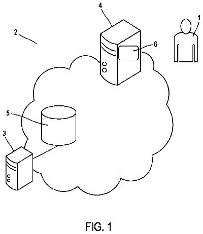
FIG. 1 is a diagrammatic view of a rogue data packet process in accordance with an embodiment of the present disclosure;
FIG. 2 is a flowchart of a rogue data packet process in accordance with an embodiment of the present disclosure;
FIG. 3 is a diagrammatic view of a VoIP model consistent embodiments of the present disclosure;
FIG. 4 is a diagrammatic view of a VoIP model consistent with embodiments of the present disclosure;
FIG. 5 shows an example of a header format consistent with embodiments of the present disclosure;
FIG. 6 is a diagrammatic view of an RTP and jitter buffer module consistent with embodiments of the present disclosure;
FIG. 7 is a diagrammatic view of a voice processing module consistent with embodiments of the present disclosure; and
FIG. 8 shows an example of a computer device and a mobile computer device that can be used to implement embodiments of the present disclosure.
Like reference symbols in the various drawings may indicate like elements.
Embodiments provided herein are directed towards a system and method for handling rogue data packets. In this way, embodiments of the present disclosure relate generally to Voice over Internet Protocol (VoIP) applications in areas that may include, but are not limited to, computer, microprocessor, field programmable gate array (“FPGA”), application specific integrated circuits (ASICs), data networking, telecommunications, and smart phones. Accordingly, embodiments of rogue data packet process 10 may include an RTP packet validation algorithm and a finite state machine, which may be applied to any hardware devices or any software modules.
There are many different kinds of rogue data packets. As used herein, the phrase “rogue data packet” may refer to an RTP data packet having a random RTP header. For example, the payload type, sequence number, time-stamp, and synchronization source (SSRC) identifier in the RTP header could be random. For a typical RTP packet with a 12-byte RTP header, there are a total of 2.sup.96 possibilities for the RTP header. Following the RTP protocol, some of the RTP headers may be classified as invalid and the RTP packet may be discarded (e.g., wrong version number and wrong payload type). In some cases, the rogue RTP packets may be generated by a hostile RTP source (e.g., one having a malicious intent). The rogue RTP packets may also be created by the overlapping of an authentic RTP stream and another unauthentic RTP stream at the same time, which may be caused by the malfunctioning of some networking devices.
Referring to FIG. 1 , there is shown a rogue data packet process 10 that may reside on and may be executed by computer 12 , which may be connected to network 14 (e.g., the Internet or a local area network). Server application 20 may include some or all of the elements of rogue data packet process 10 described herein. Examples of computer 12 may include but are not limited to a single server computer, a series of server computers, a single personal computer, a series of personal computers, a mini computer, a mainframe computer, an electronic mail server, a social network server, a text message server, a photo server, a multiprocessor computer, one or more virtual machines running on a computing cloud, and/or a distributed system. The various components of computer 12 may execute one or more operating systems, examples of which may include but are not limited to: Microsoft Windows Server™; Novell Netware™; Redhat Linux™, Unix, or a custom operating system, for example.
As will be discussed below in greater detail in FIGS. 2-8 , rogue data packet process 10 may include receiving ( 202 ) a first data packet having header information associated therewith. The rogue data packet process may further include obtaining ( 204 ), from the header information, sequence number, timestamp and synchronization source identifier information. The rogue data packet process 10 may also include detecting ( 206 ) one or more rogue data packets, based upon, at least in part, at least one of the sequence number, timestamp and synchronization source identifier information. Rogue data packet process 10 may utilize one or more counters in order to determine changes in the synchronization source identifier information, the sequence number, and the timestamp information associated with a data packet header. Rogue data packet process 10 may also utilize adaptive timing resynchronization techniques as are discussed in further detail hereinbelow.
The instruction sets and subroutines of rogue data packet process 10 , which may be stored on storage device 16 coupled to computer 12 , may be executed by one or more processors (not shown) and one or more memory architectures (not shown) included within computer 12 . Storage device 16 may include but is not limited to: a hard disk drive; a flash drive, a tape drive; an optical drive; a RAID array; a random access memory (RAM); and a read-only memory (ROM).
Network 14 may be connected to one or more secondary networks (e.g., network 18 ), examples of which may include but are not limited to: a local area network; a wide area network; or an intranet, for example.
In some embodiments, rogue data packet process 10 may reside in whole or in part on one or more client devices and, as such, may be accessed and/or activated via client applications 22 , 24 , 26 , 28 . Examples of client applications 22 , 24 , 26 , 28 may include but are not limited to a standard web browser, a customized web browser, or a custom application that can display data to a user. The instruction sets and subroutines of client applications 22 , 24 , 26 , 28 , which may be stored on storage devices 30 , 32 , 34 , 36 (respectively) coupled to client electronic devices 38 , 40 , 42 , 44 (respectively), may be executed by one or more processors (not shown) and one or more memory architectures (not shown) incorporated into client electronic devices 38 , 40 , 42 , 44 (respectively).
Storage devices 30 , 32 , 34 , 36 may include but are not limited to: hard disk drives; flash drives, tape drives; optical drives; RAID arrays; random access memories (RAM); and read-only memories (ROM). Examples of client electronic devices 38 , 40 , 42 , 44 may include, but are not limited to, personal computer 38 , laptop computer 40 , smart phone 42 , television 43 , notebook computer 44 , a server (not shown), a data-enabled, cellular telephone (not shown), and a dedicated network device (not shown).
One or more of client applications 22 , 24 , 26 , 28 may be configured to effectuate some or all of the functionality of rogue data packet process 10 . Accordingly, rogue data packet process 10 may be a purely server-side application, a purely client-side application, or a hybrid server-side/client-side application that is cooperatively executed by one or more of client applications 22 , 24 , 26 , 28 and rogue data packet process 10 .
Client electronic devices 38 , 40 , 42 , 44 may each execute an operating system, examples of which may include but are not limited to Apple iOS™, Microsoft Windows™, Android™, Redhat Linux™, or a custom operating system.
Users 46 , 48 , 50 , 52 may access computer 12 and rogue data packet process 10 directly through network 14 or through secondary network 18 . Further, computer 12 may be connected to network 14 through secondary network 18 , as illustrated with phantom link line 54 . In some embodiments, users may access rogue data packet process 10 through one or more telecommunications network facilities 62 .
The various client electronic devices may be directly or indirectly coupled to network 14 (or network 18 ). For example, personal computer 38 is shown directly coupled to network 14 via a hardwired network connection. Further, notebook computer 44 is shown directly coupled to network 18 via a hardwired network connection. Laptop computer 40 is shown wirelessly coupled to network 14 via wireless communication channel 56 established between laptop computer 40 and wireless access point (i.e., WAP) 58 , which is shown directly coupled to network 14 . WAP 58 may be, for example, an IEEE 802.11a, 802.11b, 802.11g, Wi-Fi, and/or Bluetooth device that is capable of establishing wireless communication channel 56 between laptop computer 40 and WAP 58 . All of the IEEE 802.11x specifications may use Ethernet protocol and carrier sense multiple access with collision avoidance (i.e., CSMA/CA) for path sharing. The various 802.11x specifications may use phase-shift keying (i.e., PSK) modulation or complementary code keying (i.e., CCK) modulation, for example. Bluetooth is a telecommunications industry specification that allows e.g., mobile phones, computers, and smart phones to be interconnected using a short-range wireless connection.
Smart phone 42 is shown wirelessly coupled to network 14 via wireless communication channel 60 established between smart phone 42 and telecommunications network facility 62 , which is shown directly coupled to network 14 .
Referring now to FIG. 3 , a diagram depicting a VoIP model consistent with an embodiment of rogue data packet process 10 is provided. Embodiments of the VOIP platform 300 described herein provide a packet-based network, offering Voice Quality Assurance (VQA), trans-coding, RTP packet processing, jitter buffer for network impairments, etc. FIG. 3 shows one example of a system model of a VOIP platform 300 and the logical position of a Media Processor (MP) 302 within the VOIP platform. It should be emphasized that this is a logical model, which makes no assumptions about the physical locations of the various components (whether they are running on the same hardware, processor, card etc). In some embodiments, media processor 302 may include multiple instantiations of Media Processor Units (MPUs), running on a single or multiple processor cores.
In some embodiments, Application Server 304 may be a hardware device or a software module that may be configured to receive one or more signaling messages, such as the Session Initiation Protocol (SIP) signaling communication messages including the SIP status messages in a typical VOIP application. The Session Description Protocol (SDP) contains the rules that define how multimedia sessions can be set up to allow all end points to effectively participate in the session. The SDP messages may include, but are not limited to, owner and creator IP address and its type, median description such as supported list of codec types and RTP payload type, media attributes such as sampling rate, telephone event payload type, packetization time in terms of milliseconds, etc. In this particular example, the VOIP platform is referred to as “mStage”, where the mStage Application 306 may be configured to support different features and functions. Combined with SIP messages, they may be processed by the media resource manager (MRM) 308 , running on the control path. In some embodiments, MP 302 may be configured to perform some or all operations related to the median payload such as RTP payload. The media application (MA) module 310 may include different components such as VQA algorithms, trans-coding, keyword spotter, tone and events detection and generation, etc.
Referring now to FIG. 4 , a diagram depicting an embodiment of another VoIP model is provided. In this particular example, a VOIP platform model 400 showing the configuration of the physical Media Processing Cards (MPCs) 402 is provided, where up to nine active MPCs may be allocated on media card 404 . Each MPC may have a number of digital signal processors (“DSPs”) 406 with a maximum of 64 DSPs (e.g., TI Janus—C5561 with each DSP consisting of six TMS320C55xx cores running at 300 MHz). Each media card 404 may contain a host processor 408 (e.g., Motorola 8560), which may function as a master for DSPs 406 . In this particular example, each group of 16 DSPs may be connected to an FPGA 410 . The four FPGAs (which may be physically implemented in a single device) are connected to up to 8 Network Processing Units 412 (NPUs) via switch fabric (X) 414 .
As discussed above, in some embodiments the rogue data packet process 10 described herein may be configured to operate upon RTP data packets. RTP is designed to support real time traffic in applications such as voice and video. The RTP header may indicate what type of audio encoding is contained in each packet so that senders can change the encoding during a call.
An example of the RTP fixed header format 500 is shown in FIG. 5 . As depicted in the Figure, a number of fields may be associated with the RTP header. Examples of information that may be included within an RTP header are provided below: Version (V): =2 Padding (P): If the padding bit is set, the packet contains one or more additional padding octets at the end that are not part of the payload. The last octet of the padding contains a count of how many padding octets should be ignored, including itself. Extension (X): If the extension bit is set, the fixed header must be followed by exactly one header extension. CSRC count (CC) The CSRC count contains the number of CSRC identifiers that follow the fixed header Marker (M): To allow significant events such as frame boundaries to be marked in the packet stream. Payload Type (PT): This field identifies the format of the RTP payload and determines its interpretation by the application. Sequence Number: The sequence number increments by one for each RTP data packet sent, and may be used by the receiver to detect packet loss and to restore packet sequence. The initial value of the sequence number should be random. Timestamp: The timestamp reflects the sampling instant of the first octet in the RTP packet. The sampling instant must be derived from a clock that increments monotonically and linearly in time to allow synchronization and jitter calculations. The initial value of the timestamp should be random. Synchronizing source identifier (“SSRC”): The SSRC field identifies the synchronization source. The identifier should be chosen randomly. If a source changes its source transport address, it must choose a new SSRC identifier to avoid being interpreted as a looped source Contributing source identifier (“CSRC”): There can be 0 to 15 items. The CSRC list identifies the contributing sources for the payload contained in this packet.
In some embodiments, rogue data packet process 10 may combine SSRC, timestamp, and sequence number information from the RTP header of each RTP packet into a new RTP packet validation algorithm. Rogue data packet process 10 may use this information to determine whether a rogue data packet exists (e.g., a new state STATE_ROGUE is detected). In this way, rogue data packet process 10 may be used to solve the rogue RTP packet problem, which is a common issue in numerous applications such as VoIP.
Embodiments of rogue data packet process 10 may be used to address various state transitions, for example, where the SSRC number is frequently changed during the middle of a call (e.g. in an interactive voice response “IVR” application during the SSRC verification stage). In this way, packet process 10 may also include the construction and utilization of a new resynchronization counter. When the packet is in sequence, if the resynchronization counter is bigger than zero, the RTP packet state is detected as having a rogue status (e.g. STATE_ROGUE). Additionally and/or alternatively, if the packet is out of sequence, RTP packet state may also be detected as having a rogue status.
In some embodiments, rogue data packet process 10 may be configured to identify a state transition where the sequence number jump is smaller than or equal to a particular value (e.g., RTP_SEQ_MOD−MAX_MISORDER). For example, process 10 may address the scenario where a sequence number has made a very large increase. If the new resynchronization counter is bigger than zero, the RTP packet state is detected as having a rogue status (e.g., STATE_ROGUE).
Additionally and/or alternatively, rogue data packet process 10 may be configured to identify the state transition where the sequence number has a large increase but the sequence number does not equal a bad sequence number. For example, the timestamp value may be used to classify rogue RTP packets among all bad RTP packets having a large sequence number increase as well as a large timestamp increase. Embodiments of data packet process 10 may include an approach for calculating the timestamp difference between the current timestamp value and the previous timestamp value from the RTP state memory. After obtaining the timestamp difference value, if the value is bigger than a particular threshold (e.g., MAX_TS_JUMP=144000, this may indicate an 18 seconds timestamp difference with 8000 Hz sampling frequency), the RTP packet state may also be detected as having a rogue status (e.g. STATE_ROGUE). Embodiments of rogue data packet process 10 may be used to accurately estimate the timestamp changes in the RTP packets, which may be used in other VoIP modules such as jitter buffer (“JB”), packet loss concealment (“PLC”), and acoustic echo cancellation (“AEC”).
An example of a header file (rtp.h) is provided below in the Appendix by way of an example. It should be noted that any portions of code that are included in the present disclosure are included merely by way of example and are not intended to limit the scope of the present disclosure.
In some embodiments, when a call is first established, by using session initiation protocol (“SIP”) signaling messages in a typical VoIP application, the RTP module state memory with data structure RTP_SRC_STATE may be allocated. This RTP module state memory is pointed by a pointer (e.g., RTP_SRC_STATE*pState). The RTP state memory may be initialized by calling a function (e.g., RTPInit(pState)) after the SIP message negotiation stage, i.e., no actual RTP packets show up yet, where the function RTPInit( ) is provided in the Appendix for reference. In this function, the RTP module state variables are initialized (e.g., pState->probation=MIN_SEQUENTIAL; pState->ssrcHP=−1) where a particular number (e.g., MIN_SEQUENTIAL) of sequential packets are required in order to declare a source valid for the newly arrived SSRC identifier. A state variable (e.g., pState->ssrcHP) may be added to represent the number of SSRC changes during the call.
In some embodiments, when the first RTP packet shows up after the SIP signaling negotiation stage, a pointer (e.g., RTP_HEADER*pInputPacket) may be used to point to the RTP header of the RTP packet. The SSRC identifier may be saved for this media stream.
TABLE-US-00001 UINT32 ssrc; ssrc = ((UINT32)pInputPacket−>ssrcHigh)<<16 | pInputPacket−>ssrcLow; if (pState−>ssrc != ssrc) { pState−>ssrcHP++; pState−>ssrc = ssrc; }
By the above convention, if the SSRC number does not change during a call, the SSRC increase (e.g., pState->ssrcHP) may be set to zero after the first RTP packet is received.
In some embodiments, upon the arrival of a new packet, RTP header validity check may be performed according to RFC 3550 Appendix A.1. Embodiments of rogue data packet process 10 may include determining codec type, frame and payload sizes based on packet payload type (e.g., PT field) and packet length. The SSRC, sequence number, and timestamp information may be extracted from the first received packet and used as corresponding base values for outgoing RTP packets. RTP statistics may then be accumulated. In some embodiments, the RTP header may be validated (e.g., using RFC 3550 Appendix A—Algorithms).
Referring now to FIG. 6 , a diagram depicting an RTP and jitter buffer module consistent with rogue data packet process 10 is provided. In this particular example, jitter buffer (JB) 602 may receive speech frames from RTP processor 604 where RTP packets are broken down into speech frames.
Referring also to FIG. 7 , a diagram depicting a voice enhancement device 700 offering Voice Quality Assurance (VQA) with both an RTP module and a JB module is provided. In this particular example, after JB module, the voice frames may be decoded using a speech decoder depending on the codec type used in the RTP packet. The decoded speech data may be processed by the VQA module for voice enhancement, which may also include packet loss concealment (PLC) algorithms. Then, a speech codec may be used to encode the voice enhanced data. The type of speech codec used for speech encoding may be specified by the SIP signaling messages. When a sufficient amount of data is encoded, the RTP packet may be composed and sent out by the RTP packetization module.
Embodiments of rogue data packet process 10 may utilize a finite state machine, which is described in further detail herein below. In some embodiments, an RTP packet validation algorithm may be called for each RTP packet. There are four possible states defined in this function (e.g., STATE_BAD, STATE_GOOD, STATE_RESYNCH, and STATE_ROGUE). STATE_BAD indicates that the validation is failed for the packet, STATE_GOOD indicates that the packet is valid and has passed the validation algorithm, STATE_RESYNCH indicates that the packet contains misleading timing information such as sequence number and timestamp and the packet is in a state for timing resynchronization, and STATE_ROGUE indicates that the packet is in a rogue state, respectively. Existing approaches that handle RTP data packets utilize only the first two states. Embodiments of rogue data packet process 10 may also incorporate a state for timing resynchronization (e.g., STATE_RESYNCH) and a state that identifies that an RTP packet is in a rogue state (e.g., STATE_ROGUE). The algorithm may be implemented using a variety of techniques, for example, via the following function:
TABLE-US-00002 static RTP_PKT_STATES RTPPacketValidate(RTP_SRC_STATE *pState, RTP_HEADER *pPacket)
In the above function, pPacket is a pointer pointing to the current RTP header of the packet and pState is a pointer pointing to the RTP state. By calling this function, the RTP packet may be validated using the sequence number, timestamp, and the SSRC number. In contrast, in existing approaches only the sequence number is validated and the SSRC changes in the middle of a call are not considered. The local variables are defined below:
TABLE-US-00003 UINT16 udelta = pPacket−>seq − pState−>maxSeq; UINT32 uTSdelta, uTScur, uTSpre;
In operation, an example of an RTP packet validation algorithm consistent with embodiments of rogue data packet process 10 is described below. In this particular example, suppose that the probation counter (e.g., pState->probation) is not zero (referred to herein as “case 1 ”). In this case, the new RTP source has not been declared as valid based on the SSRC verification. This may be caused by the SSRC verification at the beginning of the call, or by the SSRC changes in the middle of call (“MoC”), which are described separately.
In this particular example, suppose that the SSRC increase (e.g., pState->ssrcHP) is smaller than one, which means the SSRC verification is performed at the beginning of the call. If the packet is in sequence, then decrease the probation counter (e.g., pState->probation) by one. If the probation counter (e.g., pState->probation) becomes zero, then perform the following operations: i) A function may be called (e.g., RTPInitSequence( )) to initialize the RTP call state; ii) Increase the counter pState->received by one; iii) Finally the function is returned with STATE_GOOD. If the packet is out of sequence, then update the probation counter (e.g., pState->probation) with value (MIN_SEQUENTIAL−1), where MIN_SEQUENTIAL is the minimal number of packets with sequential sequence numbers required for the SSRC validity check. If the function comes here, it is returned with STATE_BAD. In both cases, pState->maxSeq is saved with latest sequence number pPacket->seq. The latest timestamp (pPacket->tsHigh, pPacket->tsLow) is also saved in pState->maxTS.
Using a different example, now consider the opposite scenario to that described above, which means the SSRC verification is performed in the middle of call. In this example, suppose that the packet is in sequence. Rogue RTP packet verification may be performed here. For example, if the resynchonization counter (e.g., pState->rtpResynchCnt) is bigger than zero, the resynchronization counter may be decreased by one. The function is returned with STATE_ROGUE. In the event that resynchronization counter is zero, reset the probation counter (e.g., pState->probation) to zero, call the function RTPInitSequence( ), and increase the counter (e.g. pState->received) by one. As discussed above, pState->received indicates the number of packets received with the same SSRC. Then, the function may be returned with STATE_GOOD.
If the packet is out of sequence, first reset the probation and resynchronization counters (e.g., pState->probation and pState->rtpResynchCnt) to (MIN_SEQUENTIAL−1) and MIN_RESYNCH1 respectively, where MIN_RESYNCH1 is the minimal number of packets with sequential sequence numbers required for the timing resynchronization in order to jump out this rogue RTP state. Then, the function is returned with STATE_ROGUE. In all cases, pState->maxSeq is saved with latest sequence number pPacket->seq. The latest timestamp (pPacket->tsHigh, pPacket->tsLow) is also saved in pState->maxTS.
Using another example, suppose that udelta is smaller than MAX_DROPOUT (referred to herein as “case 2 ”), where udelta is the incremental change of the sequence number compared with previous valid sequence number, and MAX_DROPOUT is the maximum allowed sequence number change in consecutive two packets in order to declare the later packet to be in order, respectively. In order for this situation to occur the situation described in case 1 cannot happen. In this case, the measured sequence number change is small. For a VoIP call to go smoothly, typically this is the situation. The process may check to see if the sequence number is wrapped since it is often a 16-bit variable. If the sequence number (e.g., pPacket->seq) is smaller than the highest sequence number seen (e.g., pState->maxSeq), increase a counter indicating a shifted count of sequence number cycles (e.g., pState->cycles) by one to indicate that the sequence number (e.g., pPacket->seq) wraps around once. Finally, pState->maxSeq may be saved with the latest sequence number pPacket->seq. The latest timestamp (e.g., (pPacket->tsHigh, pPacket->tsLow)) may also be saved in pState->maxTS.
In some embodiments, rogue data packet process 10 may be configured to identify a state transition where the sequence number jump is smaller than or equal to a particular value (e.g., RTP_SEQ_MOD−MAX_MISORDER), where RTP_SEQ_MOD is a guard value (e.g., 0x10000) for a 16-bit integer and MAX_MISORDER is a threshold value to measure the sequence number jump. For example, process 10 may address the scenario where a sequence number has made a very large increase. If the new resynchronization counter equals zero, the RTP packet state is detected as having a resynchronization status (e.g. STATE_RESYNCH).
For example, suppose that udelta is smaller than or equal to (RTP_SEQ_MOD−MAX_MISORDER) (referred to herein as “case 3”). In order for case 3 to occur, cases 1 and 2 cannot occur. First, consider a scenario where the sequence number (e.g., pPacket->seq) equals to the last bad sequence number (e.g., pState->badSeq). The condition indicates that the sequence number has made a very large jump. Rogue RTP packet verification may be performed here. If the resynchronization counter (e.g., pState->rtpResynchCnt) is bigger than zero, the resynchronization counter is decreased by one. The bad sequence number (e.g., pState->badSeq) is set to (pPacket->seq+1) & 0xFFFF. The function is returned with STATE_ROGUE. In the event that the resynchronization counter (e.g., pState->rtpResynchCnt) is zero, call the function RTPInitSequence( ). Then the function may be returned with STATE_RESYNCH, where STATE_RESYNCH indicates that the packet contains misleading timing information and the packet is in a state for timing resynchronization.
In another example, the sequence number (e.g., pPacket->seq) does not equal the last bad sequence number (e.g., pState->badSeq). In this example, the resynchronization counter (e.g., pState->rtpResynchCnt) is set to a configurable value (e.g., MIN_RESYNCH2) and the bad sequence number may be set to a new value having the current sequence number plus 1 using 16-bit precision (e.g., pState->badSeq is set to (pPacket->seq+1) & 0xFFFF). Here, the timestamp value may be used to classify rogue RTP packets among all bad RTP packets having a large sequence number jump as well as a big timestamp jump. Rogue data packet process 10 may read the current timestamp value (e.g., uTScur=[pPacket->tsHigh, pPacket->tsLow]) from the RTP header and then read the previous valid timestamp value (e.g., uTSpre=pState->maxTS) from the RTP state memory. After the wrap-around scenario is considered, the precise timestamp difference may be obtained as discussed below.
In another example, uTScur is bigger than or equal to uTSpre, where uTScur is the current timestamp and uTSpre is the previous valid timestamp. If the difference between uTScur−uTSpre is bigger than or equal to 0x7FFFFFFF, the timestamp has a “wrap around”, where the timestamp overflows and goes back to the beginning because of the nature of fixed-point operations. In this case, the process may calculate the timestamp difference as follows: uTSdelta=((UINT32) 0xFFFFFFFF−uTScur)+uTSpre+1. In the case that there is no timestamp wrap around, calculate the timestamp difference: uTSdelta=uTScur−uTSpre.
In yet another example, uTScur may be smaller than uTSpre. In the case that the difference between uTScur−uTSpre is bigger than or equal to 0x7FFFFFFF, the timestamp has a wrap around. In this case, the process may calculate the timestamp difference as follows: TSdelta=((UINT32) 0xFFFFFFFF−uTScur)+uTSpre+1. In the case that there is no timestamp wrap around, calculate the timestamp difference: uTSdelta=uTScur−uTSpre. After obtaining the timestamp difference value, if uTSdelta is bigger than MAX_TS_JUMP, the function is returned with STATE_ROGUE. Otherwise, the function is returned with STATE_BAD.
In another example, suppose that all conditions in Case 1 , Case 2 , and Case 3 are not satisfied, then the RTP packet is a duplicate or re-ordered packet (referred to herein as “case 4 ”). After the execution of Case 1 to Case 4 , if the function is not returned yet, increase the packet counter received with the same SSRC (e.g., pState->received) by one. After that, the function is returned with state STATE_GOOD. Additional examples of code corresponding to some of these operations may be found in the Appendix.
Embodiments of rogue data packet process 10 may provide adaptive timing resynchronization for rogue RTP data packets. As discussed above, the RTP packet validation algorithm described above may generate one of four states (e.g., STATE_BAD, STATE_GOOD, STATE_RESYNCH, and STATE_ROGUE). The RTP packet state may be obtained by calling this function: rtpPktValidate=RTPPacketValidate(pState,pInputPacket) where pState is the RTP state for this call, pInputPacket is a pointer pointing to the RTP header of current RTP packet, and rtpPktValidate is an instance of RTP_PKT_STATES. In the case that rtpPktValidate equals to STATE_RESYNCH, the jitter buffer (JB) is initialized. In the event that rtpPktValidate is equal to STATE_ROGUE, the current packet is discarded and the packet discard counter (e.g., pState->packetsDiscarded) may be increased by one. At this point, the RTP packet processing function may be returned with an indication that the RTP packet is invalid. If invalid, the RTP packet processing function may be exited. In other cases, the rest of the RTP packet processing continues.
The description continues in the full USPTO document.
About 6,290 words. The USPTO PDF has it with every drawing.
Fees are due 3.5, 7.5 and 11.5 years after grant. This patent expired on January 16, 2026, so the fee marked "not paid" was the one that went unpaid.
SYSTEM AND METHOD FOR HANDLING ROGUE DATA PACKETS
Filed Apr 2014 · published Oct 2015System and method for handling rogue data packets
Filed Apr 2014 · granted Jan 2018Earlier publications, parents and continuations. None of them can still be enforced, or this patent would not be listed.
Prior art cited by the examiner or applicant. Useful when you check your own idea for novelty.
Everything on this page comes from the documents linked above.