Cross reference to related application
This application is a U.S. national stage application of PCT/JP2011/003442 filed on Jun. 16, 2011, the disclosure of which is incorporated by reference.
Technical field
The present invention relates to an air-conditioning apparatus applied, for example, to multi-air-conditioning apparatuses for buildings.
Background
Air-conditioning apparatuses include one in which, like a multi-air-conditioning apparatus for buildings, a heat source (outdoor unit) is installed outside a building and an indoor unit is installed inside the building. A refrigerant that circulates in a refrigerant circuit of the air-conditioning apparatus transfers heat to (or receives heat from) air supplied to a heat exchanger of the indoor unit so as to heat or cool the air. Then, the heated or cooled air is sent to an air-conditioned space for heating or cooling the space.
Such an air-conditioning apparatus often includes a plurality of indoor units, because a building typically has a plurality of indoor spaces. In the case of a large building, a refrigerant pipe that connects the outdoor unit and each indoor unit may reach as long as 100 m. The longer the pipe that connects the outdoor unit and the indoor unit, the larger the amount of refrigerant charged into the refrigerant circuit.
An indoor unit of such a multi-air-conditioning apparatus for buildings is typically installed and used in an indoor space (e.g., office space, room, or shop) where there are people. If for some reason a refrigerant leaks from the indoor unit installed in the indoor space, since the refrigerant may be flammable or toxic depending on its type, the leakage may cause safety or health problems. Even if the refrigerant is harmless to the human body, the leakage of the refrigerant may lower the concentration of oxygen in the indoor space and negatively affect the human body.
As a solution to this, an air-conditioning apparatus may use a secondary loop method in which, for air-conditioning of a space where there are people, a primary-side loop is performed with a refrigerant and a secondary-side loop is performed with harmless water or brine.
For prevention of global warming, there has been a demand for development of air-conditioning apparatuses that use a refrigerant with a low global warming potential (hereinafter may also be referred to as GWP). Promising low GWP refrigerants include R32, HFO1234yf, and HFO1234ze. Adopting only R32 as a refrigerant does not involve significant design changes to the current apparatus and requires only a small development load, because R32 has substantially the same physical properties as R410A which is currently most often used. However, R32 has a GWP of 675, which is a little high. On the other hand, if HFO1234yf or HFO1234ze alone is adopted as a refrigerant, the pressure of the refrigerant is low because of its small density in a low-pressure state (gas state or two-phase gas-liquid state), and thus the loss of pressure increases. However, increasing the diameter (inside diameter) of a refrigerant pipe to reduce the loss of pressure leads to a higher cost.
By using a mixture of R32 and HFO1234yf or HFO1234ze as a refrigerant, it is possible to reduce the GWP while increasing the pressure of the refrigerant. Since R32, HFO1234yf, and HFO1234ze have different boiling points, the resulting refrigerant mixture is a non-azeotropic refrigerant mixture.
It is known that in an air-conditioning apparatus using a non-azeotropic refrigerant mixture, the composition of the refrigerant charged in the apparatus is different from the composition of the refrigerant actually circulating in the refrigeration cycle. This is because the boiling points of the mixed refrigerants are different as described above. The change in refrigerant composition during circulation causes the degree of superheat or subcooling to deviate from the original value, makes it difficult to optimally control the opening degree of an expansion device and various other devices, and leads to degraded performance of the air-conditioning apparatus. To reduce such performance degradation, various refrigerating and air-conditioning apparatuses with means for detecting a refrigerant composition have been proposed (see, e.g., Patent Literatures 1 and 2).
The technique described in Patent Literature 1 includes a bypass that is connected to bypass a compressor, and a double-pipe heat exchanger and a capillary tube are connected to the bypass. A refrigerant composition is calculated on the basis of detection results of various detecting means included in the bypass and a refrigerant composition tentatively set. To determine the refrigerant composition, the technique described in Patent Literature 1 performs repetitive calculations until the calculated refrigerant composition satisfies a condition specified in a control flow.
Like the technique described in Patent Literature 1, the technique described in Patent Literature 2 involves setting a tentative refrigerant composition and calculating a refrigerant composition by repetitive calculations. The technique described in Patent Literature 2 includes a calculation flow for eliminating repetitive calculations.
Patent literature
Patent Literature 1: Japanese Unexamined Patent Application Publication No. 8-75280 (see, e.g., FIG. 8)
Patent Literature 2: Japanese Unexamined Patent Application Publication No. 11-63747 (see, e.g., FIGS. 5 and 9)
In the techniques described in Patent Literatures 1 and 2, where a refrigerant composition is calculated by repetitive calculations, a controller undergoes a heavy calculation load. Also, since the techniques described in Patent Literatures 1 and 2 involve dealing with a large amount of physical property data for the repetitive calculations, a read only memory (ROM) of the controller undergoes a substantial load.
The technique described in Patent Literature 2 has a calculation flow for eliminating the repetitive calculations. However, since some calculations are omitted in the calculation flow, the accuracy of detecting a refrigerant composition may be degraded.
Summary
An object of the present invention is to provide an air-conditioning apparatus that can calculate a refrigerant composition with high accuracy while reducing a calculation load on a controller (computing device) and a load on a ROM.
An air-conditioning apparatus according to the present invention is one that includes a compressor, a first heat exchanger, an expansion device, and a second heat exchanger that are connected by a refrigerant pipe to form a refrigeration cycle, and uses a non-azeotropic refrigerant mixture as a refrigerant for the refrigeration cycle. The air-conditioning apparatus includes a bypass connected to bypass the compressor; a bypass heat exchanger included in the bypass and configured to cool the refrigerant flowing from the compressor into the bypass; a second expansion device included in the bypass and configured to reduce a pressure of the refrigerant flowing out of the bypass heat exchanger; refrigerant state detecting means for detecting a temperature of the refrigerant flowing into the second expansion device, a temperature of the refrigerant flowing out of the second expansion device, and a pressure of the refrigerant sucked into the compressor; and a computing device configured to calculate a composition of the refrigerant circulating in the refrigeration cycle on the basis of a detection result of the refrigerant state detecting means. The computing device calculates a quality of the refrigerant flowing out of the second expansion device on the basis of an inlet liquid enthalpy calculated on the basis of the temperature of the refrigerant flowing into the second expansion device and a saturated gas enthalpy and a saturated liquid enthalpy calculated on the basis of the temperature of the refrigerant flowing out of the second expansion device or the pressure of the refrigerant sucked into the compressor; calculates a liquid-phase concentration and a gas-phase concentration of the refrigerant flowing out of the second expansion device on the basis of the temperature of the refrigerant flowing out of the second expansion device and the pressure of the refrigerant sucked into the compressor; and calculates the composition of the refrigerant circulating in the refrigeration cycle on the basis of the calculated quality, liquid-phase concentration, and gas-phase concentration.
In the air-conditioning apparatus according to the present invention, the computing device calculates a quality of the refrigerant flowing out of the second expansion device on the basis of an inlet liquid enthalpy calculated on the basis of the temperature of the refrigerant flowing into the second expansion device and a saturated gas enthalpy and a saturated liquid enthalpy calculated on the basis of the temperature of the refrigerant flowing out of the second expansion device or the pressure of the refrigerant sucked into the compressor; calculates a liquid-phase concentration and a gas-phase concentration of the refrigerant flowing out of the second expansion device on the basis of the temperature of the refrigerant flowing out of the second expansion device and the pressure of the refrigerant sucked into the compressor; and calculates the composition of the refrigerant circulating in the refrigeration cycle on the basis of the calculated quality, liquid-phase concentration, and gas-phase concentration. It is thus possible to calculate a refrigerant composition with high accuracy while reducing a calculation load on a controller (computing device) and a load on a ROM.
Brief description of drawings
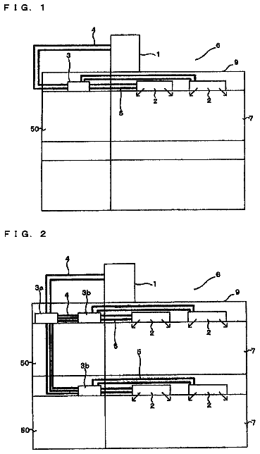
FIG. 1 is a schematic view illustrating an example of installation of an air-conditioning apparatus according to Embodiment of the present invention.
FIG. 2 illustrates a configuration of a refrigerant circuit of the air-conditioning apparatus according to Embodiment of the present invention.
FIG. 3 is an enlarged view of a bypass (composition detecting circuit) of the air-conditioning apparatus illustrated in FIG. 2 .
FIG. 4 is a schematic view of a heat exchanging device illustrated in FIG. 3 .
FIG. 5 is a P-H diagram on which points corresponding to points A to D shown in the bypass illustrated in FIG. 3 are plotted.
FIG. 6 is a flowchart illustrating a control flow for calculating a refrigerant composition used in the air-conditioning apparatus according to Embodiment.
FIG. 7( a ) illustrates a correlation between a saturated liquid temperature and a liquid refrigerant concentration, and a correlation between a saturated gas temperature of a refrigerant and a gas refrigerant concentration, and FIG. 7( b ) illustrates a correlation between a quality and a refrigerant composition.
FIG. 8 is a table for describing to what extent a refrigerant composition set in the control flow for calculating a refrigerant composition gives an error to a calculated refrigerant composition.
FIG. 9 is a table for describing to what extent various detection results in the control flow for calculating a refrigerant composition give an error to a calculated refrigerant composition.
FIG. 10 is a graph for describing to what extent a detection result of an outlet temperature sensor gives an error to a calculated refrigerant composition.
FIG. 11 is a graph for describing to what extent a detection result of an outlet pressure sensor gives an error to a calculated refrigerant composition.
FIG. 12 illustrates a configuration in which an opening and closing device is added to the bypass illustrated in FIG. 3 .
FIG. 13 is a refrigerant circuit diagram illustrating flows of refrigerant in a cooling only operation mode of the air-conditioning apparatus illustrated in FIG. 2 .
FIG. 14 is a refrigerant circuit diagram illustrating flows of refrigerant in a heating only operation mode of the air-conditioning apparatus illustrated in FIG. 2 .
FIG. 15 is a refrigerant circuit diagram illustrating flows of refrigerant in a cooling main operation mode of the air-conditioning apparatus illustrated in FIG. 2 .
FIG. 16 is a refrigerant circuit diagram illustrating flows of refrigerant in a heating main operation mode of the air-conditioning apparatus illustrated in FIG. 2 .
FIG. 17 illustrates a relationship between a quality and a refrigerant composition of R32.
Detailed description
Embodiment of the present invention will now be described with reference to the drawings.
Embodiment
FIG. 1 is a schematic view illustrating an example of installation of an air-conditioning apparatus 100 according to Embodiment of the present invention. The example of installation of the air-conditioning apparatus 100 will be described with reference to FIG. 1 . The air-conditioning apparatus 100 includes a refrigeration cycle for circulating a refrigerant. Each of indoor units 2 a to 2 d can freely select a cooling mode or a heating mode as an operation mode.
The air-conditioning apparatus 100 according to Embodiment includes a refrigerant circuit A (see FIG. 2 ) which uses a non-azeotropic refrigerant mixture as a refrigerant, and a heat medium circuit B which uses water or the like as a heat medium. The air-conditioning apparatus 100 has an improved feature that calculates, with high accuracy, a composition of the refrigerant that circulates in the refrigerant circuit A.
In Embodiment, a non-azeotropic refrigerant mixture composed of R32 and HFO1234yf is used. A low-boiling refrigerant is R32 and a high-boiling refrigerant is HFO1234yf. Unless otherwise specified, a refrigerant composition in Embodiment refers to a composition of R32 which is a low-boiling refrigerant that circulates in the refrigeration cycle. A refrigerant composition of HFO1234yf, which is a high-boiling refrigerant, will not be described, as it is uniquely determined by determining the refrigerant composition of R32.
The air-conditioning apparatus 100 according to Embodiment adopts a method (indirect method) that indirectly uses a refrigerant (heat-source-side refrigerant). Specifically, the air-conditioning apparatus 100 transfers cooling energy or heating energy stored in the heat-source-side refrigerant to a refrigerant (hereinafter referred to as a heat medium) different from the heat-source-side refrigerant, and thereby cools or heats an air-conditioned space with the cooling energy or heating energy stored in the heat medium.
As illustrated in FIG. 1 , the air-conditioning apparatus 100 according to Embodiment includes one outdoor unit 1 serving as a heat source device, a plurality of indoor units 2 , and a heat medium relay unit 3 disposed between the outdoor unit 1 and the indoor units 2 . The heat medium relay unit 3 allows heat exchange between the heat-source-side refrigerant and the heat medium. The outdoor unit 1 and the heat medium relay unit 3 are connected to each other by refrigerant pipes 4 for circulating the heat-source-side refrigerant. The heat medium relay unit 3 and each of the indoor units 2 are connected to each other by pipes (heat medium pipes) 5 for circulating the heat medium. Cooling energy or heating energy generated by the outdoor unit 1 is delivered via the heat medium relay unit 3 to the indoor units 2 .
The outdoor unit 1 is typically placed in an outdoor space 6 which is a space (e.g., rooftop) outside a building 9 . The outdoor unit 1 supplies cooling energy or heating energy via the heat medium relay unit 3 to the indoor units 2 .
The indoor units 2 are each placed at a location from which cooling air or heating air can be supplied to an indoor space 7 which is a space (e.g., room) inside the building 9 . The indoor units 2 supply cooling air or heating air to the indoor space 7 which is to be an air-conditioned space.
The heat medium relay unit 3 is installed in a housing separate from those for the outdoor unit 1 and the indoor units 2 , and is placed at a location different from the outdoor space 6 and the indoor space 7 . The heat medium relay unit 3 is connected via the refrigerant pipes 4 to the outdoor unit 1 , and connected via the pipes 5 to the indoor units 2 . The heat medium relay unit 3 transfers, to the indoor units 2 , cooling energy or heating energy supplied from the outdoor unit 1 .
As illustrated in FIG. 1 , in the air-conditioning apparatus 100 according to Embodiment, the outdoor unit 1 and the heat medium relay unit 3 are connected via two refrigerant pipes 4 , and the heat medium relay unit 3 and each of the indoor units 2 a to 2 d are connected via two pipes 5 . Thus, connecting the different units (outdoor unit 1 , indoor units 2 , and heat medium relay unit 3 ) via the refrigerant pipes 4 and the pipes 5 facilitates construction of the air-conditioning apparatus 100 according to Embodiment.
FIG. 1 illustrates an example where the heat medium relay unit 3 is installed in a space inside the building 9 but not in the indoor space 7 . Specifically, in FIG. 1 , the heat medium relay unit 3 is installed in a space above a ceiling (e.g., a space above the ceiling in the building 9 , hereinafter simply referred to as a space 8 ). The heat medium relay unit 3 may be installed in a shared space, such as a space where there is an elevator. Although the indoor units 2 are of a ceiling cassette type in FIG. 1 , the type of the indoor units 2 is not limited to this. That is, the air-conditioning apparatus 100 may be of a ceiling concealed type, a hanging type, or any other type, as long as heating air or cooling air can be blown either directly or through ducts to the indoor space 7 .
Although the outdoor unit 1 is installed in the outdoor space 6 in FIG. 1 , the location of installation is not limited to this. For example, the outdoor unit 1 may be installed in a confined space, such as a machine room with ventilation openings, or may be installed inside the building 9 as long as waste heat can be discharged through an exhaust duct to the outside of the building 9 . Even when the outdoor unit 1 is a water-cooled unit, the outdoor unit 1 can be installed inside the building 9 . Installing the outdoor unit 1 in such a location causes no particular problems.
The heat medium relay unit 3 may be installed near the outdoor unit 1 . However, it should be noted that if the distance from the heat medium relay unit 3 to the indoor units 2 is too long, the energy-saving effect will be reduced, because a very large amount of power is required to convey the heat medium. The number of different types of units (the outdoor unit 1 , the indoor units 2 , and the heat medium relay unit 3 ) connected to each other is not limited to that illustrated in FIG. 1 , and may be determined, for example, depending on the building 9 where the air-conditioning apparatus 100 is installed.
FIG. 2 illustrates a configuration of a refrigerant circuit of the air-conditioning apparatus 100 according to Embodiment of the present invention. FIG. 3 is an enlarged view of a bypass 50 (composition detecting circuit) of the air-conditioning apparatus 100 illustrated in FIG. 2 . FIG. 4 is a schematic view of a heat exchanging device 51 illustrated in FIG. 3 . A configuration of the air-conditioning apparatus 100 will be described in detail with reference to FIGS. 2 to 4 .
As illustrated in FIG. 2 , the outdoor unit 1 and the heat medium relay unit 3 are connected to each other by the refrigerant pipes 4 via an intermediate heat exchanger 15 a and an intermediate heat exchanger 15 b included in the heat medium relay unit 3 . The heat medium relay unit 3 and the indoor units 2 are connected to each other by the pipes 5 also via the intermediate heat exchanger 15 a and the intermediate heat exchanger 15 b . The refrigerant pipes 4 will be described in detail later on.
[Outdoor Unit 1 ]
The outdoor unit 1 includes a compressor 10 that compresses the refrigerant, a first refrigerant flow switching device 11 formed by a four-way valve or the like, a heat-source-side heat exchanger 12 serving as an evaporator or a condenser, and an accumulator 19 that stores an excess refrigerant. These components of the outdoor unit 1 are connected to the refrigerant pipes 4 .
The outdoor unit 1 is provided with a first connecting pipe 4 a , a second connecting pipe 4 b , a check valve 13 a , a check valve 13 b , a check valve 13 c , and a check valve 13 d . With the first connecting pipe 4 a , the second connecting pipe 4 b , the check valve 13 a , the check valve 13 b , the check valve 13 c , and the check valve 13 d , the flow of the heat-source-side refrigerant into the heat medium relay unit 3 can be regulated in a given direction, regardless of the operation requested by any indoor unit 2 .
As illustrated in FIGS. 2 and 3 , the outdoor unit 1 includes the bypass 50 for detecting (calculating) a refrigerant composition. The bypass 50 includes the heat exchanging device 51 for heat exchange between the refrigerant flowing thereinto from a discharge side of the compressor 10 and the refrigerant flowing into a suction side of the compressor 10 , and an expansion device 52 for reducing a pressure of the refrigerant flowing into the bypass 50 . The bypass 50 includes an inlet temperature sensor 53 that detects a temperature of the refrigerant before it flows into the expansion device 52 , an outlet temperature sensor 54 that detects a temperature of the refrigerant flowing out of the expansion device 52 , and an outlet pressure sensor 55 that detects a pressure of the refrigerant flowing out of the expansion device 52 .
As illustrated in FIG. 2 , the outdoor unit 1 further includes a computing device 57 that calculates a refrigerant composition on the basis of the detection results of the inlet temperature sensor 53 , the outlet temperature sensor 54 , and the outlet pressure sensor 55 .
The compressor 10 sucks in the heat-source-side refrigerant, and compresses the heat-source-side refrigerant into a high-temperature high-pressure state. For example, the compressor 10 may be formed by a capacity-controllable inverter compressor.
The first refrigerant flow switching device 11 switches the flow of the heat-source-side refrigerant between a heating operation mode (a heating only operation mode and a heating main operation mode) and a cooling operation mode (a cooling only operation mode and a cooling main operation mode).
The heat-source-side heat exchanger 12 serves as an evaporator during heating operation, serves as a radiator (gas cooler) during cooling operation, and allows heat exchange between air supplied from an air-sending device such as a fan (not shown) and the heat-source-side refrigerant.
The accumulator 19 is disposed on the suction side of the compressor 10 . The accumulator 19 stores an excess refrigerant produced by a difference between the heating operation mode and the cooling operation mode, and an excess refrigerant produced by a transitional change in operation (e.g., a change in the number of the indoor units 2 in operation) or produced depending on the load condition. In the accumulator 19 , the refrigerant is separated into a liquid-phase refrigerant containing more high-boiling refrigerant and a gas-phase refrigerant containing more low-boiling refrigerant. The liquid-phase refrigerant containing more high-boiling refrigerant is stored in the accumulator 19 . Therefore, when there is a liquid-phase refrigerant in the accumulator 19 , more low-boiling refrigerant tends to be contained in the composition of the refrigerant circulating in the air-conditioning apparatus 100 .
[Refrigerant Composition Detecting Mechanism]
The heat exchanging device 51 (bypass heat exchanger) allows heat exchange between the refrigerant discharged from the compressor 10 and flowing into the bypass 50 , and the refrigerant flowing out of the expansion device 52 and pressure-reduced. That is, the heat exchanging device 51 cools the high-pressure high-temperature refrigerant discharged from the compressor 10 and the flowing into the bypass 50 and turns it into a two-phase gas-liquid refrigerant. For example, the heat exchanging device 51 may use a double-pipe method. Here, the double-pipe method refers to a configuration where, as illustrated in FIG. 4 , a low-pressure two-phase refrigerant flowing out of the expansion device 52 passes through an inside pipe 51 b and a high-temperature gas refrigerant flowing into from the discharge side of the compressor 10 passes through an outside pipe (annular part) 51 a . This can reduce the cost of the heat exchanging device 51 . Note that the heat exchanging device 51 is not limited to this. The heat exchanging device 51 may have a configuration where the pipe 51 a and the pipe 51 b are in contact. A plate heat exchanger, which is expensive, may be used as the heat exchanging device 51 .
The expansion device 52 (second expansion device) reduces the pressure of the refrigerant flowing out of the heat exchanging device 51 and turns it into a low-pressure two-phase gas-liquid refrigerant. The expansion device 52 is connected at one end thereof to the pipe 51 a of the heat exchanging device 51 , and connected at the other end thereof to the pipe 51 b of the heat exchanging device 51 . The expansion device 52 may be formed by a device having a variably controllable opening degree, such as an electronic expansion valve.
The inlet temperature sensor 53 (forming a refrigerant state detecting means) detects a temperature of the refrigerant before it flows into the expansion device 52 . For example, the inlet temperature sensor 53 may be provided in a pipe that connects the pipe 51 a of the heat exchanging device 51 and the expansion device 52 .
The outlet temperature sensor 54 (forming the refrigerant state detecting means) detects a temperature of the refrigerant flowing out of the expansion device 52 . For example, the outlet temperature sensor 54 may be provided in a pipe that connects the expansion device 52 and the pipe 51 b of the heat exchanging device 51 . The inlet temperature sensor 53 and the outlet temperature sensor 54 are connected to the computing device 57 that controls the overall operation of various devices.
The outlet pressure sensor 55 (forming the refrigerant state detecting means) detects a pressure of the refrigerant flowing out of the expansion device 52 . The outlet pressure sensor 55 is described as being provided, for example, in the pipe that connects the expansion device 52 and the pipe 51 b of the heat exchanging device 51 , but the location of the outlet pressure sensor 55 is not limited to this. That is, the outlet pressure sensor 55 may be provided in a pipe extending from a refrigerant discharge side of the expansion device 52 to the suction side of the compressor 10 , or may be provided in a pipe located downstream of the compressor 10 . That is, the outlet pressure sensor 55 may be provided at any location, as long as it can detect a low-pressure refrigerant sucked into the compressor 10 . The pipe located downstream of the compressor 10 refers to, for example, a pipe that connects the first refrigerant flow switching device 11 and the accumulator 19 . The outlet pressure sensor 55 is connected to the computing device 57 that controls the overall operation of various devices.
The computing device 57 calculates a refrigerant composition on the basis of the detection results of the inlet temperature sensor 53 , the outlet temperature sensor 54 , and the outlet pressure sensor 55 . The computing device 57 is connected not only to the inlet temperature sensor 53 , the outlet temperature sensor 54 , and the outlet pressure sensor 55 , but also to a controller (not shown) that controls the overall operation of various devices described below. Thus, on the basis of the refrigerant composition calculated by the computing device 57 , the controller can optimally control, for example, the opening degree of the expansion device 16 described below.
FIG. 2 illustrates an example where the computing device 57 is installed in the outdoor unit 1 which includes the inlet temperature sensor 53 , the outlet temperature sensor 54 , and the outlet pressure sensor 55 . However, the location of the computing device 57 is not limited to this. The computing device 57 may be installed in each indoor unit 2 or in the heat medium relay unit 3 .
In the computing device 57 , a ROM stores a physical property table that shows, for each refrigerant composition value, a correlation between a liquid enthalpy and a refrigerant temperature, a correlation between a saturated liquid enthalpy and a refrigerant temperature, and a correlation between a saturated gas enthalpy and a refrigerant temperature. Also in the computing device 57 , the ROM stores a physical property table that shows, for each refrigerant pressure, a correlation between a saturated liquid temperature of a refrigerant and a liquid refrigerant concentration, and a correlation between a saturated gas temperature of a refrigerant and a gas refrigerant concentration (see FIGS. 7( a ) and 7( b ) ). The physical property tables in the computing device 57 can be set, for example, after installation of the air-conditioning apparatus 100 . Although the physical property tables showing the above-described correlations have been described as being stored in the ROM of the computing device 57 , formulated functions instead of tables may be stored in the ROM.
Various physical quantities calculated by the computing device 57 will now be described.
The computing device 57 can calculate a liquid enthalpy (inlet liquid enthalpy) of the refrigerant flowing into the expansion device 52 on the basis of a physical property table and a detection result of the inlet temperature sensor 53 . On the basis of the physical property table and a detection result of the outlet temperature sensor 54 , the computing device 57 calculates a saturated liquid enthalpy and a saturated gas enthalpy of the refrigerant flowing out of the expansion device 52 .
Although an exact refrigerant composition value is not yet known when the computing device 57 calculates the inlet liquid enthalpy, saturated liquid enthalpy, and saturated gas enthalpy, the computing device 57 sets a tentative refrigerant composition value and calculates them. That is, the computing device 57 calculates the liquid enthalpy on the basis of a physical property table corresponding to the set refrigerant composition value and the detection result of the inlet temperature sensor 53 , and calculates the saturated liquid enthalpy and the saturated gas enthalpy on the basis of the physical property table and the detection result of the outlet temperature sensor 54 . Thus, even when an exact refrigerant composition value is not yet known, the air-conditioning apparatus 100 according to Embodiment can calculate a refrigerant composition with high accuracy, and eliminate the need for repetitive calculations required in the related art. This will be described later on.
On the basis of the physical property table and the detection results of the outlet temperature sensor 54 and the outlet pressure sensor 55 , the computing device 57 can further calculate a concentration of the liquid refrigerant flowing out of the expansion device 52 and a concentration of the gas refrigerant flowing out of the expansion device 52 .
The computing device 57 can calculate a quality on the basis of the calculated inlet liquid enthalpy, saturated liquid enthalpy, and saturated gas enthalpy. The quality is calculated using the following Equation 1:
Xr = Hin - Hls Hgs - Hls [ Equation 1 ]
The computing device 57 calculates a refrigerant composition on the basis of the quality, the concentration of liquid refrigerant, and the concentration of gas refrigerant. The refrigerant composition is calculated using the following Equation 2: α=(1− Xr )× XR 32+ Xr×YR 32 [Equation 2]
[Indoor Units 2 ]
Each of the indoor units 2 includes a use-side heat exchanger 26 . The use-side heat exchanger 26 is connected by the pipes 5 to the corresponding heat medium flow control device 25 and the corresponding second heat medium flow switching device 23 of the heat medium relay unit 3 . The use-side heat exchanger 26 allows heat exchange between air supplied from an air-sending device such as a fan (not shown) and the heat medium, and generates heating air or cooling air to be supplied to the indoor space 7 .
[Heat Medium Relay Unit 3 ]
The heat medium relay unit 3 includes two intermediate heat exchangers 15 for heat exchange between the refrigerant and the heat medium, two expansion devices 16 a and 16 b for reducing the pressure of the refrigerant, two opening and closing devices 17 a and 17 b for opening and closing the passages of the refrigerant pipes 4 , two second refrigerant flow switching devices 18 for switching the refrigerant passages, two pumps 21 for circulating the heat medium, four first heat medium flow switching devices 22 connected to the respective pipes 5 , four second heat medium flow switching devices 23 connected to the other respective pipes 5 , and four heat medium flow control devices 25 connected to the respective pipes 5 to which the first heat medium flow switching devices 22 are connected.
The two intermediate heat exchangers 15 a and 15 b (also referred to as the intermediate heat exchangers 15 ) each serve as a condenser (radiator) or an evaporator, allow heat exchange between the heat-source-side refrigerant and the heat medium, and transfer cooling energy or heating energy generated by the outdoor unit 1 and stored in the heat-source-side refrigerant to the heat medium. The intermediate heat exchanger 15 a is disposed between the expansion device 16 a and a second refrigerant flow switching device 18 a in the refrigerant circuit A, and used for cooling the heat medium in a cooling and heating mixed operation mode. The intermediate heat exchanger 15 b is disposed between the expansion device 16 b and a second refrigerant flow switching device 18 b in the refrigerant circuit A, and used for heating the heat medium in the cooling and heating mixed operation mode.
The two expansion devices 16 a and 16 b (which may also be referred to as the expansion devices 16 ) each serve as a pressure reducing valve or an expansion valve, and reduce the pressure of the heat-source-side refrigerant and expand it. The expansion device 16 a is disposed upstream of the intermediate heat exchanger 15 a in the direction in which the heat-source-side refrigerant flows in the cooling only operation mode. The expansion device 16 b is disposed upstream of the intermediate heat exchanger 15 b in the direction in which the heat-source-side refrigerant flows in the cooling only operation mode. The two expansion devices 16 may each be formed by a device having a variably controllable opening degree, such as an electronic expansion valve.
The opening and closing devices 17 a and 17 b are each formed by a two-way valve or the like, and open and close the corresponding refrigerant pipe 4 .
The two second refrigerant flow switching devices 18 a and 18 b (which may also be referred to as the second refrigerant flow switching devices 18 ) are each formed by a four-way valve or the like, and switch the flow of the heat-source-side refrigerant depending on the operation mode. The second refrigerant flow switching device 18 a is disposed downstream of the intermediate heat exchanger 15 a in the direction in which the heat-source-side refrigerant flows in the cooling only operation mode. The second refrigerant flow switching device 18 b is disposed downstream of the intermediate heat exchanger 15 b in the direction in which the heat-source-side refrigerant flows in the cooling only operation mode.
Two pumps 21 a and 21 b (which may also be referred to as the pumps 21 ) circulate the heat medium in the pipes 5 . The pump 21 a is provided in the pipe 5 between the intermediate heat exchanger 15 a and the corresponding second heat medium flow switching device 23 . The pump 21 b is provided in the pipe 5 between the intermediate heat exchanger 15 b and the corresponding second heat medium flow switching device 23 . The two pumps 21 may be formed, for example, by capacity-controllable pumps. The pump 21 a may be provided in the pipe 5 between the intermediate heat exchanger 15 a and the corresponding first heat medium flow switching device 22 . The pump 21 b may be provided in the pipe 5 between the intermediate heat exchanger 15 b and the corresponding first heat medium flow switching device 22 .
Four first heat medium flow switching devices 22 a to 22 d (which may also be referred to as the first heat medium flow switching devices 22 ) are each formed by a three-way valve or the like, and switch the passage of the heat medium. The number of the first heat medium flow switching devices 22 is determined in accordance with the number of the indoor units 2 installed (which is four here). Each of the first heat medium flow switching devices 22 is connected at one of the three ports thereof to the intermediate heat exchanger 15 a , connected at another of the three ports thereof to the intermediate heat exchanger 15 b , and connected at the remaining one of the three ports thereof to the corresponding heat medium flow control device 25 . The first heat medium flow switching devices 22 are each located on the outlet side of the heat medium passage of the corresponding use-side heat exchanger 26 . In the drawing, the first heat medium flow switching device 22 a , the first heat medium flow switching device 22 b , the first heat medium flow switching device 22 c , and the first heat medium flow switching device 22 d are illustrated, in this order from the bottom of the drawing, to correspond to the respective indoor units 2 .
Four second heat medium flow switching devices 23 a to 23 d (which may also be referred to as the second heat medium flow switching devices 23 ) are each formed by a three-way valve or the like, and switch the passage of the heat medium. The number of the second heat medium flow switching devices 23 is determined in accordance with the number of the indoor units 2 installed (which is four here). Each of the second heat medium flow switching devices 23 is connected at one of the three ports thereof to the intermediate heat exchanger 15 a , connected at another of the three ports thereof to the intermediate heat exchanger 15 b , and connected at the remaining one of the three ports thereof to the corresponding use-side heat exchanger 26 . The second heat medium flow switching devices 23 are each located on the inlet side of the heat medium passage of the corresponding use-side heat exchanger 26 . In the drawing, the second heat medium flow switching device 23 a , the second heat medium flow switching device 23 b , the second heat medium flow switching device 23 c , and the second heat medium flow switching device 23 d are illustrated, in this order from the bottom of the drawing, to correspond to the respective indoor units 2 .
The description continues in the full USPTO document.
 Lapsed, fee not paid3 drawings