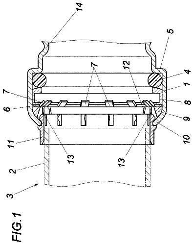
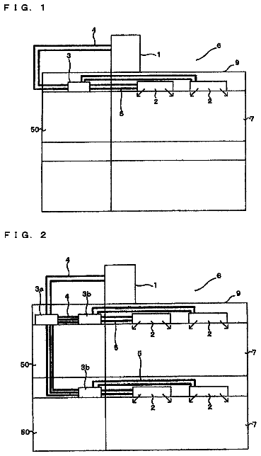
Lapsed, fee not paid12 drawings
Industrial Equipment · US 9,856,999 B2
Corrugated steel pipe and method for manufacturing the same
A corrugated steel pipe is disclosed.
US 9,857,014 B2 · Assignee: Car-Ber Investments Inc. · Inventors: Carson; Glenn et al.
Sheet 1 of 12 from the published document. All sheets in the USPTO PDF
A restraint or gripping device for anchoring within the interior of a pipe comprises a pair of end plates adapted to be urged towards each other and a plurality of shoes, positioned between the end plates, and adapted to be moved radially outwardly as the end plates are urged together. In a further aspect, a method of restraining a pipe plug or isolation tool is provided. Also provided are assemblies for pipe isolation including an integral restraint or gripping mechanism.
1 of 12 drawing sheets so far from the published document, cropped to the drawing. Every sheet is in the USPTO PDF.
What the patent claimed, word for word. All of it is now free to use.
The present invention relates to clamping or restraining devices that are capable of being anchored or clamped within the interior of pipes.
2. Relevant Background
It is common for testing tools to be utilized for testing the integrity of pipes or welds provided on pipes. In addition, various isolation tools are known, which are used to isolate a particular section of a pipe from another. Examples of such tools are provided in U.S. Pat. Nos. 5,844,127 and 6,131,441 (the entire contents of these patents being incorporated herein by reference). In use, tools such as these are inserted within a pipe and anchored against the interior wall of the pipe. With the tools of the aforementioned patents, the anchoring step is achieved by means of bolts and the like that deform resilient annular rings such that the rings deform radially outwardly against the pipe wall. The tools, once positioned and anchored are able to withstand a high degree of displacement pressure.
Notwithstanding the anchoring force provided by the aforementioned tools themselves, it may be advisable to provide, for additional safety, a further clamp or restraint device within the pipe to restrain the tool in the event that pressure is built up adjacent the tool. As will be understood by persons skilled in the art, in situations where the pressure exceeds the anchoring force of the tool, the tool may be violently ejected from the pipe. Thus, a restraint device would offer an additional support in such circumstances.
It is also known in the art to provide internal clamps to maintain two pipes in axial alignment while welding such pipes together. Examples of such internal clamps are provided in U.S. Pat. Nos. 4,463,938; 5,816,475; and 5,875,955 (the entire contents of these patents being incorporated herein by reference). The devices described in these patents comprise complex mechanical mechanisms that are designed to be anchored against the interior walls of adjacent pipes so as to hold such pipes in abutting arrangement. A welding process can then be applied to join the pipe ends together.
Another issue faced with known internal clamping devices is that they often result in damage to the internal wall of the pipe in which they are used. That is, many of the known clamps utilize shoes that are biased against the internal pipe wall and which are provided with teeth to engage such wall. The teeth provide an added anchoring force to prevent translational movement of the device within the pipe. However, as will be understood, once the device is removed, the marks left by such teeth would result in damage to the pipe interior and in some cases lead to a region of weakness.
The devices known in the art comprise either cumbersome and/or complex mechanisms or are not easily adaptable for use with testing or isolation tools or result in damage to the pipe. Thus, there exists a need for an improved internal pipe clamp or restraint device.
The present invention provides an assembly which finds application in closing and sealing the open end of a pipe into which the assembly is inserted. The assembly comprises an isolation tool combined with a restraint device, said tool and device being coupled by threaded assemblies, such as tie rod assemblies, extending axially therethrough. In use, the threaded tie rod assemblies may be tightened to axially compress the isolation tool and actuate the restraint device. When the isolation tool is compressed, its spaced apart pair of annular sealing members are deformed and expand radially to sealably engage the pipe. Preferably the restraint device is concurrently actuated to drive its shoes radially outward into frictional engagement with the pipe wall. In conjunction therewith, the sealing members and pipe interact with the body of the isolation tool to form a sealed space into which pressurized fluid may be introduced for monitoring the sealing members for leakage.
More specifically, in one embodiment an assembly is provided for insertion in the open end of a pipe for the purpose of closing and sealing the pipe's bore, the assembly having upstream and downstream ends and, when in use, comprising: first and second bosses; a body positioned between the bosses said body having a recessed outer annular side surface; first and second resilient, deformable, annular sealing members, each sealing member positioned between one end of the body and a boss; the end surfaces of the body and the adjacent surfaces of the bosses being configured so as to radially deform the sealing members when the bosses and body are urged axially together; a plate positioned downstream of the second boss; the bosses, body and plate being arranged in parallel, spaced apart positions so that they extend transversely of the pipe bore; an annular array of curved, spaced apart shoes positioned between the second boss and the plate, said shoes and plate having oppositely directed beveled edges in contact; and a plurality of tie rods extending axially through the assembly; the body, second boss and plate being slidably mounted on the tie rods; and nuts threadably engaging the tie rods; whereby the nuts may be advanced along the tie rods to axially compress the assembly to thereby deform the sealing members into sealing engagement with the pipe and drive the shoes outwardly and radially into frictional engagement with the pipe, whereby the annular side surface of the body, the inner surface of the pipe and the sealing members combine to form a sealed annular space; the assembly forming port means, extending therethrough its downstream end to the sealed annular space, for introducing pressurized fluid into the space.
In one aspect, the invention provides a restraint device for anchoring within a pipe having an inner diameter, the device comprising: first and second end plates, said end plates being adapted to be coaxially aligned when in use; urging means provided on one or both end plates for urging said end plates together; a plurality of shoes provided between the end plates; the shoes being adapted to be moved radially outwardly as the end plates are urged together.
In another aspect, the invention provides a restraint system comprising one or more of the devices of the invention wherein the one or more devices are positioned within a pipe adjacent to a pipe plug or isolation tool.
In another aspect, the invention provides a method of restraining a pipe plug or isolation tool comprising: securing the pipe plug or isolation too within a pipe at a desired position; and securing a restraint device as described hereinabove within the pipe adjacent to said plug or tool.
In a further aspect, the invention provides an assembly for isolating an internal segment of a pipe, the assembly comprising: a shaft having a first end and a second end; a first boss connected to the first end of the shaft; a sleeve slidably and coaxially provided over the shaft, the sleeve having a first end and a second end, wherein the first end of the sleeve is directed to the first end of the shaft; a second boss secured to the first end of the sleeve; first and second annular bodies provided between the first and second bosses, the first annular body positioned adjacent the first boss and the second annular body positioned adjacent the second boss; a first resilient sealing member positioned between the first boss and the first annular body and a second resilient sealing member positioned between the second boss and the second annular body; a plurality of shoes provided between the first and second annular bodies, the shoes being adapted to be urged radially outwards when the device is in use; a nut, provided at the second end of the shaft for urging the sleeve towards the first end of the shaft.
In another aspect, the invention provides an assembly for isolating an internal segment of a pipe, the assembly comprising: a first boss and a second boss; an annular body provided between the first and second bosses; a first and second resilient sealing members positioned on opposite ends of the annular body and between the respective first or second boss; a plurality of tie rods extending from the first boss towards the second boss, the tie rods being adapted to extend through the inner diameter of the annular body and through a plurality of bolt holes provided on said second boss; a plate provided adjacent the second boss on a side opposite to the annular body, the plate including a plurality of bolt holes through which the tie rods are extendable; a plurality of shoes provided between the second boss and the plate; and, a plurality of first nuts provided for engaging the tie rods on a side of the plate opposite the shoes for urging the plate in a direction towards the first boss.
These and other features of the invention will become more apparent in the following detailed description in which reference is made to the appended drawings wherein:
FIG. 1 is a cross sectional view of a restraint device according to an aspect of the invention positioned within a pipe.
FIG. 2 is an end view of the device of FIG. 1 taken along the line 2 - 2 .
FIG. 3 is a cross sectional view of a restraint device according to an aspect of the invention positioned within a pipe and shown in use with an isolation tool as known in the art.
FIG. 4 is a cross sectional view of two restraint devices of FIG. 1 in tandem use within a pipe.
FIG. 5 is a cross sectional view of a restraint device according to another aspect of the invention positioned within a pipe.
FIG. 6 is an end view of the device of FIG. 5 taken along the line 6 - 6 .
FIG. 7 is a cross sectional view of a restraint device according to an aspect of the invention positioned within a pipe and shown in use with a pipe plug as known in the art.
FIGS. 8 and 9 are partial cross sectional views of another embodiment of the invention incorporating pipe isolation and gripping mechanisms.
FIGS. 10 and 13 are partial cross sectional views of another embodiment of the invention incorporating pipe isolation and gripping mechanisms.
FIG. 11 is an exploded view of the device of FIG. 10 .
FIG. 12 is an end view of the device of FIG. 10 taken along the line 12 - 12 .
FIG. 14 is a partial cross sectional view of another embodiment of the invention incorporating pipe isolation and gripping mechanisms.
FIG. 15 is an exploded view of the device of FIG. 14 .
As used herein, the terms “clamp” or “restraint device” or “restraining device” will be understood to have the same meaning. That is, these terms will be used to refer to the present invention, which is adaptable to be inserted within a pipe and to be frictionally anchoring there-within, against the internal wall of such pipe. The invention will be described with reference to various aspects thereof. It will be understood that a number of modifications of the device will be possible in relation to the size of the device, which, in turn, relates to the size of the pipe in which the device is to be used.
One aspect of the present invention is illustrated in FIG. 1 . As shown, the device 10 of the invention is provided within a pipe 12 . The device 10 is shown in the engaged position wherein the device 10 is anchored against the interior wall of the pipe. The device comprises first and second, generally circular end plates 14 and 16 , respectively. When the device is in use, as shown in FIG. 1 , the end plates 14 and 16 are arranged in coaxial alignment with the longitudinal axis of the pipe 12 . The end plates 14 and 16 have internal faces 18 a and 18 b , respectively, that face each other, and oppositely directed external faces 20 a and 20 b , respectively. The end plates 14 and 16 are provided with outer edges 22 a and 22 b , respectively. The outer edges 22 a and 22 b are generally circular in end view (such as shown in FIG. 2 ). As illustrated in FIG. 1 , the diameter of the internal faces 18 a and 18 b is less than the diameter of the outer faces 20 a and 20 b . This is achieved by providing each of the outer edges 22 a and 22 b with a bevel, 21 a and 21 b , respectively, which extends from or near the external faces 20 a and 20 b towards the internal faces 18 a and 18 b , respectively.
As will be understood, and as shown in FIG. 1 , the end plates 14 and 16 of the device 10 , are sized so as to be slid ably introduced into a pipe 12 to be tested. That is, the maximum diameter of the end plates is less than the inner diameter of the pipe 12 .
The device 10 of the invention further includes a plurality of circumferentially spaced shoes or “gripper plates” 24 . In the embodiment of the invention illustrated in FIGS. 1 and 2 , six such shoes, 24 a to 24 f , are shown. However, it will be understood by persons skilled in the art that any number of such shoes may be provided and that such number may relate to the size of the shoes and the size of the circumference of the device itself. For example, in some cases, two or three shoes or gripper plates may be used depending on the need. For example, as will be appreciated, larger diameter devices may require a larger number of shoes as compared to smaller diameter devices. It will also be understood that in such larger diameter devices, the same number shoes may be used although of larger sizes. It will be understood that the invention is not limited to any number of shoes.
As shown in FIGS. 1 and 2 , the shoes 24 are generally curved structures having an outer surface 26 that is adapted for abutting against the interior wall of the pipe 12 and an oppositely directed inner surface 28 , directed towards the interior of the pipe 12 . The shoes 24 also include opposite lateral edges 30 that comprise bevels and which are complementary to, or adapted to cooperate with, the bevels 21 a and 21 b provided on the end plates 14 and 16 . The beveled edges 30 on the shoes result in the outer surface 26 having a greater width (i.e. the measurement from one edge to the opposite edge measured along the longitudinal axis of the device when in use) than the inner surface 28 .
In one aspect, the outer surface 26 of the shoes 24 may be provided with grooves 32 as shown in FIG. 1 . As will be appreciated by persons skilled in the art, such grooves 32 would serve to assist the frictional engagement of the device against the pipe inner wall as described further below. As will also be appreciated by persons skilled in the art upon reviewing the present description, the outer surface 26 of the shoes 24 may be provided with any type of coating, additive, covering etc. that would assist in reinforcing the frictional engagement of the shoes with the pipe internal wall when the device is in use and engaged within a pipe. In one example, some or all of the aforementioned grooves 32 may be provided with an 0-ring or other type of device or material. In addition, it will be understood that the degree of frictional contact can also be increased by increasing the surface area of the outer surfaces 26 of the shoes 24 .
The shoes or gripper plates 24 may be made of any material. In one example, the shoes 24 are made of aluminum in order to reduce the weight of the device. The plates 14 and 16 may preferably be formed of a stronger material. The use of aluminum as the material for forming the shoes 24 is also preferred as the shoes would minimize the marking or damage to the inner wall of the tube 12 . The invention will be understood to encompass various materials for forming the shoes 24 and/or the plates 14 and 16 . For example, if the restraint device is to be used in plastic pipes, lighter materials may be used as the amount of anchoring force involved would generally be less than those encountered with metal pipes. Thus, for example, when the restraint device 10 is used with plastic pipes, the entire device may be formed of aluminum.
As shown in FIGS. 1 and 2 , the device 10 further includes a plurality of bolts 34 . In one aspect, the bolts 34 are generally circumferentially spaced around the circumference of the 23 device (e.g. around the end plate 16 ). The bolts are provided through bolt holes 36 provided in the second end plate 16 and extend through to a threaded apertures 38 provided in the first end plate 14 . In the embodiment shown, the apertures 38 include threading that is complementary to threading provided on the bolts 34 whereby the bolts 34 can be tightened by engaging the apertures 38 . It will be understood that the threading in apertures 38 can be replaced by using a fixed nut (not shown) on the opposite face 20 a of the plate 14 . In another embodiment, the bolts 34 can be replaced with threaded shafts (not shown), permanently fixed to the plate 14 , with threaded ends of such shafts being inserted through the boltholes on plate 16 and wherein separate nuts are used to engage the shafts. In either of these examples, it will be understood that the purpose of the bolts is to urge the two plates 14 and 16 towards each other. Thus, the invention is not limited to any one means for achieving this. In addition, it will be understood that a variety of such urging means may be provided. As shown, the bolt holes 36 in the second end plate 16 may be include wells to receive the heads of the bolts 34 . In such case, the outer face 20 b of the end plate 16 would have a planar surface. As discussed further below, such planar surface may be preferred where a testing or isolation tool is to be abutted there-against.
A method of using the device will now be discussed in relation to the aspect of the invention illustrated in FIGS. 1 and 2 . In use, the components of the device, namely, the end plates 14 and 16 , the shoes 24 and the bolts 34 may be inserted into the pipe individually and joined later. In a preferred aspect, however, such components are first loosely combined or joined outside of the pipe. In such arrangement, the end plates 14 and 16 are relatively spaced away from each other. As will be understood, in such loose arrangement, the shoes 24 are moveable radially so that the maximum outer diameter of the device 10 is less than the inner diameter of the pipe 12 . In this way, the device 10 can be slidably introduced into the pipe 12 and positioned at a desired location therein. Once in position, the bolts 34 are tightened, whereby the end plates 14 and 16 are urged towards each other. As will be understood and as shown in FIG. 1 , this process causes the shoes 24 to be forced radially outwardly from the device 10 and towards the inner surface of the pipe 12 . Such radial outward force is attributed to the cooperating and oppositely directed bevels on the end plates and the shoes. As will be understood, as the plates 14 and 16 are urged towards each other, the respective beveled edges 21 a , 21 b of the plates bear against the opposing beveled edges 30 of the shoes 24 a - d . Due to opposed orientation of the bevels, urging of the plates 14 and 16 towards each other (achieved by tightening the bolts 34 ) causes the shoes 24 a - d to be urged radially outward. As the bolts 34 are further tightened, the shoes are tightly biased against the pipe inner wall thereby forming a tight frictional contact there-between.
In a preferred embodiment of the invention, the bolts 34 are provided in a generally equal, circumferentially spaced manner about the plates 14 , 16 . This arrangement serves to evenly distribute the urging force applied to the end plates 14 and 16 and, thereby, resulting in the shoes being evenly displaced in a radially outward direction. In a further preferred embodiment of the method of the invention, the bolts 34 are tightened in circumferentially opposite pairs so as to achieve an even circumferential distribution of forces applied to the end plates. In this way, the plates 14 and 16 are urged together evenly thereby preventing one or both plates from “tilting” within the pipe. That is, the plates 14 and 16 are maintained in a generally perpendicular arrangement with respect to the longitudinal axis of the pipe 12 . It will be understood that this arrangement is not a limitation of the invention but merely a preference. It will also be understood that at least some deviation from a true perpendicular arrangement will occur.
As will be understood, the bolts 34 provide a means for urging the plates 14 and 16 towards each other. It will therefore be appreciated that while the bolts 34 provide a simple and effective embodiment for such urging means, the invention is not limited by this one embodiment. For example, in another embodiment, the bolts 34 may be replaced with hydraulic or pneumatic devices that also serve the same purpose. In one example, hydraulic rams or jacks can be used to force the plates together. In another example, the plates can be urged together using magnetic devices. In the latter instance, one or both of the plates 14 , 16 can be provided with a magnetic device, such as an electromagnet, which can be actuated when the device 10 is in position. Such magnetic devices (not shown) will cause the plates 14 and 16 to be forced together in the same manner as the bolts 34 . In a further embodiment, a threaded rod or shaft may be affixed to one of the end plates, such as the first end plate, and such rods may extend through and beyond the second end plate. Cooperating nuts, with or without a bearing plate, may then be used to urge the end plates together The invention is not limited to the specific urging means disclosed herein. The characteristic of such urging means is the ability to cause the plates 14 and 16 , or opposite ends of the device 10 , to be urged together and, thereby, to cause radially outward displacement of the shoes or gripper plates 24 .
FIG. 1 illustrates the first end plate 14 as having a generally annular ring shape. That is, the first end plate 14 includes a central opening 31 . In a similar manner, the second end plate 16 may also be provided in the form of an annular ring. As will be understood, the use of such rings would reduce the overall weight of the device, which would be particularly desirable where the device 10 is designed for use with pipes of large diameter.
As shown in FIG. 2 , one or both of the end plates, 14 and 16 , may be provided with one or more slots 40 adapted to receive and retain bolts provided on a testing or isolation tool or the like. In one aspect, the slots 40 are provided with a keyhole shape whereby the head of one or more bolts (not shown) may be inserted into a larger portion of the slot 40 and, once circumferentially rotated about the axis of the device 10 , the head is received within the smaller portion of the slot 40 . In this manner, the bolts are retained within the slot 40 and prevented from being axially separated therefrom. Thus, any tool or other such apparatus attached to the bolts is prevented from being axially separated from the restraint device. As will be understood, this type of engagement is common and various modifications of same will be apparent to persons skilled in the art. It will also be understood that such linking of the restraint device to other apparatus is only one aspect of the invention and that the invention is not limited so any such linked arrangement.
FIG. 3 illustrates the restraint device 10 according to one use. As shown, the restraint device 10 is positioned within a pipe 12 and anchored thereto in the manner described above. By way of example, a testing or isolation tool such as that taught in U.S. Pat. No. 6,131,441 (the entire contents of which are incorporated herein by reference), is shown at 50 . In the example illustrated in FIG. 3 , the tool 50 is used to isolate an internal section of the pipe 12 from an end 52 thereof, to which a flange 54 is being attached by welding 57 . It will be understood that it may be desired or necessary to isolate a given section or segment of a pipe for any variety of other reasons. Primarily, isolation tools such as that shown at 50 can be used to prevent fumes, combustible vapors etc. contained or generated within the pipe 12 from reaching the welding region where the heat from the welding procedure may result in ignition of such fumes and cause an explosion. In another aspect, an isolation tool 50 may also or alternatively be used to prevent heat generated by the welding process from being conducted over the length of the pipe 12 . For example, as taught in U.S. Pat. No. 6,131,441, the isolation tool may be provided with a cooling water flow to act as a thermal barrier. In order to increase safety to operators, personnel and surrounding equipment, the restraint device 10 may be used with such testing or isolation tools in order to provide an anchor within the pipe to maintain such testing or isolation tool in place. For example, in some cases, during use of a testing or isolation tool 50 , fumes within the pipe 12 may become pressurized to a dangerous level and, for this reason, the restraint device 10 of the invention may be provided as a further anchor or restraint for the tool 50 . In other words, the device 10 serves to restrain the tool 50 from being axially displaced within the pipe.
It will be understood that the restraint device 10 of the invention can be used with any type of isolation or testing tool as would be known to persons skilled in the art. The examples herein, depicting specific tools (such as the tool of U.S. Pat. No. 6,131,441), are provided solely for the purpose of illustrating how the invention may be used. The apparatus of method of the invention is not restricted to any isolation or testing tool. Clearly, as will be understood, the present invention serves in one aspect to provide added safety where such testing or isolation tools are used.
As will be understood, providing the restraint device upstream (i.e. opposite to the pipe opening) of the testing or isolation tool 50 , serves to prevent axial displacement of the tool 50 in the upstream direction. In some cases, the testing or isolation tool 50 may be connected to the restraint device 10 thereby preventing axial movement of the tool 50 in the downstream direction as well. For example, in one aspect, as shown in FIG. 3 , the testing or isolation tool 50 may be provided with a locking plate 56 extending from the tool toward the interior of the pipe. The locking plate may be provided with axially extending bolts 51 , the heads 53 of which can be received and locked within the aforementioned slots 40 provided on the end plate of the device 10 . As discussed previously, in this arrangement, the tool 50 and the restraint device 10 are linked or locked together thereby preventing axial separation. As discussed above, the linking of the bolt heads 53 into the slots 40 is accomplished by first positioning and securing the restraint device 10 within the pipe, followed by insertion of the tool 50 having the locking plate 56 attached thereto. The bolt heads 53 of the locking plate 56 are then inserted into the wide portions of the slots 40 and the tool 50 and locking plate 56 are rotated circumferentially in order to cause the bolts 51 to be received within the narrow portions of the slots 40 thereby locking the tool 50 to the restraint device 10 . At this point, the testing or isolation tool 50 can then be secured to the pipe in the usual manner. It will be appreciated that any other means can be used to secure the tool 50 to the restraint device 10 . For example, the two devices may simply be connected together by chains, hooks, cables and the like. In either case, it will be understood that such connection means serves to prevent axial separation of the tool 50 and the restraint device 10 when both are installed within a pipe 12 .
FIG. 4 illustrates a further aspect of the invention wherein two devices 10 and 110 are utilized in tandem. For convenience, elements of the device 110 that are common with device 10 are identified with the prefix “1”. Thus, as shown both the devices 10 and 110 include first end plates 14 and 114 , respectively, and second end plates 16 and 116 , respectively. As will be understood, the use of two restraint devices such as 10 and 110 doubles the anchoring force provided in the pipe 12 . As discussed above, a similar result may be achieved by using the device with shoes 24 of a larger width so as to increase the contact surface area between the shoes and the pipe inner surface. However, the use of two devices 10 and 110 would 32 achieve the same result but with minimizing the weight for each of the components. In other words, rather than having sets of large shoes, for example, the use of two devices allows the use of more but smaller shoes. In using the devices as shown in FIG. 4 , it will be easily understood that one of the device 10 will be first installed within the pipe and, following this, the second device 110 will be similarly installed. It will also be understood that any number of such devices can be used to provide a cumulative anchoring force. It will further be understood that each of the device 10 , 110 (or other number, if applicable) can each be of a different size.
FIGS. 5 and 6 illustrate the device of the invention according to another aspect. In these figures, like elements are referred to with the reference numerals used above with respect to FIG. 1 but with the numeral “2” added as a prefix for clarity. As shown, the device 210 is constructed essentially in the same manner as the device 10 described above. However, as shown in FIG. 5 , the device 210 is provided with a boss 300 coaxially aligned with the end plates 214 and 216 and positioned there between when the device 210 is in the assembled state. In one example, as shown in FIG. 5 , the boss 300 comprises a generally annular shaped body having an outer diameter that is less than the inner diameter of the pipe 12 so that the boss 300 , as with the end plates 214 and 216 , can be coaxially aligned within the interior of the pipe and slidably positioned at a desired location therein. The outer end 302 of the boss 300 , forming the larger diameter thereof, is provided with oppositely directed beveled edges, 301 and 303 , adjacent each face 297 and 299 , respectively, whereby the outer diameter of the boss 300 at its external faces is less than the diameter at a central portion of the boss 300 . As shown in FIG. 5 , the device 210 includes shoes 224 that are provided in pairs, wherein one of the pairs is identified with “′”. Thus, a first pair of shoes is shown at 224 a and 224 a ′ while a second pair of shoes is shown at 224 d and 224 d ′. The beveled edges 301 and 303 provided on the boss 300 are adapted to be complementary to the bevels of the shoes provided on opposite sides of the boss 300 . For example, as shown in FIG. 5 , the bevels 301 and 303 of the boss 300 are adapted to be complementary to the bevels 305 and 307 , respectively. As shown, the bevel 305 is provided on the shoe 224 a while the bevel 307 is provided on the shoe 224 a ′. Each of shoes 224 a and 224 a ′ etc., will be understood to have a further bevel on the edges opposite to the boss 300 , for engaging the respective end plates 214 and 216 .
As will be understood, the restraint device 210 illustrated in FIGS. 5 and 6 will be installed within the pipe 12 in a similar manner as described above. That is, the device 210 will include some means for urging the end plates 214 and 216 together. In one embodiment, such means comprises bolts 234 that extend from one of the end plates (e.g. 216 ) to cooperatively threaded boltholes 238 provided the other of the end plates (e.g. 214 ). As will be understood, as the bolts 234 are tightened, the plates 214 and 216 are urged towards each other in the axial direction. To assist in this process, the bolts may be tightened in a sequence wherein bolts that are circumferentially opposite one another are tightened so as to prevent one plate from tilting within the pipe. As the bolts 234 are tightened, the end plates 214 and 216 force the various shoes 224 and 224 ′ to be urged together and thereby “sandwiching” the boss 300 . In this process, the oppositely directed and complementary bevels described above cause the shoes 224 and 224 ′ to be forced radially outwardly and thereby against the inner wall of the pipe 12 . Tightening of the bolts 234 may continue until the desired anchoring force is achieved between the restraint device 210 and the wall of the pipe 12 . As discussed above, the use of bolts 234 as the urging means is only one embodiment of the invention and various other such urging means may be used such as hydraulic rams or jacks, magnetic devices etc.
As will be understood, the device 210 of FIG. 5 serves to provide an added anchoring force against the inner surface of the pipe by increasing, i.e. doubling, the contact area of the shoes or gripper plates. Thus, the effective force offered by the “double” device 210 would be greater than that offered by the “single” device 10 shown in FIG. 1 . It will be understood that various other modifications of the device of the invention may be possible to achieve similar results. For example, it would be possible to provide a “triple” device. Alternatively, any combination of the various forms of the invention described above may be made depending upon the needed anchoring force.
In another aspect, not shown in the drawings, the device shown in FIG. 5 may be used in butt welding adjacent pipe segments together according to the methods described in the patents mentioned above. For example, the restraint device 210 of FIG. 5 may be provided at the junction of two pipes, wherein the device is positioned within the interior of each pipe portion. It will be understood that the pipes would be axially aligned in order to be welded together. The restraint device 210 would be positioned so as to allow the joint between the pipes to lie over the boss 300 . Once the restraint device 210 is in position, the bolts 234 may be tightened so as to anchor the device 210 within each pipe segment. Once the device 210 is so anchored, a welding operation may be performed to join the abutting ends of the pipes together. In this example, the device 210 would therefore serve to maintain the pipe segments in the desired orientation until the welding process is completed. At such time, the device may be loosened and removed.
FIG. 7 illustrates another use of the restraint device of the invention. As shown, a restraint device 10 as described previously, is provided within a pipe 12 . As illustrated, the restraint device 10 includes the same structure as that shown in FIG. 1 , comprising a pair of opposed end plates 14 and 16 with a plurality of shoes or gripper plates 24 provided there-between. An urging means, such as a plurality of bolts 34 , serve to urge the plates 14 and 16 axially towards each other. One aspect illustrated in FIG. 7 is the elongated versions of the shoes 24 . As will be understood, and as discussed above, the invention is not limited to any size of the elements of the device. In FIG. 7 , it will be seen that, in order to accommodate the longer shoes or gripper plates 24 , the bolts 34 are made longer as well.
In a manner similar to that discussed above with respect to FIG. 3 , the restraint device 10 shown in FIG. 7 is used in combination with other pipe testing or isolation tools. As shown, FIG. 7 illustrates the use of the restraint device 10 with a pipe plug 51 as known in the art. Such plug may, for example, be the same as the isolation tool described earlier. The plug 51 may be any tool or device that is used to seal a portion of a pipe from the remainder of the pipe. In the example shown in FIG. 7 , the plug 51 serves to seal off an end portion of a pipe 6 from the balance thereof. For this purpose, the plug 51 is inserted a certain distance into the pipe and secured in place according to the appropriate protocol. Such placement creates a sealed-off section 60 of the pipe 12 . As shown, the pipe 12 includes a flange 62 as is typically the case. A blind flange 64 is then provide opposite the flange 62 opening and secure thereto using bolts and the like as is commonly known. The blind flange 64 is essentially a plate that is used to cover the flange 62 opening. As will be known, gaskets etc. can be used to create a sealed volume 63 within the pipe 12 extending from the blind flange 64 to the plug 51 . The blind flange 64 preferably includes one or more ports, such as ports 66 a and 66 b that extend through the blind flange 64 and into the sealed volume 63 . The ports are used to pressurize the sealed volume 63 whereby monitoring of the pressure is conducted in order to assess the integrity of the weld 68 securing the flange 62 to the pipe 12 . As will be understood, in conducting such a weld test, the pressure to which the sealed volume 63 is subjected would generally be high. As such, the risk of axial displacement of the plug 51 can be minimized by using the restraint device 10 as described herein. As a further reinforcement, the plug 51 may be secured to the blind flange 64 using a tether 69 or the like. In one example, the tether 69 comprises a chain attached to the blind flange 64 and the plug 51 . However, it will be understood that any other 32 version of a tether may be used. Due to the pressure created in the sealed volume 63 , it will be understood that the plug 51 will only be forced to move axially upstream within the pipe 12 . For this reason, the use of a locking plate as discussed with reference to FIG. 3 would not be necessary since the plug 51 would not be urged to move downstream of the restraint device 10 .
A further aspect of the invention is shown in FIGS. 8 and 9 , wherein a gripping mechanism having the above described characteristics is combined with a testing or isolation tool. As shown in FIG. 8 , a testing or isolation assembly 300 comprises a testing or isolation tool 302 . Hereinafter, these two terms will be referred to as “isolation assembly” and “isolation tool” only for convenience. This use of nomenclature is not intended to limit the invention in any way to one tool or another. The isolation assembly 300 also includes a restraint mechanism 304 and the entire assembly is adapted for insertion within a pipe 12 . The isolation assembly comprises a shaft 306 , the first or upstream end 305 of which is connected to a first boss 308 . The shaft 306 may be secured to the first boss 308 by any known means such as welding, threading etc. A second boss 310 is slidably and coaxially provided over the shaft 306 and positioned downstream, i.e. away from the first boss 308 , on the shaft 306 . As will be understood, the first and second bosses 308 , 310 have a generally circular outer surface so as to allow insertion into a cylindrical pipe 12 . In one aspect, the bosses 308 and 310 are annular in shape. A sleeve 312 is then coaxially and slidably provided over the shaft 306 , wherein the 7 sleeve 312 is provided downstream of the second boss 310 . In a preferred embodiment, as shown in FIG. 8 , the second boss 310 is secured to the upstream end of the sleeve 312 . In one embodiment, the boss 310 is secured to the sleeve by welding. The isolation assembly 20 further includes a nut 314 provided downstream of the sleeve 312 . The nut is adapted to engage a second or downstream end 307 of the shaft 306 , which end is provided with threading that is complementary to that on the nut 314 . In one embodiment, a collar 315 may also be provided between the nut 314 and the sleeve 312 . It will be understood that the collar may form part of the sleeve 312 itself.
The description continues in the full USPTO document.
About 7,218 words. The USPTO PDF has it with every drawing.
Fees are due 3.5, 7.5 and 11.5 years after grant. This patent expired on January 2, 2026, so the fee marked "not paid" was the one that went unpaid.
INTERNAL RESTRAINT DEVICE
Filed Feb 2011 · published Aug 2011INTERNAL RESTRAINT DEVICE
Filed Jun 2015 · published Dec 2015Internal restraint device
Filed Jun 2015 · granted Jan 2018Earlier publications, parents and continuations. None of them can still be enforced, or this patent would not be listed.
Prior art cited by the examiner or applicant. Useful when you check your own idea for novelty.
Everything on this page comes from the documents linked above.