Reference to related applications
This application claims the benefit of Japanese Patent Applications 2014-207380 filed on Oct. 8, 2014, and 2014-207381 filed on Oct. 8, 2014, the contents of which are incorporated by reference.
Background of the invention
The present invention relates to a decentered optical system having decentered optical surfaces as well as an image projection apparatus and an imaging apparatus, each incorporating a decentered optical system.
So far there has been an image projection apparatus known in the art, which makes use of small-size or compact image display devices to enlarge or scale up original images on these devices through an optical system for projection of the enlarged images (see Patent Publications 1, 2, 3). There is now a mounting demand for this image projection apparatus to be smaller in size and lighter in weight for more enhanced portability. In order to present images, there is also an increasing demand for an optical system capable of enlarging original images on the display devices to a certain degree for projection of them at a wide angle of view and representing them at a high resolution. Some means known to fill such demands include an apparatus in which a projection optical system comprises a decentered mirror that is a concave mirror decentered with respect to the visual axis of a viewer for enlargement and projection of an enlarged virtual image on an image display device.
Patent Publications 1, 2 and 3 each disclose a decentered optical system comprising a first prism having at least one rotationally asymmetric surface and a second prism having an exit surface defined by a convex or concave surface.
Patent Publication 1:
Jp(a) 9-146037
Patent Publication 2:
Jp(a) 2002-318366
Patent Publication 3:
Jp(a) 2013-29704 summary of the invention
According to one embodiment of the invention, there is a decentered optical system provided, characterized by comprising:
a first optical element comprising at least three, mutually decentered optical surfaces including a first surface through which light can transmit, a second surface through which light can transmit and which is capable of internal reflection, and a third surface through which light can transmit and which is capable of internal reflection, wherein said first optical element is filled inside with a medium having a refractive index greater than 1, and at least one of the three optical surfaces has a rotationally asymmetric configuration, and
a second optical element located on a second surface side of said first optical element and comprising at least two, mutually decentered optical surfaces including a first surface through which light can transmit and a second surface through which light can transmit and which has an outwardly concave configuration, wherein said second optical element is filled inside with a medium having a refractive index greater than 1, and at least one of said two optical surfaces has a rotationally asymmetric configuration, wherein:
said first optical element and said second optical element are spaced away from each other in an effective area through which a light beam passes, and satisfy the following condition (1): 0< D .sub.MAX /f≦ 0.3
where D.sub.MAX is the maximum value of a distance as measured in an effective area through which said light beam passes on a section including a center chief ray of said light beam in a direction parallel with said center chief ray between the second surface of said first optical element and the first surface of said second optical element, and f is the focal length of said decentered optical system.
According to one embodiment of the invention, there is a decentered optical system provided, characterized by comprising:
a first optical element comprising at least three, mutually decentered optical surfaces including a first surface through which light can transmit, a second surface through which light can transmit and which is capable of internal reflection, and a third surface through which light can transmit and which is capable of internal reflection, wherein said first optical element is filled inside with a medium having a refractive index greater than 1, and at least one of the three optical surfaces has a rotationally asymmetric configuration,
a second optical element located on a second surface side of said first optical element and comprising at least two, mutually decentered optical surfaces including a first surface through which light can transmit and a second surface through which light can transmit and which has an outwardly concave configuration, wherein said second optical element is filled inside with a medium having a refractive index greater than 1, and at least one of said two optical surfaces has a rotationally asymmetric configuration, and
a third optical element located on a third surface side of said first optical element and comprising at least two, mutually decentered optical surfaces including a first surface through which light can transmit and which has an outwardly convex configuration and a second surface through which light can transmit, wherein said third optical element is filled inside with a medium having a refractive index greater than 1.
Brief explanation of the drawings
FIG. 1 is a sectional view of the decentered optical system according to one embodiment of the invention.
FIG. 2 is a sectional view of Example 1 of the decentered optical system including a center chief ray.
FIG. 3 is a plan view of Example 1 of the decentered optical system.
FIG. 4 is an aberration diagram for Example 1 of the decentered optical system.
FIG. 5 is an aberration diagram for Example 1 of the decentered optical system.
FIG. 6 is a sectional view of the direct-vision optical path through Example 1 of the decentered optical system including a center chief ray.
FIG. 7 is a plan view of the direct-vision optical path through Example 1 of the decentered optical system.
FIG. 8 is an aberration diagram for the direct-vision optical path through Example 1 of the decentered optical system.
FIG. 9 is an aberration diagram for the direct-vision optical path through Example 1 of the decentered optical system.
FIG. 10 is a sectional view of Example 2 of the decentered optical system including a center chief ray.
FIG. 11 is a plan view of Example 2 of the decentered optical system.
FIG. 12 is an aberration diagram for Example 2 of the decentered optical system.
FIG. 13 is an aberration diagram for Example 2 of the decentered optical system.
FIG. 14 is a sectional view of the direct-vision optical path through Example 2 of the decentered optical system including a center chief ray.
FIG. 15 is a plan view of the direct-vision optical path through Example 2 of the decentered optical system.
FIG. 16 is an aberration diagram for the direct-vision optical path through Example 3 of the decentered optical system.
FIG. 17 is an aberration diagram for the direct-vision optical path through Example 3 of the decentered optical system.
FIG. 18 is a sectional view of Example 3 of the decentered optical system including a center chief ray.
FIG. 19 is a plan view of Example 3 of the decentered optical system.
FIG. 20 is an aberration diagram for Example 3 of the decentered optical system.
FIG. 21 is an aberration diagram for Example 3 of the decentered optical system.
FIG. 22 is a sectional view of the direct-vision optical path through Example 3 of the decentered optical system including a center chief ray.
FIG. 23 is a plan view of the direct-vision optical path through Example 3 of the decentered optical system.
FIG. 24 is an aberration diagram for the direct-vision optical path through Example 3 of the decentered optical system.
FIG. 25 is an aberration diagram for the direct-vision optical path through Example 3 of the decentered optical system.
FIG. 26 is a sectional view of Example 3 of the decentered optical system including a center chief ray.
FIG. 27 is a plan view of Example 4 of the decentered optical system.
FIG. 28 is an aberration diagram for Example 4 of the decentered optical system.
FIG. 29 is an aberration diagram for Example 4 of the decentered optical system.
FIG. 30 is a sectional view of the direct-vision optical path through Example 4 of the decentered optical system including a center chief ray.
FIG. 31 is a plan view of the direct-vision optical path through Example 4 of the decentered optical system.
FIG. 32 is an aberration diagram for the direct-vision optical path through Example 4 of the decentered optical system.
FIG. 33 is an aberration diagram for the direct-vision optical path through Example 4 of the decentered optical system.
FIG. 34 is a sectional view of Example 5 of the decentered optical system including a center chief ray.
FIG. 35 is a plan view of Example 5 of the decentered optical system.
FIG. 36 is an aberration diagram for Example 5 of the decentered optical system.
FIG. 37 is an aberration diagram for Example 5 of the decentered optical system.
FIG. 38 is a sectional view of the direct-vision optical path through Example 5 of the decentered optical system including a center chief ray.
FIG. 39 is a plan view of the direct-vision optical path through Example 5 of the decentered optical system.
FIG. 40 is an aberration diagram for the direct-vision optical path through Example 5 of the decentered optical system.
FIG. 41 is an aberration diagram for the direct-vision optical path through Example 5 of the decentered optical system.
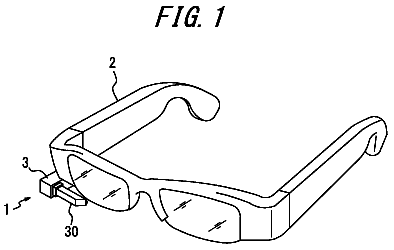
FIG. 42 is illustrative of an image projection apparatus 100 comprising a decentered optical system 1 according to one embodiment of the invention, which is built in eyeglasses G.
Detailed description of embodiments
A decentered optical system according to one embodiment as well as an image projection apparatus and an imaging apparatus, each incorporating that decentered optical system will now be explained with reference to the accompanying drawings.
An object of the invention is to provide an decentered optical system capable of projecting or taking images over a wide field of view at a high resolution albeit having a compact and simple structure as well as an image projection apparatus and an imaging apparatus, each incorporating that decentered optical system. Another object of the invention is to provide an image projection apparatus capable of viewing external images having reduced aberrations when the decentered optical system is used on a projection-onto-eyeball type image projection apparatus. Means for Achieving the Objects
FIG. 1 is a sectional view of the decentered optical system according to one embodiment of the invention.
A decentered optical system 1 according to one embodiment of the invention preferably comprises a first optical element 10 comprising at least three, mutually decentered optical surfaces including a first surface 11 through which light can transmit, a second surface 12 through which light can transmit and which is capable of internal reflection, and a third surface 13 through which light can transmit and which is capable of internal reflection, wherein said first optical element is filled inside with a medium having a refractive index greater than 1, and at least one of the three optical surfaces has a rotationally asymmetric configuration, and a second optical element 20 located on a second surface 12 side of said first optical element 10 and comprising at least two, mutually decentered optical surfaces including a first surface 21 through which light can transmit and a second surface 22 through which light can transmit and which has an outwardly concave configuration, wherein said second optical element is filled inside with a medium having a refractive index greater than 1, and at least one of said two optical surfaces has a rotationally asymmetric configuration, wherein said first optical element 10 and said second optical element 20 are spaced away from each other in an effective area through which a light beam passes, and satisfy the following condition (1): 0< D .sub.MAX /f≦ 0.3
where D.sub.MAX is the maximum value of a distance as measured in an effective area through which a light beam L passes on a section including a center chief ray Lc of the light beam L in a direction parallel with the center chief ray Lc between the second surface 12 of the first optical element 10 and the first surface 21 of the second optical element 20 , and f is the focal length of the decentered optical system 1 .
It is also preferable that the decentered optical system 1 according to the embodiment described herein comprises a first optical element 10 comprising at least three, mutually decentered optical surfaces including a first surface 11 through which light can transmit, a second surface 12 through which light can transmit and which is capable of reflection, and a third surface 13 through which light can transmit and which is capable of internal reflection, wherein said first optical element 10 is filled inside with a medium having a refractive index greater than 1, and at least one of the three optical surfaces has a rotationally asymmetric configuration; a second optical element 20 located on the second surface 12 side of the first optical element 10 and comprising at least two, mutually decentered optical surfaces including a first surface 21 through which light can transmit and a second surface 22 through which light can transmit and which has an outwardly concave configuration, wherein the second optical element 20 is filled inside with a medium having a refractive index greater than 1; and a third optical element 30 located on a third surface 13 side of the first optical element 10 and comprising at least two, mutually decentered optical surfaces including a first surface 31 through which light can transmit and which has an outwardly convex configuration and a second surface 32 through which light can transmit, wherein the third optical element 30 is filled inside with a medium having a refractive index greater than 1.
The merits obtainable from such construction of the decentered optical system 1 are now explained.
Referring first to the decentered optical system 1 described herein, there is the first optical element 10 used, which comprises at least three, mutually decentered optical surfaces: the first surface 11 through which light can transmit, the second surface 12 through which light can transmit and which is capable of reflection, and the third surface 13 through which light can transmit and which is capable of internal reflection, and is filled inside with a medium having a refractive index greater than 1. This permits the decentered prism to take an internal reflection optical path, and images observed or taken to be cleared of chromatic aberrations. It is also possible to prevent an increase in number of optical elements used for correction of chromatic aberrations, and fold an optical path by reflection to make the optical system itself smaller than a refractive optical system.
At least one of the three optical surfaces forming part of the first optical element 10 has preferably a rotationally asymmetric configuration because it can impart optical power to light beams and works more in favor of correction of decentration aberrations.
Further, by use of the second optical element 20 that is located on the second surface 12 side of the first optical element 10 , comprises at least two, mutually decentered optical surfaces: the first surface 21 through which light can transmit and the second surface 22 through which light can transmit, is filled inside with a medium having a refractive index greater than 1, and may be constructed from two mutually decentered, refracting surfaces, the opposite surfaces of the first 10 and the second optical element 20 may come close to each other and have a similar configuration. Referring to the second surface 22 of the second optical element 20 , the concave surface may be located externally in a position axially opposite to the viewer's eyeball (an entrance pupil in the case of an imaging optical system) so that the second surface 22 can be configured in such a way as to be concave with respect to the eye. In other words, two such surfaces may be modified in such a way as to hold back aberrations and conform well to a wide field of view.
How to keep track of light rays when the decentered optical system 1 is used with an image projection apparatus is now explained. A light ray exiting out from an image plane Im defined by the display surface of an image display device 50 enters the first optical element 10 from the first surface 11 , and is then reflected off from the second surface 12 . The light ray reflected off from the second surface 12 is reflected off from the third surface 13 , leaving the first optical element 10 from the second surface 12 . The light ray exiting out from the first optical element 10 enters the second optical element 20 from the first surface 21 , exiting out from the second surface 22 . The light ray exiting out from the second optical element 20 is projected onto a viewer's pupil E through an aperture stop S as an exit pupil.
The second optical element 20 allows for correction of aberrations including decentration aberrations because at least one of the two optical surfaces has a rotationally asymmetric curved configuration in such a way as to give optical power to light beams and make correction for decentration aberrations.
The first 10 and the second optical element 20 are spaced away from each other in the effective area through which light beams pass to provide for a total-reflection area by internal reflection off the second surface 12 of the first optical element 10 .
Further, satisfaction of Condition
by the decentered optical system 1 allows for location of the two optical elements with an appropriate separation in between. Exceeding the maximum value of Condition
causes the optical elements to be separated off. This in turn makes an eye relief or distance short, rendering images less observable, and causes the apparatus to gain in thickness and get large as well. Satisfaction of Condition
ensures that the opposing surfaces or the second 12 and the first surface 21 of the first 10 and the second optical element 20 come close in shape, resulting in reductions of various aberrations as well.
It is here to be noted that the focal length f may vary depending on the azimuth direction. In that case, the focal length f is preferably substituted by both a focal length f(X) in the X-direction and a focal length f(Y) in the Y-direction. It follows that the focal length f preferably satisfies both Conditions (1-1) and (1-2). 0< D .sub.MAX /f ( X )≦0.3 (1-1) 0< D .sub.MAX /f ( Y )≦0.3 (1-2)
The X- and Y-directions are here explained. In FIG. 1 , assume that the Z-direction is defined by a direction opposite to the direction of a center chief ray Lc exiting out from the decentered optical system 1 to the viewer's pupil E, the Y-Z plane is defined by a plane including a center chief ray before and after its bending or flexion by reflection, and the X-Z plane is defined by a direction passing through the emergent center chief ray Lc and vertical to the Y-Z plane. Thus, the Y-direction is defined by a direction vertical to the X-Z plane while the X-direction is defined by a direction vertical to the Y-Z plane.
As the lower limit value of Condition
is set at preferably 0.0002 and more preferably 0.00025, it facilitates prevention of contact of the first 10 with the second optical element 20 due to external pressure, and as the upper limit value of Condition
is set at preferably 0.2 and more preferably 0.1, it works more in favor of reductions of various aberrations because the second surface 12 of the first optical element 10 comes closer to the first surface 21 of the second optical element 20 . It is preferable for decentered optical system 1 to satisfy the following condition (1′): 0.00025< D .sub.MAX /f≦ 0.1 (1′)
According to the decentered optical system 1 described herein, it is possible to project or take images at high resolutions yet in a small-sized simple arrangement.
For the decentered optical system 1 described herein, it is preferable that the second surface 22 of the second optical element 20 is configured in such a way as to have a plurality of symmetric surfaces in the effective area. The second surface 22 of the second optical element 20 may be configured as a near-aplanatic surface inclusive of a spherical surface, a rotationally symmetric aspheric surface, a toric surface or a rotationally asymmetric surface to make the exit angle of emergent light small from its center to its periphery so that chromatic aberration of magnification occurring on that surface can be reduced or minimized.
In the decentered optical system 1 described herein, it is preferable for the first 10 and the second optical element 20 to satisfy the following Conditions
and (3). −2<( Dc−Dup )/ D .sub.MAX<2
−2<( Dc−Dun )/ D .sub.MAX<2
where Dc is a separation on said center chief ray between said first optical element and said second optical element,
Dup is a separation at a first end on the second surface side of said first optical element in said effective area, and
Dun is a separation at a second end opposite to said first end in said effective area.
Conditions
and
are provided to view or observe good images with the respective upper and lower light rays or, alternatively, to view or observe clear-cut images as far as the perimeter of the screen. Satisfaction of both conditions allows the second surface 12 of the first optical element 10 to become similar in shape to the first surface 21 of the second optical element 20 so that aberrations are reduced or held back.
Being short of the lower limits to Conditions
and
may possibly lead to interferences between the first 10 and the second optical element 20 . Exceeding the upper limit to Condition
may cause some considerable aberrations to occur on the second surface 12 of the first optical element 10 and the first surface 21 of the second optical element 20 due to the upper light rays, resulting in a lowering of the upper image quality as compared with the center. Exceeding the upper limit to Condition
causes some considerable aberrations to occur on the second surface 12 of the first optical element 10 and the first surface 21 of the second optical element 20 due to the lower light rays, resulting in a lowering of the lower image quality as compared with the center.
The lower limit value of each of Conditions
and
should be set at preferably −0.8, more preferably −0.5, and most preferably −0.2, and the upper limit value of each of Conditions
and
should be set at preferably 0.8, more preferably 0.5, and most preferably 0.2.
In the decentered optical system 1 described herein, the second surface 12 of the first optical element 10 and the first surface 21 of the second optical element 20 have substantially the same surface configuration in the effective area so that aberrations can be reduced or held back.
In the decentered optical system 1 described herein, the second surface 12 of the first optical element 10 and the first surface 21 of the second optical element 20 are each a rotationally asymmetric surface so that aberrations can be reduced or held back.
In the decentered optical system 1 described herein, the maximum value of the absolute value of the exit angles of all chief rays from the second surface 22 of the optical element 20 is not greater than 10° so that chromatic aberration of magnification can be reduced or held back. Exceeding the upper limit may possibly give rise to as much chromatic aberration as cannot be corrected by other optical element.
If the maximum value of the absolute value of the exit angles of all chief rays from the second surface 22 of the second optical element 20 is not greater than 50, the decentered optical element 1 described herein works more in favor of chromatic aberration-of-magnification reductions.
In the decentered optical system 1 described herein, it is preferable for the second surface 22 of the second optical element 20 to satisfy the following Condition (4). −4≦ R 1 P .sub.o /ER≦− 0.01
where R1P.sub.o is the radius of curvature of the second surface 22 of the second optical element 20 , and
ER is the eye relief.
Satisfaction of Condition
ensures that the second surface 22 of the second optical element 20 is configured as a near-aplanatic surface so that the exit angle of emergent light from the second surface 22 can be kept very small (preferably down to about 0°) from the center to the perimeter of the screen thereby keeping chromatic aberration of magnification from occurring on that surface. Note here that the radius of curvature R1P.sub.o of the second surface 22 of the second optical element 20 is preferably of the order of −8 mm≦R1P.sub.o≦−100 mm and the eye relief ER is preferably of the order of 8 mm≦ER≦45 mm.
It is also understood that the radius of curvature R1P.sub.o of the second surface 22 of the second optical element 20 may vary depending on the azimuth direction. In that case, the radius of curvature R1P.sub.o of the second surface 22 of the second optical element 20 may be substituted by both the radius of curvature R1P.sub.o(X) in the X-direction and the radius of curvature R1P.sub.o(Y) in the Y-direction: it may satisfy the following two Conditions (4-1) and (4-2). −4≦ R 1 P .sub.o( X )/ ER≦− 0.01 (4-1) −4≦ R 1 P .sub.o( Y )/ ER≦− 0.01 (4-2)
The lower limit value of Condition
should be set at preferably −3.0 and more preferably −2.0, and the upper limit value of Condition
should be set at preferably −0.3 and more preferably −0.5.
In the decentered optical system 1 described herein, it is preferable for the second surface 22 of the second optical element 20 to satisfy the following Condition (5). −4≦ R 1 P .sub.o /f≦− 0.1
where R1P.sub.o is the radius of curvature of the second surface 22 of the second optical element 20 , and
f is the focal length of the overall decentered optical system 1 .
In a retrofocus arrangement in negative-positive order, the focal length f is shorter than the eye relief as viewed in inverse or back ray tracing, working in favor of taking hold of the eye relief ER. However, the focal length f is not that largely different from the eye relief ER. Therefore, there is the same advantage obtained as in Condition (4): it is possible to hold back the occurrence of chromatic aberration of magnification. Note here that the radius of curvature R1P.sub.o of the second surface 22 of the second optical element 20 is preferably of the order of −8 mm≦R1P.sub.o≦−100 mm and the eye relief ER is preferably of the order of 8 mm≦ER≦45 mm.
It is also understood that the radius of curvature R1P.sub.o of the second surface 22 of the second optical element 20 may vary depending on the azimuth direction. In that case, the radius of curvature R1P.sub.o of the second surface 22 of the second optical element 20 may be substituted by both the radius of curvature R1P.sub.o(X) in the X-direction and the radius of curvature R1P.sub.o(Y) in the Y-direction: it may satisfy the following two Conditions (5-1) and (5-2). −6≦ R 1 P .sub.o( X )/ f≦− 0.1 (5-1) −6≦ R 1 P .sub.o( Y )/ f≦− 0.1 (5-2)
The lower limit value of Condition
should be set at preferably −4.0 and more preferably −3.5, and the upper limit value of Condition
should be set at preferably −0.4 and more preferably −0.7.
In the decentered optical system 1 described herein, it is preferable for the second surface 22 of the second optical element 20 to satisfy the following Condition (5′). −4.2≦ R 1 P .sub.o /f≦− 0.4 (5′) where R1P.sub.o is the radius of curvature of the second surface 22 of the second optical element 20 , and
f is the focal length of the overall decentered optical system 1 .
By satisfaction of this Condition (5′), the exit angle of emergent light from the second surface 22 can be smaller so much so that the amount of chromatic aberration of magnification occurring at this surface can be further reduced.
Preferably, the decentered optical system 1 described herein further comprises a third optical element 30 having at least two, mutually decentered optical surfaces including a first 31 and a second surface 32 which are located on the third surface 13 side of the first optical element 10 through which light can transmit, and filled inside with a medium having a refractive index greater than 1.
When an external world is observed only through the first 10 and the second optical element 20 , there is only an unnatural image obtained. As the third optical element 30 having mutually decentered surfaces is located on the external world side of the first optical element 10 , it allows combined power to get small with respect to external light (preferably down to nearly zero). This in turn makes it possible for the viewer to make natural, substantially distortion-free see-through observations at a magnification close to almost 1.
Further, by use of the third optical element 30 comprising at least two optical surfaces including the first surface 31 which is located on the third surface 13 side of the first optical element 10 , through which light can transmit and which has an outwardly convex shape, and the second surface 32 through which light can transmit, and filled inside with a medium having a refractive index greater than 1, combined power relative to external light is reduced (to preferably almost zero), and it is possible for the viewer to make natural, substantially distortion-free see-through observations at a magnification close to almost 1.
Referring here to a direct-vision optical path through the decentered optical system 1 , a light ray exiting out from an image plane (not shown) enters the third optical element 30 from the first surface 31 , exiting out from the second surface 32 . The light ray exiting out from the third optical element 30 enters the first optical element 10 from the third surface 13 , exiting out from the second surface 12 . The light ray exiting out from the first optical element 10 enters the second optical element 20 from the first surface 21 , exiting out from the second surface 22 . Exiting out from the second optical element 20 , the light ray passes through the aperture stop S as an exit pupil for projection onto the viewer's eye E.
In the decentered optical system 1 described herein, it is preferable for the second 20 and the third optical element 30 to satisfy the following Condition (6). 0.1| R 2 Pi−R 1 P .sub.o |/D 2 Pi 1 P .sub.o≦12
where R2 Pi is the radius of curvature of the first surface 31 of the third optical element 30 ,
R1P.sub.o is the radius of curvature of the second surface 22 of the second optical element 20 , and
D2PilP.sub.o is a distance between the first surface 31 of the third optical element 30 and the second surface 22 of the second optical element 20 in a direction along the center chief ray of a light beam.
The position of the first surface of the third optical element 30 is separated off the second surface 22 of the second optical element 20 by a distance corresponding to the total thickness of the first, second and third optical elements 10 , 20 and 30 . For this reason, the angle of incidence of external light on the optical surface with the position of the viewer's pupil as the entrance pupil must be reduced as much as possible. This is the condition to hold back various aberrations thereby making observations of natural external images. In an extreme case where the angle of incidence of external light is zero, the surface of incidence becomes an aplanatic surface where spherical aberration, coma and astigmatism will not occur.
Indeed, however, the decentered optical system 1 is generally a non-rotationally symmetric free-form surface optical system; the first surface of the supplementary prism 1 does not provide any perfect aplanatic surface for the reasons of a power layout that has preferably a less negative power, and the like. A preferential condition here is to bring the power of the direct-vision optical path relative to external light close to zero rather than the aplanatic condition for the second surface 2 of the supplementary prism 2 . It is thus preferable to satisfy Condition (6).
It is here to be noted that the radius of curvature may vary depending on the azimuth direction. In that case, the radius of curvature R2Pi may be substituted by both the radius of curvature R2Pi(X) in the X-direction and the radius of curvature R2Pi(Y) in the Y-direction, and the radius of curvature R1P.sub.o may be substituted by both the radius of curvature R1P.sub.o(X) in the X-direction and the radius of curvature R1P.sub.o(Y) in the Y-direction: it is preferable to satisfy both the following Conditions (6-1 and (6-2). 0.1≦| R 2 Pi ( X )− R 1 P .sub.o( X )|/ D 2 Pi 1 P .sub.o≦12 (6-1) 0.1≦| R 2 Pi ( Y )− R 1 P .sub.o( Y )|/ D 2 Pi 1 P .sub.o≦12 (6-2)
The X- and Y-directions are here explained. In FIG. 1 , assume that the Z-direction is defined by a direction opposite to the direction of a center chief ray Lc exiting out from the decentered optical system 1 to the viewer's pupil E, the Y-Z plane is defined by a plane including a center chief ray before and after its bending or flexion by reflection, and the X-Z plane is defined by a direction passing through the emergent center chief ray Lc and vertical to the Y-Z plane. Thus, the Y-direction is defined by a direction vertical to the X-Z plane while the X-direction is defined by a direction vertical to the Y-Z plane.
The lower limit value of Condition
should be set at preferably 0.2 and more preferably 0.5, and the upper limit value of Condition
should be set at preferably 10 and more preferably 9. With respect to the above-defined Y-direction, the lower limit value of Condition (6-2) should be set at preferably 0.3 and more preferably 0.5, and the upper limit value of Condition (6-2) should be set at preferably 10, more preferably 9 and most preferably 2.
In the decentered optical system 1 described herein, the second surface 12 of the first optical element 10 and the first surface 21 of the second optical element 20 have the same surface configuration in the effective area so that aberrations can be held back.
In the decentered optical system 1 described herein, it is preferable that the second 12 and the third surface 13 of the first optical element 10 are located in opposition to each other, and the third surface 13 of the first optical element 10 is a reflecting surface concave on the second surface 12 side of the first optical element 10 .
The second surface 12 of the first optical element 10 that is an internal reflecting surface also serves as an exit surface from which light exits out after internal reflection takes place twice: it has two optical actions. This does not only contribute more to the bending effect of this prism, but is also effective for reducing the size of the optical element itself. The third surface 13 of the first optical element 10 that is a reflecting surface having power is a so-called back-surface concave mirror having a concave surface shape, and it is this surface that bears a primary positive power of the overall optical system. Although this surface must have the necessary positive power, resulting in the occurrence of spherical aberration, coma and so on, yet they are corrected by the negative power of the second surface that is a reflecting surface.
In the decentered optical system 1 described herein, it is preferable to cement together the third surface 13 of the first optical element 10 and the second surface 32 of the third optical element 30 . Cementing allows for integration of the optical elements, dispensing with any adjustment and leading to a lesser number of assembling steps. Cementing is also effective for a coated mirror such as a half mirror, because the coated surface is unlikely to be exposed to the outside air, resulting in improvements in resistance.
In the decentered optical system 1 described herein, the third surface 13 of the first optical element 10 is preferably a rotationally asymmetric surface. The third surface 13 of the first optical element 10 bears a primary positive power of the decentered optical system 1 . As this surface is defined by the rotationally asymmetric surface, it allows for correction for decentration and other aberrations occurring thereat, leading to improvements in the optical performance of the overall optical system.
In the decentered optical system 1 described herein, the second surface 12 of the first optical element 10 is preferably a rotationally asymmetric surface. The second surface 12 of the first optical element 10 has two optical actions: internal reflection and transmission for exiting out or, the second surface 12 has an effect on two aberration corrections. As is the case with the third surface, this surface is defined by the rotationally asymmetric surface that has a striking effect on correction of decentration and other aberrations and, hence, contributes to improvements in the optical performance of the overall optical system.
In the decentered optical system 1 described herein, the first surface 11 of the first optical element 10 is preferably a rotationally asymmetric surface. The first surface 11 of the first optical element 10 is proximate to the plane of the image display device, through which a light beam having a small diameter transmits, and acts to make correction for off-axis aberrations.
In the decentered optical system 1 described herein, the second 20 and the third optical element 30 preferably satisfy the following Condition (7). 0.1≦φ2/φ1≦1.3
where φ1 is the power of the second surface of said second optical element at a point of intersection with the center chief ray, and
φ2 is the power of the first surface of said third optical element at a point of intersection with the center chief ray.
Condition
is necessary to observe as natural external images as possible. Being less than the lower limit to Condition
causes the see-through magnification of external images to get low with the result that there is a large difference with the external images seen through the naked eyes. Exceeding the upper limit to Condition
causes the curvature of the second surface of the second optical element to get small, resulting in incapability of making correction for chromatic aberration of magnification upon viewing of electronic images and a lowering of the optical performance of the overall optical system.
It is here to be appreciated that the power of the surface may vary depending on the azimuth direction. In that case, the power φ1 of the surface may be substituted by both the power φ1(X) of the surface in the X-direction and the power φ1(Y) of the surface in the Y-direction, and the power φ2 of the surface may be substituted by both the power φ2(X) of the surface in the X-direction and the power φ2(Y) of the surface in the Y-direction. In other words, it is preferable to satisfy the following Conditions (7-1) and (7-2). 0.15≦φ2( X )/φ1( X )≦1.3 (7-1) 0.15≦φ2( Y )/φ1( Y )≦1.3 (7-2)
The lower limit value of Condition
should be set at preferably 0.25 and more preferably 0.3, and the upper limit value of Condition
should be set at preferably 1.1 and more preferably 0.95.
In the decentered optical system 1 described herein, the third surface 13 of the first optical element 10 has preferably such a half mirror structure as to reflect off light from within the first optical element 10 and allow for transmission of light from outside the first optical element 10 .
The third surface 13 of the first optical element 10 that is opposite to the third optical element 30 and acts as an internal reflecting surface may be configured as a half mirror to observe external images and provide simultaneous viewing of electronic images on the image display device or the like in a superposed way.
The description continues in the full USPTO document.
 Lapsed, fee not paid16 drawings