 Lapsed, fee not paid32 drawings
Cameras, Displays & Optics · US 9,804,364 B2
Image pickup lens
An imaging lens for a solid-state imaging sensor includes, in order from an object side to an image side of the imaging lens, a first through sixth lens.
US 9,804,370 B2 · Assignee: Canon Kabushiki Kaisha · Inventors: Sakamoto; Masaru
Sheet 1 of 16 from the published document. All sheets in the USPTO PDF
A zoom lens system including, in order from an object side to an image side, a first lens unit having a positive refractive power that does not move for zooming, a second lens unit having a negative refractive power that moves during zooming, and a third lens unit having a positive refractive power that moves during zooming. In the zoom lens system, a distance between lens units that are adjacent to each other changes during zooming, the first lens unit includes a first a-lens unit that does not move for focusing, and a first b-lens unit that moves from the image side towards the object side during focusing from an infinite object to a near object, and the first a-lens unit comprises two positive lenses and two negative lenses.
Field of the Invention The present disclosure relates to a zoom lens system and an image capturing apparatus including the same, and is suitable for, for example, a television camera for broadcasting, a video camera, a digital still camera, a monitoring camera, a film camera. Description of Related Art In recent years, in image capturing apparatuses, such as television cameras, silver halide film cameras, digital cameras, and video cameras, there is a demand for a zoom lens system that has a wide view angle and a high zoom ratio, and, moreover, with a high optical performance. For example, Japanese Patent Laid-Open No. 2001-183584 discloses a four-unit zoom lens system that is suitable for television cameras and that includes, from the object side to the image side, a positive first lens unit, a second lens unit having a negative refractive power that moves during zooming, a third lens u
1 of 16 drawing sheets so far from the published document, cropped to the drawing. Every sheet is in the USPTO PDF.
What the patent claimed, word for word. All of it is now free to use.
Field of the Invention
The present disclosure relates to a zoom lens system and an image capturing apparatus including the same, and is suitable for, for example, a television camera for broadcasting, a video camera, a digital still camera, a monitoring camera, a film camera.
Description of Related Art
In recent years, in image capturing apparatuses, such as television cameras, silver halide film cameras, digital cameras, and video cameras, there is a demand for a zoom lens system that has a wide view angle and a high zoom ratio, and, moreover, with a high optical performance.
For example, Japanese Patent Laid-Open No. 2001-183584 discloses a four-unit zoom lens system that is suitable for television cameras and that includes, from the object side to the image side, a positive first lens unit, a second lens unit having a negative refractive power that moves during zooming, a third lens unit having a positive refractive power, and a fourth lens unit that does not move for zooming. Furthermore, a segmental lens unit on the most image side of the first optical unit performs focusing while a segmental lens unit on the object side of the first optical unit is fixed during focusing.
The above Japanese Patent Laid-Open No. 2001-183584 discloses a zoom lens system that has a zoom ratio of about 65 times and an angle of view for shooting of about 60° at a wide angle end, and that achieves wide angle, high magnification, and high performance through, for example, selection of glass materials and configuration of the lenses in an appropriate manner.
In the zoom lens system disclosed in Japanese Patent Laid-Open No. 2001-183584, variation in axial chromatic aberration during zooming, variation in axial chromatic aberration due to change in object distance, and change in the performance around the telescopic end tend to increase with increase in magnification. Therefore, further improvements in the zoom lens system remain necessary.
The present disclosure is directed to a zoom lens system including, in order from an object side to an image side, a first lens unit having a positive refractive power that does not move for zooming, a second lens unit having a negative refractive power that moves during zooming, and a third lens unit having a positive refractive power that moves during zooming. In the zoom lens system, a distance between lens units that are adjacent to each other changes during zooming, the first lens unit includes a first a-lens unit that does not move for focusing, and a first b-lens unit that moves from the image side towards the object side during focusing from an infinite distant object to a nearby object, and the first a-lens unit comprises two positive lenses and two negative lenses.
Further features of the present invention will become apparent from the following description of exemplary embodiments with reference to the attached drawings.
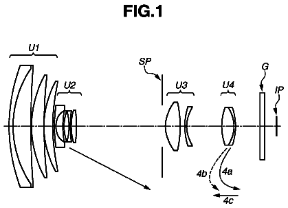
FIG. 1 is a cross-sectional view of a zoom lens system focused to infinity at a wide angle end, according to a first embodiment.
FIGS. 2A and 2B are aberration diagrams of the zoom lens system at a wide angle end and at a telescopic end focused at an object distance of 15 m, according to the first embodiment.
FIG. 3 is a cross-sectional view of a zoom lens system focused to infinity at a wide angle end, according to a second embodiment.
FIGS. 4A and 4B are aberration diagrams of the zoom lens system at a wide angle end and at a telescopic end focused at an object distance of 15 m, according to the second embodiment.
FIG. 5 is a cross-sectional view of a zoom lens system focused to infinity at a wide angle end, according to a third embodiment.
FIGS. 6A and 6B are aberration diagrams of the zoom lens system at a wide angle end and at a telescopic end focused at an object distance of 15 m, according to the third embodiment.
FIG. 7 is a cross-sectional view of a zoom lens system focused to infinity at a wide angle end, according to a fourth embodiment.
FIGS. 8A and 8B are aberration diagrams of the zoom lens system at a wide angle end and at a telescopic end focused at an object distance of 15 m, according to the fourth embodiment.
FIG. 9 is a cross-sectional view of a zoom lens system focused to infinity at a wide angle end, according to a fifth embodiment.
FIGS. 10A and 10B are aberration diagrams of the zoom lens system at a wide angle end and at a telescopic end focused at an object distance of 15 m, according to the fifth embodiment.
FIG. 11 is a schematic diagram of an image capturing apparatus including a zoom lens system of the present disclosure.
In a positive lead type zoom lens system, in order to obtain a high optical performance throughout the entire zoom and focus range while maintaining a wide view angle and a high magnification, it is important to set the configuration of the first lens unit, the refractive power, and the focus method in an appropriate manner. Without the above configuration being appropriately set, it is difficult to obtain a zoom lens system having a high optical performance with a wide view angle and a high zoom ratio throughout the entire zoom and focus range.
The present disclosure provides a zoom lens system with a wide view angle and a high zoom ratio throughout the entire zoom and focus range while achieving a favorable zooming operation, and an image capturing apparatus including the zoom lens system.
Hereinafter, exemplary embodiments of the present disclosure will be described in detail with reference to the accompanying drawings.
A zoom lens system of the present disclosure includes, in order from the object side to the image side, a first lens unit having a positive refractive power that does not move for zooming, a second lens unit having a negative refractive power that moves during zooming, and a third lens unit having a positive refractive power that moves during zooming.
Herein, the lens unit not moving to zoom means that the lens unit is not moved for the purpose of zooming alone, but when zooming and focusing are performed at the same time, a given lens unit may be moved for focusing.
FIG. 1 is a cross-sectional view of lenses of a first exemplary embodiment (a first numerical embodiment) of the present disclosure focused to infinity at a wide angle end. FIGS. 2A and 2B are aberration diagrams when the lenses at a wide angle end and at a telescopic end, respectively, are focused to a distance of 15 m. Note that the values of the object distances are distances in which the numerical embodiments described later are expressed in millimeters (mm). The object distance is a distance from the first lens surface to the plane (physical location) where the object is located during an imaging operation. The same applies hereinafter to all embodiments.
FIG. 3 is a cross-sectional view of lenses of a second exemplary embodiment (a second numerical embodiment) of the present disclosure focused to infinity at a wide angle end. FIGS. 4A and 4B are aberration diagrams when the lenses at a wide angle end and at a telescopic end, respectively, are focused to a distance of 15 m.
FIG. 5 is a cross-sectional view of lenses of a third exemplary embodiment (a third numerical embodiment) of the present disclosure focused to infinity at a wide angle end. FIGS. 6A and 6B are aberration diagrams when the lenses at a wide angle end and at a telescopic end, respectively, are focused to a distance of 15 m.
FIG. 7 is a cross-sectional view of lenses of a fourth exemplary embodiment (a fourth numerical embodiment) of the present disclosure focused to infinity at a wide angle end. FIGS. 8A and 8B are aberration diagrams when the lenses at a wide angle end and at a telescopic end, respectively, are focused to a distance of 15 m.
FIG. 9 is a cross-sectional view of lenses of a fifth exemplary embodiment (a fifth numerical embodiment) of the present disclosure focused to infinity at a wide angle end. FIGS. 10A and 10B are aberration diagrams when the lenses at a wide angle end and at a telescopic end, respectively, are focused to a distance of 15 m.
In each of the cross-sectional views of the lenses, the left side is the subject (the object) side (the front side) and the right side is the image side (the rear side). In the cross-sectional view of the lenses, reference numeral U 1 is the first lens unit having a positive refractive power that does not move for zooming. Reference numeral U 1 b is a focus lens unit in the first lens unit U 1 and moves to the object side when performing focus adjustment from an infinite object to a near object. Reference numeral U 1 a is a stationary lens unit in the first lens unit U 1 and does not move for focusing. Reference numeral U 1 a denotes a first a-lens unit and reference numeral U 1 b denotes a b-lens unit in the first lens unit U 1 .
Reference numeral U 2 is the second lens unit having a negative refractive power that moves during zooming. Reference numeral U 3 is the third lens unit having a positive refractive power that moves during zooming.
In the first, second, fourth, and fifth exemplary embodiments, reference numeral U 4 is the fourth lens unit having a positive refractive power that moves during zooming. Reference numeral U 5 is a fifth lens unit (a relay lens unit) for image forming that does not move for zooming. Reference label BK a glass block equivalent to an optical filter or the like.
In the third exemplary embodiment ( FIG. 5 ), reference numeral U 4 is a fourth lens unit (a relay lens unit) for image forming that does not move for zooming.
The zoom lens system of each exemplary embodiment performs zooming and correction of the image plane variation associated with zooming by changing each of the lens distances while moving on the optical axis.
Reference numeral IP is an image plane or image surface and corresponds to an image pickup surface of a solid-state image pick up element (photoelectric conversion element), such as a CCD sensor or a CMOS sensor. In each spherical aberration diagram, the solid line represents an e-line and the two-dot chain line represents a g-line. In each astigmatism graph, the dotted line represents a meridional image surface of an e-line, and the solid line represents a sagittal image surface of the e-line. In each chromatic aberration graph, the two-dot chain line represents chromatic aberration of magnification at a g-line. Fno represents an F-number, and ω represents a half angle of view (degree).
In each aberration diagram, the spherical aberration is drawn in a scale of 0.2 mm, the astigmatism in 0.2 mm, the curvature in 5%, and the magnification chromatic aberration in 0.05 mm.
The zoom lens system of the present disclosure specifies conditions for obtaining a high optical performance with a high zoom ratio and a wide view angle throughout the entire zoom and focus range by specifying the focusing system of the first lens and the lens configuration of the first lens unit.
Included in the zoom lens system is, in order from the object side to the image side, the first lens unit having a positive refractive power that does not move for zooming, the second lens unit having a negative refractive power that moves during zooming, and the third lens unit having a positive refractive power that moves during zooming. Furthermore, the distance between adjacent lens units change during zooming, and the first lens unit includes the first a-lens unit that does not move for focusing and the first b-lens unit that moves to the object side from the image side during focusing from an infinite object to a near object. Furthermore, the first a-lens unit is formed of two positive lenses and two negative lenses.
With the configuration described above, a zoom lens system having a high optical performance with a high zoom ratio and a wide view angle, and moreover, a zoom lens system having the above high optical performance throughout the entire zoom and focus range is obtained.
In each exemplary embodiment, the first lens unit includes two lens units, namely, the first a-lens unit on the object side and a first b-lens unit on the image side. The first a-lens unit on the object side does not move for focusing and the first b-lens unit on the image side moves during focusing. When focusing from an infinite object to a near object, focus adjustment is made by moving from the image side to the object side.
In the above case, upon performance of focusing, the height of the axial ray and that of the off axial ray changes and, accordingly, aberration variation occurs. Generally, the aberration variation increases towards the telephoto side. In order to suppress the above, the amount of aberration occurring in the first a-lens unit on the object side that has a large ray height needs to be suppressed. The aberration variation can be classified into chromatic aberration and aberration attributed to a standard wavelength.
The first a-lens unit having two negative lenses and two positive lenses increases the number of lens surfaces in the first a-lens unit and can suppress the amount of aberration occurring on the surfaces in the first a-lens unit. Furthermore, plural combinations of adjoining surfaces (a convexity and a concavity, in the first exemplary embodiment, the second surface and the third surface, and the sixth surface and the seventh surface) that have close curvatures and in which the aberrations are cancelled out with respect to each other can be provided. Since the combinations can correct high order aberrations, by providing plural combinations, the aberrations occurring in the first a-lens unit from a low order aberration to a high order aberration can be corrected in a favorable manner.
Furthermore, while maintaining aberration sensitivity and the optical performance, dispersion (Abbe number νd) of the positive lens and the negative lens can be brought close to each other. Accordingly, related to the selection of the glass materials, the dispersion characteristics (partial dispersion ratios θgf) of the positive lens and the negative lens can be brought close to each other and the chromatic aberration of the first a-lens unit can be corrected in a favorable manner throughout the entire wavelength.
Another feature of the zoom lens system of the present disclosure is that a condition for obtaining a zoom lens system having a high zoom ratio and a wide view angle, moreover, a zoom lens system having a high optical performance throughout the entire zoom and focus range is specified by specifying the configuration of the lenses and the refractive powers of the lens units of the fourth lens unit and after. By configuring the fourth lens unit and after so that the fourth lens unit has a positive refractive power that moves during zooming and that the fifth lens unit is provided for image forming, or so that the fourth lens unit is provided for image forming, high zoom ratio can be achieved while maintaining the total lens length.
Another feature of the zoom lens system of the present disclosure is that the ratio of the focal length of the negative lens of the first a-lens unit and the ratio of dispersion of the lens material thereof are specified. With the above, chromatic aberration and various aberrations of the first a-lens unit can be suppressed from occurring and aberration occurring due to focusing can be favorably corrected.
When the focal length of the negative lens disposed on the object side among the two negative lenses is fn1 and the Abbe number thereof is νn1, and when the focal length of the negative lens disposed on the image side is fn2 and the Abbe number thereof is νn2, the following conditional expressions hold true. 0.30< fn 1/ fn 2<2.50
0.30<ν n 1/ν n 2<2.70
Note that the Abbe number is expressed by the following equation when the refractive indexes at the F-line (486.1 nm), the d-line (587.6 nm), and the C-line (656.3 nm) of the Fraunhofer lines are Nd, NF, and NC, respectively. ν d =( Nd− 1)/( NF−NC )
When under the lower limit of the conditional expression (1), the refractive power of the negative lens disposed on the object side that has a large off axial ray height becomes strong, and the distortion on the wide-angle side and the curvature of the image surface worsen. Furthermore, the sensitivities in the spherical aberration and the like of the first a-lens unit increase. When exceeding the upper limit of the conditional expression (1), the refractive power of the negative lens disposed on the object side becomes weak, and the retrofocusing of the first lens unit will become difficult and reduction in size will become difficult. Furthermore, the refractive power of the negative lens disposed on the image side becomes strong and the spherical aberration and the like of the first a-lens unit increase.
When under the lower limit of the conditional expression (2), the dispersion of the negative lens disposed on the object side that has a large off axial ray height becomes strong and the negative lens disposed on the image side that has a small off axial ray height becomes weak, making it difficult to achieve both corrections of the axial chromatic aberration and the magnification chromatic aberration. When exceeding the upper limit of the conditional expression (2), the dispersion of the negative lens disposed on the object side that has a large off axial ray height becomes weak and the negative lens disposed on the image side that has a small off axial ray height becomes strong, making it difficult to achieve corrections of both the axial chromatic aberration and the magnification chromatic aberration.
More preferably, it is desirable to set the conditional expressions
and
in the following manner. 0.40< fn 1/ fn 2<1.90 (1a) 0.35<ν n 1/ν n 2<2.50 (2a)
As another feature of the zoom lens system of the present disclosure, the condition for suppressing various aberrations of the first a-lens unit from occurring and for favorably correcting the aberration occurring due to focusing is specified by specifying the ratio between the focal length of the negative lens of the first a-lens unit and the focal length of the first lens unit.
When the focal length of the first lens unit is f1, the following conditional expressions hold true. 1.30<| fn 1/ f 1|<5.00
1.50<| fn 2/ f 1|<6.00
When under the lower limit of the conditional expression (3), the refractive power of the negative lens disposed on the object side that has a high off axial ray becomes strong, and the distortion on the wide-angle side and the curvature of the image surface worsen. Furthermore, the sensitivities in the spherical aberration and the like of the first a-lens unit increase. When exceeding the upper limit of the conditional expression (3), the refractive power of the negative lens disposed on the object side becomes weak, and it will be difficult to perform retrofocusing of the first lens unit and to achieve reduction in size.
When under the lower limit of the conditional expression (4), the refractive power of the negative lens disposed on the image side becomes strong and the spherical aberration and the like of the first a-lens unit increase. When exceeding the upper limit of the conditional expression (4), the refractive power of the negative lens disposed on the object side becomes weak, making it difficult to favorably correct the chromatic aberration and various aberrations of the first a-lens unit; accordingly, the occurrence of aberration due to focusing increases.
More preferably, it is desirable to set the conditional expressions
and
in the following manner. 1.60<| fn 1/ f 1|<4.50 (3a) 1.70<| fn 2/ f 1|<4.70 (4a)
As another feature, the zoom lens system of the present disclosure specifies the condition of the dispersion characteristic of the lens material of the first a-lens unit to specify the condition for favorably correcting the variation in the axial chromatic aberration due to focusing, the axial chromatic aberration due to zooming, and the variation in the magnification chromatic aberration.
When the average value of the Abbe number and the average value of the partial dispersion ratio of the positive lenses among the lenses that configure the first a-lens unit are νpa and θpa, respectively, and when the Abbe number and the partial dispersion ratio of the negative lens with the largest Abbe number among the negative lenses that configure the first a-lens unit are νnx and θnx, respectively, the following conditional expression holds true. −0.50500×10.sup.−3<(θ pa−θnx )/(ν pa−νnx )<0.20000×10.sup.−3
Note that the partial dispersion ratio is expressed by the following expression when the refractive index of the g-line (435.8 nm) of the Fraunhofer line is Ng. θ=( Ng−NF )/( NF−NC )
When under the lower limit of the conditional expression (5), the chromatic aberration correction effect of the first a-lens unit becomes insufficient making it difficult to favorably correct the variation in the axial chromatic aberration due to focusing, the axial chromatic aberration due to zooming, and the variation in the magnification chromatic aberration. When exceeding the upper limit of the conditional expression (5), since the selection of the glass material becomes limited, the dispersions of the positive lens and the negative lens of the first a-lens unit become close to each other and the refractive power of each of the lenses of the first a-lens unit increases. As a result, it is difficult to perform a favorable correction of coma aberration variation due to focusing.
More preferably, it is desirable to set the conditional expression
in the following manner. −0.50000×10.sup.−3<(θ pa−θnx )/(ν pa−νnx )<0.100000×10.sup.−3 (5a)
As another feature of the zoom lens system of the present disclosure, the condition for achieving a favorable correction of the aberration throughout the entire zooming range while having high magnification is specified by specifying the focal lengths of the first lens unit and the second lens unit. When the focal length of the second lens unit is f2, the following conditional expression holds true. 6.00<| f 1/ f 21<13.00
When exceeding the upper limit of the conditional expression (6), since the focal length of the first lens unit becomes relatively long, the lens diameter of the first lens unit becomes large making it difficult to widen the angle. When under the lower limit of the conditional expression (6), since the focal length of the first lens unit becomes relatively short, it is difficult to correct the spherical aberration variation and the axial chromatic aberration on the telephoto side.
More preferably, it is desirable to set the conditional expression
in the following manner. 7.50<| f 1/ f 2|<11.00 (6a)
An another feature of the zoom lens system of the present disclosure is that the ratio between the combined focal length of the negative lenses of the first a-lens unit, the combined focal length of the positive lenses of the first a-lens unit, and the focal length of the first lens unit are specified. With the above, various aberrations of the first a-lens unit are suppressed from occurring and aberration occurring due to focusing can be favorably corrected.
When the combined focal length of the positive lenses among the lenses configuring the first a-lens unit is fpa, the combined focal length of the negative lenses thereof is fna, the following conditional expressions hold true. 0.75<| fna/fpa|< 1.30
1.00<| fna/f 1|<2.00
1.00<| fpa/f 1|<2.20
Note that combined focal length fx of the plurality of lenses is expressed in the following manner when each of the focal length of the plurality of lenses is
f1, f2, f3, . . . .
1/fx=1/f1+1/f2+1/f3+ . . . .
When under the lower limit of the conditional expression (7), the refractive power of each of the lenses of the first a-lens unit becomes strong and it is difficult to correct the spherical aberration and the coma aberration at the telescopic end. Furthermore, the sensitivities in the spherical aberration and the like of the first a-lens unit increase. When exceeding the upper limit of the conditional expression (7), achromatization of the first a-lens unit becomes insufficient; accordingly, variation in chromatic aberration due to focusing increases.
When under the lower limit of the conditional expression (8), the refractive power of the negative lens becomes strong, and the distortion on the wide-angle side and the curvature of the image surface worsen. Furthermore, the sensitivities in the spherical aberration and the like of the first a-lens unit increase. When exceeding the upper limit of the conditional expression (8), achromatization of the first a-lens unit becomes insufficient; accordingly, variation in chromatic aberration due to focusing increases.
When under the lower limit of the conditional expression (9), the refractive power of the positive lens becomes strong and it is difficult to correct the spherical aberration and the coma aberration at the telescopic end. Furthermore, the sensitivities in the spherical aberration and the like of the first a-lens unit increase. When exceeding the upper limit of the conditional expression (9), achromatization of the first a-lens unit becomes insufficient; accordingly, variation in chromatic aberration due to focusing increases.
More preferably, it is desirable to set the conditional expressions (7), (8), and
in the following manner. 0.85<| fna/fpa|< 1.10 (7a) 1.10<| fna/f 1|<1.70 (8a) 1.10<| fpa/f 1|<1.90 (9a)
Description of each of the exemplary embodiments will be given next. First Exemplary Embodiment
In the cross-sectional view of lenses of a first exemplary embodiment in FIG. 1 , reference numeral U 1 is a first lens unit having a positive refractive power that does not move for zooming. The first lens unit U 1 includes, in the order from the object side to the image side, a first a-lens unit U 1 a that does not move for focusing, and a first b-lens unit U 1 b that moves during focusing. When focusing a near object from an infinite object, the first b-lens unit U 1 b for focusing moves towards the object side as the object distance changes from long distance to short distance.
Reference numeral U 2 and U 3 are a second lens unit having a negative refractive power and a third lens unit (a variator lens unit) having a positive refractive power, respectively, that move during zooming. The second lens unit U 2 and the third lens unit U 3 perform magnification from a wide angle end to a telescopic end by moving on the optical axis. Reference numeral U 4 is a fourth lens unit (a compensator lens unit) having a positive refractive power that moves during zooming. The fourth lens unit U 4 moves on the optical axis while interlocking with the movement of the second and third lens units U 2 and U 3 and corrects the image plane variation associated with the magnification. Reference numeral SP is an aperture diaphragm. Reference numeral U 5 is a fifth lens unit (a relay lens unit R) having a positive refractive power that does not move during zooming. The aperture diaphragm SP is disposed between the fourth lens unit U 4 and the fifth lens unit U 5 .
The present exemplary embodiment satisfies each of the conditional expressions
to (9); accordingly, a zoom lens system with a high zoom ratio and a high performance, and, moreover, with little degradation in performance caused by manufacturing error can be obtained. Second Exemplary Embodiment
A zoom lens system of a second exemplary embodiment in FIG. 3 has a zoom type, such as the number of lens unit, the refractive power of each lens unit, and the condition in which each lens unit move while focusing, that is similar to that of the first exemplary embodiment.
The present exemplary embodiment satisfies each of the conditional expressions; accordingly, the advantageous effects that are the same as those of the first exemplary embodiment are obtained. Third Exemplary Embodiment
In the cross-sectional view of the lenses of a third exemplary embodiment in FIG. 5 , reference numeral U 1 is a first lens unit having a positive refractive power that does not move for zooming. The first lens unit U 1 includes, in the order from the object side to the image side, a first a-lens unit U 1 a that does not move for focusing, and a first b-lens unit U 1 b that moves during focusing. When focusing a near object from an infinite object, the first b-lens unit U 1 b for focusing moves towards the object side as the object distance changes from long distance to short distance.
Reference numeral U 2 is a second lens unit (a compensator lens unit) having a positive refractive power that moves during zooming. The second lens unit U 2 performs magnification from a wide angle end to a telescopic end by moving on the optical axis. Reference numeral U 3 is a third lens unit (a compensator lens unit) having a positive refractive power that moves during zooming. The third lens unit U 3 moves on the optical axis while interlocking with the movement of the second lens unit U 2 and corrects the image plane variation associated with the magnification. Reference numeral SP is an aperture diaphragm. Reference numeral U 4 is a fourth lens unit (a relay lens unit R) having a positive refractive power that is stationary during zooming. The aperture diaphragm SP is disposed between the third lens unit U 3 and the fourth lens unit U 4 .
The present exemplary embodiment satisfies each of the conditional expressions
to (9); accordingly, a zoom lens system with a high zoom ratio and a high performance, and, moreover, with little degradation in performance caused by manufacturing error can be obtained. Fourth Exemplary Embodiment
A zoom lens system of a fourth exemplary embodiment in FIG. 7 has a zoom type, such as the number of lens unit, the refractive power of each lens unit, and the condition in which each lens unit move while focusing, that is similar to that of the first exemplary embodiment.
The present exemplary embodiment satisfies each of the conditional expressions; accordingly, the advantageous effects that are the same as those of the first exemplary embodiment are obtained. Fifth Exemplary Embodiment
A zoom lens system of a fifth exemplary embodiment in FIG. 9 has a zoom type, such as the number of lens unit, the refractive power of each lens unit, and the condition in which each lens unit move while focusing, that is the same as that of the first exemplary embodiment.
The present exemplary embodiment satisfies each of the conditional expressions; accordingly, the advantageous effects that are the same as those of the first exemplary embodiment are obtained.
Furthermore, the first a-lens unit U 1 a , which does not move for focusing, of the first lens unit U 1 of each exemplary embodiment may have an aspherical surface. When focusing, the first b-lens unit U 1 b of each exemplary embodiment may integrally move as a whole to the object side or may move in a composite manner as two separate members. Sixth Exemplary Embodiment
Referring to FIG. 11 , an outline of an image capturing apparatus (a television camera system), serving as an image-capturing optical system, employing the zoom lens system of any one of the numerical embodiments will be described. FIG. 11 is a schematic diagram illustrating an essential portion of the image capturing apparatus of the present disclosure. In FIG. 11 , reference numeral 101 is the zoom lens system of either one of the first to fifth numerical embodiments. Reference numeral 124 is a camera. The zoom lens system 101 is detachable with respect to the camera 124 . Reference numeral 125 is the image capturing apparatus configured by mounting the zoom lens system 101 on the camera 124 .
The zoom lens system 101 includes a first lens unit F, a magnification lens unit LZ, and a rear lens unit R. The first lens unit F includes a lens unit for focus adjustment. The magnification lens unit LZ includes a unit that moves on the optical axis during zooming and a unit that moves on the optical axis for correcting the image plane variation associated with zooming. The rear lens R includes an aperture diaphragm SP and a lens unit for image forming.
Reference numerals 114 and 115 are drive mechanisms, such as a helicoid or a cam structures, that drive the first lens unit F and the magnification lens unit LZ in the optical axis direction. Reference numerals 116 , 117 to 118 are motors (driving devices) that electrically drive the drive mechanisms 114 and 115 and the aperture diaphragm SP. Reference numerals 119 , 120 to 121 are detectors, such as an encoder, a potentiometer, or a photosensor, for detecting the positions of the first lens unit F and the magnification lens unit LZ on the optical axis and the aperture diameter of the aperture diaphragm SP.
In the camera 124 , reference numeral 109 is a glass block equivalent to an optical filter or a color split prism inside the camera 124 , reference numeral 110 is a solid-state image pick up element (a photoelectric conversion element) such as a CCD sensor or a CMOS sensor that photo receives the subject image formed by the zoom lens system 101 . Furthermore, reference numerals 111 and 122 are CPUs that control the various drive of the camera 124 and a zoom lens system body 101 .
By applying the zoom lens system of the present disclosure to a television camera in the above manner, an image capturing apparatus having a high optical performance is provided.
Hereinafter, first to fifth numerical embodiments corresponding to the first to fifth exemplary embodiment of the disclosure will be illustrated. In each of the numerical embodiments, surface number i represents the number of the surface from the object side, ri represents the curvature radius of the i.sup.th surface from the object side, di represents the distance between the i.sup.th and the i+1.sup.th surfaces from the object side, and ndi and νdi represent the refractive index and the Abbe number of the i.sup.th optical member. BF represents a back focus. When X-shaft represents a direction of the optical axis, H-shaft represents a direction perpendicular to the optical axis, the direction in which the light proceeds is positive, and R represents a paraxial curvature radius, k represents a conic constant, and A4, A6, A8, A10, A12, A14, and A16 are each an aspherical coefficient, the aspherical surface shape is expressed by the following equation.
X = H 2 / R 1 + 1 - ( 1 + k ) ( H / R ) 2 + A 4 H 4 + A 6 H 6 + A 8 H 8 + A 10 H 10 + A 12 H 12 + A 14 H 14 + A 16 H 16
Furthermore, a notation in the form “e-Z” denotes an exponential notation in the form “×10.sup.−Z”, and a surface number marked with an asterisk “*” represents an aspherical surface. The correspondence between each exemplary embodiment and the conditional expressions described above is illustrated in Table 1. First Numerical Embodiment
Unit: mm
Surface Data
Surface Number r d nd νd θgF Effective Aperture Focal Length
1 1997.02113 6.00000 1.788001 47.37 0.5559 198.149 −452.598 2 303.49132 1.94485 1.000000 0.00 0.0000 190.591 0.000 3 317.22604 19.16858 1.433870 95.10 0.5373 190.378 698.448 4 −7044.93390 0.20000 1.000000 0.00 0.0000 190.784 0.000 5 673.24372 6.00000 1.834000 37.16 0.5775 192.043 −1014.711 6 374.48011 0.79177 1.000000 0.00 0.0000 191.537 0.000 7 345.92209 19.79827 1.433870 95.10 0.5373 192.283 687.598 8 −2170.21310 28.23869 1.000000 0.00 0.0000 192.596 0.000 9 339.68529 21.07732 1.433870 95.10 0.5373 195.863 648.526 10 −1632.16760 0.25000 1.000000 0.00 0.0000 195.374 0.000 11 246.79128 21.92714 1.433870 95.10 0.5373 190.003 593.790 12 5400.98293 1.20000 1.000000 0.00 0.0000 188.452 0.000 13 187.53643 11.51644 1.496999 81.54 0.5374 175.330 938.176 14 306.70197 (Variable) 1.000000 0.00 0.0000 173.621 0.000 15 395.90619 2.35000 1.882997 40.76 0.5667 51.597 −55.978 16 44.04654 13.30679 1.000000 0.00 0.0000 44.829 0.000 17 −65.41206 1.45000 1.772499 49.60 0.5521 42.284 −42.531 18 67.29545 9.26401 1.808095 22.76 0.6307 42.341 44.835 19 −75.29841 3.29682 1.000000 0.00 0.0000 43.030 0.000 20 −53.59756 2.00000 1.696797 55.53 0.5433 42.991 −78.730 21 −2003.54268 (Variable) 1.000000 0.00 0.0000 45.165 0.000 22 628.44661 9.76339 1.603112 60.64 0.5414 75.695 208.575 23 −157.12389 1.60214 1.000000 0.00 0.0000 77.204 0.000 24 221.58939 13.83425 1.438750 94.93 0.5343 79.745 201.114 25 −144.43270 10.00142 1.000000 0.00 0.0000 80.024 0.000 26 −1008.20057 2.50000 1.717362 29.50 0.6048 77.517 −124.649 27 99.08580 9.31604 1.438750 94.93 0.5343 76.804 258.044 28 757.73674 (Variable) 1.000000 0.00 0.0000 77.029 0.000 29 142.05929 14.10652 1.593490 67.00 0.5361 78.216 127.579 30 −157.32117 (Variable) 1.000000 0.00 0.0000 77.818 0.000 31 0.00000 4.90749 1.000000 0.00 0.0000 33.177 0.000 32 −72.13544 1.80000 1.816000 46.62 0.5568 31.587 −39.850 33 60.43089 5.13557 1.808095 22.76 0.6307 31.258 59.455 34 −237.28216 7.55722 1.000000 0.00 0.0000 31.109 0.000 35 −28.78125 1.49977 1.816000 46.62 0.5568 30.305 −24.953 36 72.49578 10.08032 1.548141 45.79 0.5685 33.631 38.544 37 −28.55262 16.01812 1.000000 0.00 0.0000 34.930 0.000 38 194.31854 9.07524 1.531717 48.84 0.5630 38.345 68.490 39 −44.35136 1.49161 1.000000 0.00 0.0000 38.448 0.000 40 −104.49421 1.50000 1.882997 40.76 0.5667 36.218 −38.029 41 50.24421 8.69548 1.518229 58.90 0.5456 35.615 45.865 42 −42.76309 0.49453 1.000000 0.00 0.0000 35.713 0.000 43 151.55145 6.51018 1.496999 81.54 0.5374 33.550 59.851 44 −36.61436 1.50000 1.882997 40.76 0.5667 32.980 −44.960 45 −449.26887 1.00055 1.000000 0.00 0.0000 32.726 0.000 46 79.39231 5.73260 1.522494 59.84 0.5439 32.255 83.857 47 −96.19591 10.00000 1.000000 0.00 0.0000 31.572 0.000 48 0.00000 33.00000 1.608590 46.44 0.5664 40.000 0.000 49 0.00000 13.20000 1.516330 64.14 0.5352 40.000 0.000 50 0.00000 0.00000 1.000000 0.00 0.0000 50.000 0.000 Aspherical Surface Data Fifteenth Surface K=−2.45811e+002 A 4=1.07978e−006 A 6=−4.50940e−010 A 8=1.73915e−013 Twenty-Second Surface K=−5.09046e+001 A 4=−2.37327e−007 A 6=3.54000e−012 A 8=−1.42314e−015 Various Data Zoom Ratio 80.00 Wide Angle Intermediate Telephoto Focal Length 10.00 89.41 800.00 F-Number 1.80 1.80 4.20 Field Angle 28.81 3.52 0.39 Image Height 5.50 5.50 5.50 Total Lens Length 691.51 691.51 691.51 BF 14.63 14.63 14.63 d14 3.00 139.64 177.80 d21 289.00 115.12 2.88 d28 1.43 2.92 3.32 d30 13.35 49.10 122.78 d50 14.63 14.63 14.63 Position of Entrance Pupil 155.45 1014.32 10584.39 Position of Exit Pupil 11004.69 11004.69 11004.69 Front Principal Point Position 165.46 1104.46 11442.62 Rear Principal Point Position 4.63 −74.78 −785.37 Zoom Lens Unit Data Unit Starting Surface Focal Length Lens Structure Length Front Principal Point Position Rear Principal Point Position 1 1 246.00 138.11 81.41 −19.51 2 15 −28.50 31.67 7.77 −14.80 3 22 161.40 47.02 −4.26 −37.12 4 29 127.58 14.11 4.27 −4.73 5 31 60.37 139.20 60.71 7.60 Second Numerical Embodiment
Unit: mm
Surface Data
Surface Number r d nd νd θgF Effective Aperture Focal Length
The description continues in the full USPTO document.
About 6,546 words. The USPTO PDF has it with every drawing.
Fees are due 3.5, 7.5 and 11.5 years after grant. This patent expired on October 31, 2025, so the fee marked "not paid" was the one that went unpaid.
ZOOM LENS SYSTEM
Filed Apr 2016 · published Oct 2016Zoom lens system
Filed Apr 2016 · granted Oct 2017Earlier publications, parents and continuations. None of them can still be enforced, or this patent would not be listed.
Prior art cited by the examiner or applicant. Useful when you check your own idea for novelty.
Everything on this page comes from the documents linked above.