Cross reference to related applications
This application is a U.S. national stage application of PCT/JP2012/002923 filed on Apr. 27, 2012, the contents of which are incorporated herein by reference.
Technical field
The present invention relates to air-conditioning apparatuses applicable to, for example, multi-air-conditioning apparatuses installed in buildings.
Background
In existing air-conditioning apparatuses such as multi-air-conditioning apparatuses installed in buildings, for example, outdoor units that are installed outside the buildings and serve as heat source units and indoor units installed inside the buildings are connected by pipes to form refrigerant circuits in which refrigerants circulate. Air is heated or cooled by utilizing heat transfer or heat removal as the refrigerants travel through the refrigerant circuits, to heat or cool the air-conditioned spaces.
When a heating operation is performed at an outside air temperature below approximately −10 degrees C. by such a multi-air-conditioning apparatus installed in a building as described above, the low-temperature outside air and the refrigerant exchange heat with each other. Thus, the evaporating temperature of the refrigerant decreases, and its evaporating pressure decreases accordingly.
Consequently, the density of a refrigerant drawn by suction into a compressor decreases and the refrigerant flow rate, in turn, decreases, resulting in an insufficient heating capacity of the air-conditioning apparatus. In addition, as the density of a refrigerant drawn by suction into the compressor is low, the compression ratio is high, causing an excessive increase in the temperature of the refrigerant discharged from the compressor. Thus, problems such as deterioration of refrigerating machine oil and damage to the compressor occur.
In order to address the problems described above, an air-conditioning apparatus has been proposed (see, for example, Patent Literature 1) which is configured to inject a two-phase refrigerant into a region where an intermediate pressure is obtained in the compression process of the compressor to improve the density of a refrigerant to be compressed and thereby increase the refrigerant flow rate so that a sufficient heating capacity can be achieved when the outside air temperature is low to reduce the discharge temperature of the compressor.
The technique described in Patent Literature 1 utilizes the fact that when the saturation temperature of a high-pressure refrigerant supplied to a load side heat exchanger becomes equal to or higher than the temperature of the indoor air, heat is transferred from the high-pressure gas refrigerant to the indoor air so that the refrigerant liquefies into a two-phase refrigerant. In this case, the two-phase refrigerant is injected into a region where an intermediate pressure is obtained in the compression process of the compressor to reduce the temperature of the refrigerant discharged from the compressor.
Patent literature
Patent Literature 1: Japanese Unexamined Patent Application Publication No. 2008-138921 (FIG. 1, FIG. 2, etc.)
When the outside air temperature is below approximately −10 degrees C., the temperature of the air-conditioned space where an indoor unit is installed also decreases correspondingly. That is, for approximately 5 to 15 minutes immediately after the start of the air-conditioning apparatus, the saturation temperature of a high-pressure refrigerant supplied to a load side heat exchanger provided in the indoor unit is lower than the indoor air temperature. Thus, in the heating operation, even if a high-pressure refrigerant is supplied to the load side heat exchanger, the high-temperature, high-pressure gas refrigerant will not be liquefied in the load side heat exchanger.
In the technique described in Patent Literature 1, therefore, when the air-conditioning apparatus operates under a low outside air temperature condition, a gas refrigerant is injected into the compressor, resulting in a reduced effect of suppressing the increase in the temperature of the refrigerant discharged from the compressor. In addition, as the outside air temperature decreases (for example, −30 degrees C. or less), the density of a refrigerant drawn by suction into the compressor decreases, resulting in an increase in the rise of the temperature of the refrigerant discharged from the compressor.
Specifically, in the technique described in Patent Literature 1, before the high-pressure refrigerant reaches a temperature equal to or higher than the indoor air temperature, the temperature of the refrigerant discharged from the compressor temporarily excessively increases to approximately 120 degrees C. or higher, causing problems of “deterioration of refrigerating machine oil” and “damage to the compressor due to wear of a slider in the compressor, which accompanies the deterioration of the refrigerating machine oil”.
In the technique described in Patent Literature 1, furthermore, the adoption of a method in which the compressor is slowed down to reduce the rotation speed and thereby suppress an increase in the temperature of the refrigerant discharged from the compressor becomes a factor which hinders smooth speedup of the compressor, prolonging the time taken to achieve a sufficient heating capacity and reducing user comfort.
Summary
The present invention has been made in order to overcome the foregoing problems, and it is an object of the present invention to provide an air-conditioning apparatus that suppresses an increase in the temperature of the refrigerant discharged from a compressor while suppressing a reduction in user comfort.
An air-conditioning apparatus according to the present invention has a refrigeration cycle in which a compressor, a refrigerant flow switching device, a heat source side heat exchanger, a use side expansion device, and a use side heat exchanger are connected to one another using a refrigerant pipe. The air-conditioning apparatus includes an injection pipe having its one side connected to an injection port of the compressor, and its other side connected to the refrigerant pipe between the use side expansion device and the heat source side heat exchanger, the injection pipe being configured to inject a refrigerant during a compression operation of the compressor, a refrigerant heat exchanger configured to exchange heat between the refrigerant, upon flowing through the refrigerant pipe in the refrigeration cycle, and the refrigerant, upon flowing through the injection pipe, an accumulator having its one side connected to a suction side of the compressor, and its other side connected to the refrigerant flow switching device, the accumulator being configured to store a liquid refrigerant, and a connecting pipe having its one side connected to the suction side of the compressor, and its other side connected to a bottom of the accumulator. In the case of a heating operation in which the use side heat exchanger functions as a condenser when outside air has a predetermined low temperature, a low-outside-air-temperature heating operation start mode is executed in which, while the refrigerant, as discharged from the compressor, flows into the use side heat exchanger, the refrigerant is supplied to the injection port of the compressor via the injection pipe and a part of the refrigerant, as accumulated in the accumulator, is supplied to the compressor via the connecting pipe, and thereafter a low-outside-air-temperature heating operation mode is executed in which the refrigerant, as discharged from the compressor, is supplied to the injection port of the compressor via the injection pipe while flowing into the use side heat exchanger.
In an air-conditioning apparatus according to the present invention, in the case of a heating operation in which a use side heat exchanger functions as a condenser when the outside air has a predetermined low temperature, a low-outside-air-temperature heating operation start mode is followed by a low-outside-air-temperature heating operation mode. Thus, it is possible to suppress an increase in the temperature of the refrigerant discharged from a compressor while suppressing a reduction in user comfort.
Brief description of drawings
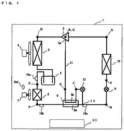
FIG. 1 is a schematic circuit configuration diagram illustrating an example of the circuit configuration of an air-conditioning apparatus according to Embodiment 1 of the present invention.
FIG. 2 is a refrigerant circuit diagram illustrating the flow of a refrigerant in a cooling operation mode of the air-conditioning apparatus according to Embodiment 1 of the present invention.
FIG. 3 is a refrigerant circuit diagram illustrating the flow of a refrigerant in a heating operation mode of the air-conditioning apparatus according to Embodiment 1 of the present invention.
FIG. 4 is a refrigerant circuit diagram illustrating the flow of a refrigerant in a low-outside-air-temperature heating operation mode of the air-conditioning apparatus according to Embodiment 1 of the present invention.
FIG. 5 is a refrigerant circuit diagram illustrating the flow of a refrigerant in a low-outside-air-temperature heating operation start mode of the air-conditioning apparatus according to Embodiment 1 of the present invention.
FIG. 6 is a flowchart illustrating a control operation in the low-outside-air-temperature heating operation start mode of the air-conditioning apparatus according to Embodiment 1 of the present invention.
FIG. 7 is a schematic circuit configuration diagram illustrating an example of the circuit configuration of an air-conditioning apparatus according to Embodiment 2 of the present invention.
FIG. 8 is a schematic circuit configuration diagram illustrating an example of the circuit configuration of an air-conditioning apparatus according to Embodiment 3 of the present invention.
Detailed description
Embodiment 1
Embodiments of the present invention will be described hereinafter with reference to the drawings.
FIG. 1 is a schematic circuit configuration diagram illustrating an example of the circuit configuration of an air-conditioning apparatus (to be referred to as an air-conditioning apparatus 100 hereinafter) according to Embodiment 1. A detailed configuration of the air-conditioning apparatus 100 will be described with reference to FIG. 1 . In the air-conditioning apparatus 100 , an outdoor unit 1 and an indoor unit 2 are connected to each other via main refrigerant pipes 4 , and a refrigerant circulates between them to allow air conditioning using a refrigeration cycle.
The air-conditioning apparatus 100 is an improved version that suppresses an increase in the temperature of the refrigerant discharged from a compressor while suppressing a reduction in user comfort, even when the outside air temperature is low.
[Outdoor Unit 1 ]
The outdoor unit 1 includes a compressor 10 having an injection port, a refrigerant flow switching device 11 such as a four-way valve, a heat source side heat exchanger 12 , an accumulator 13 for storing a surplus refrigerant, an oil separator 14 for separating refrigerating machine oil contained in the refrigerant, an oil return pipe 15 having its one side connected to the oil separator 14 and its other side connected to the suction side of the compressor 10 , a refrigerant heat exchanger 16 such as a double-pipe heat exchanger, and a first expansion device 30 , and these elements are connected to one another via the main refrigerant pipes 4 .
An injection pipe 18 is connected to the main refrigerant pipe 4 between the refrigerant heat exchanger 16 and the indoor unit 2 to be injected into an intermediate compression chamber in the compressor 10 , and a second expansion device 31 , the refrigerant heat exchanger 16 , and a first opening and closing device 32 are connected in series with the injection pipe 18 . A branching pipe 18 B through which a refrigerant is supplied to the refrigerant inlet side of the accumulator 13 is connected to the injection pipe 18 , and a second opening and closing device 33 is connected to the branching pipe 18 B. The second expansion device 31 and the injection pipe 18 are disposed in the outdoor unit 1 .
The outdoor unit 1 has a bypass pipe 17 for bypassing the discharge side of the compressor 10 and the suction side of the compressor 10 via the heat source side heat exchanger 12 during the heating operation. A third opening and closing device 35 for adjusting the flow rate is connected to the bypass pipe 17 .
The outdoor unit 1 is provided with a first temperature sensor 43 , a second temperature sensor 45 , and a third temperature sensor 48 to detect the temperatures of a refrigerant, a first pressure sensor 41 , a second pressure sensor 42 , and a third pressure sensor 49 to detect the pressures of the refrigerant, and a controller 50 to control the rotation speed and the like of the compressor 10 based on these pieces of detected information.
The compressor 10 is configured to draw by suction and compress a refrigerant to a high-temperature, high-pressure state, and is desirably implemented using, for example, a capacity-controllable inverter compressor or the like. The compressor 10 has its discharge side connected to the refrigerant flow switching device 11 via the oil separator 14 , and its suction side connected to the accumulator 13 . The compressor 10 has an intermediate compression chamber, and the injection pipe 18 is connected to the intermediate compression chamber.
The refrigerant flow switching device 11 is configured to switch between the flow of refrigerant in a heating operation mode and the flow of refrigerant in a cooling operation mode. In the cooling operation mode, the refrigerant flow switching device 11 performs switching so as to connect the discharge side of the compressor 10 and the heat source side heat exchanger 12 via the oil separator 14 and connect the accumulator 13 and the indoor unit 2 . In the heating operation mode, the refrigerant flow switching device 11 performs switching so as to connect the discharge side of the compressor 10 and the indoor unit 2 via the oil separator 14 and connect the heat source side heat exchanger 12 and the accumulator 13 .
The heat source side heat exchanger 12 functions as an evaporator during the heating operation and functions as a condenser during the cooling operation to exchange heat between the air supplied from an air-sending device (not illustrated) such as a fan and the refrigerant. The heat source side heat exchanger 12 has its one side connected to the refrigerant flow switching device 11 , and its other side connected to the first expansion device 30 . The heat source side heat exchanger 12 is further connected to the bypass pipe 17 so as to exchange heat between the refrigerant supplied from the bypass pipe 17 and the air supplied from the air-sending device such as a fan.
The accumulator 13 is disposed on the suction side of the compressor 10 , and is configured to accumulate a surplus refrigerant generated due to factors associated with the difference between the heating operation mode and the cooling operation mode or a surplus refrigerant generated in response to a transient change in operation. The accumulator 13 has its one side connected to the suction side of the compressor 10 , and its other side connected to the refrigerant flow switching device 11 .
The oil separator 14 is configured to separate a mixture of refrigerating machine oil and a refrigerant discharged from the compressor 10 . The oil separator 14 is connected to the discharge side of the compressor 10 , the refrigerant flow switching device 11 , and the oil return pipe 15 .
The oil return pipe 15 is configured to return the refrigerating machine oil to the compressor 10 , and the oil return pipe 15 is preferably partially implemented using a capillary tube or the like. The oil return pipe 15 has its one side connected to the oil separator 14 , and its other side connected to the suction side of the compressor 10 .
The refrigerant heat exchanger 16 is configured to exchange heat between refrigerants, and is implemented using, for example, a double-pipe heat exchanger or the like. The refrigerant heat exchanger 16 sufficiently ensures the degree of subcooling of the high-pressure refrigerant during the cooling operation, and is configured to adjust the quality of the refrigerant that is to flow into the injection port of the compressor 10 during a low-outside-air-temperature heating operation. The refrigerant heat exchanger 16 has its one refrigerant passage side connected to the main refrigerant pipe 4 connecting the first expansion device 30 and the indoor unit 2 , and its other refrigerant passage side connected to the injection pipe 18 .
The first expansion device 30 is configured to adjust the pressure of the refrigerant that is to flow into the heat source side heat exchanger 12 in the heating operation mode. The first expansion device 30 has its one side connected to the refrigerant heat exchanger 16 , and its other side connected to the heat source side heat exchanger 12 .
The second expansion device 31 is configured to adjust the pressure of the refrigerant that is to flow into the injection port of the compressor 10 during the low-outside-air-temperature heating operation. The second expansion device 31 has its one side connected to the main refrigerant pipe 4 connecting the refrigerant heat exchanger 16 and the indoor unit 2 , and its other side connected to the refrigerant heat exchanger 16 .
The first expansion device 30 and the second expansion device 31 each function as a pressure reducing valve or an expansion valve to reduce the pressure of a refrigerant to expand it. Each of the first expansion device 30 and the second expansion device 31 is preferably implemented using a device having a variably controllable opening degree, such as an electronic expansion valve.
The injection pipe 18 is configured to connect the main refrigerant pipe 4 connecting the indoor unit 2 and the refrigerant heat exchanger 16 to the compressor 10 . The injection pipe 18 is connected to the branching pipe 18 B. The branching pipe 18 B is provided with the second opening and closing device 33 , and has its one side connected to the main refrigerant pipe 4 on the refrigerant inlet side of the accumulator 13 , and its other side connected to the injection pipe 18 .
The injection pipe 18 is provided with the first opening and closing device 32 to adjust the flow rate. The first opening and closing device 32 is configured to adjust the amount of refrigerant that is to flow into the injection port of the compressor 10 , and the second opening and closing device 33 is configured to adjust the amount of refrigerant to be supplied to the inlet side of the accumulator 13 .
The injection pipe 18 , the refrigerant heat exchanger 16 , the second expansion device 31 , the first opening and closing device 32 , and the second opening and closing device 33 allow the air-conditioning apparatus 100 to “adjust the amount of refrigerant that is to flow into the injection port of the compressor 10 from the refrigerant heat exchanger 16 during the low-outside-air-temperature heating operation”, and further allow the air-conditioning apparatus 100 to “adjust the flow rate of the low-pressure refrigerant, ensure a desired degree of subcooling of the high-pressure refrigerant, and bypass the refrigerant to the inlet side of the accumulator 13 during the cooling operation”.
The bypass pipe 17 is connected so as to bypass the discharge side of the compressor 10 and the suction side of the compressor 10 via the heat source side heat exchanger 12 during the heating operation. More specifically, the bypass pipe 17 has its one side connected to the main refrigerant pipe 4 connecting the refrigerant flow switching device 11 and the indoor unit 2 , and its other side connected to the main refrigerant pipe 4 connecting the accumulator 13 and the suction side of the compressor 10 . The bypass pipe 17 is provided to extend through the heat source side heat exchanger 12 so as to allow it to exchange heat with the refrigerant flowing through the heat source side heat exchanger 12 .
The bypass pipe 17 is provided with the third opening and closing device 35 to adjust the amount of refrigerant. The third opening and closing device 35 is configured to adjust the flow of a high-pressure liquid having exchanged heat with the refrigerant flowing through the heat source side heat exchanger 12 , or a two-phase refrigerant, which is supplied to the suction side of the compressor 10 .
Each of the first opening and closing device 32 , the second opening and closing device 33 , and the third opening and closing device 35 is preferably implemented using a device capable of adjusting the opening degree of a refrigerant passage, such as, for example, a two-way valve, a solenoid valve, or an electronic expansion valve.
The first temperature sensor 43 is disposed in the main refrigerant pipe 4 connecting between the discharge side of the compressor 10 and the oil separator 14 , and is configured to detect the temperature of the refrigerant discharged from the compressor 10 . The second temperature sensor 45 is disposed in an air suction unit of the heat source side heat exchanger 12 , and is configured to measure the ambient air temperature of the outdoor unit 1 . The third temperature sensor 48 is disposed in the injection pipe 18 connecting between the refrigerant heat exchanger 16 and the first opening and closing device 32 , and is configured to detect the temperature of the refrigerant that has flowed into the injection pipe 18 and that has flowed out of the refrigerant heat exchanger 16 via the second expansion device 31 . Each of the first temperature sensor 43 , the second temperature sensor 45 , and the third temperature sensor 48 is preferably implemented using, for example, a thermistor or the like.
The first pressure sensor 41 is disposed in the main refrigerant pipe 4 connecting between the compressor 10 and the oil separator 14 , and is configured to detect the pressure of the high-temperature, high-pressure refrigerant compressed by and discharged from the compressor 10 . The second pressure sensor 42 is disposed in the main refrigerant pipe 4 connecting the indoor unit 2 and the refrigerant heat exchanger 16 , and is configured to detect the pressure of a low-temperature, intermediate-pressure refrigerant that flows into the first expansion device 30 . The third pressure sensor 49 is disposed in the main refrigerant pipe 4 connecting the refrigerant flow switching device 11 and the accumulator 13 , and is configured to detect the pressure of the low-pressure refrigerant.
The controller 50 is configured to control the overall operation of the air-conditioning apparatus 100 , and is implemented using a microcomputer or the like. The controller 50 controls, in accordance with pieces of information detected by various detecting means and an instruction issued by remote control, the driving frequency of the compressor 10 , the rotation speeds (including ON/OFF) of fans (not illustrated) used for the heat source side heat exchanger 12 and the use side heat exchanger 21 , the switching operation of the refrigerant flow switching device 11 , the opening degree of the first expansion device 30 , the opening degree of the second expansion device 31 , the opening degree of a third expansion device 22 , the opening/closing of the first opening and closing device 32 , the opening/closing of the second opening and closing device 33 , the opening/closing of the third opening and closing device 35 , and so forth to execute operation modes (to be described later). The controller 50 may be provided for each unit, or may be provided in either the outdoor unit 1 or the indoor unit 2 .
[Indoor Unit 2 ]
The indoor unit 2 is equipped with a use side heat exchanger 21 and a third expansion device 22 . The indoor unit 2 is further provided with a fourth temperature sensor 46 , a fifth temperature sensor 47 , and a sixth temperature sensor 44 to detect the temperatures of a refrigerant.
The use side heat exchanger 21 is connected to the outdoor unit 1 via the main refrigerant pipes 4 so that a refrigerant flows into or out of it. The use side heat exchanger 21 is configured to exchange heat between, for example, the air supplied from an air-sending device (not illustrated) such as a fan and the refrigerant to generate air for use in heating or air for use in cooling which is supplied to an indoor space.
The third expansion device 22 functions as a pressure reducing valve or an expansion valve to reduce the pressure of a refrigerant to expand it, and is disposed on the upstream side of the use side heat exchanger 21 in the flow of a refrigerant in the cooling operation mode. The third expansion device 22 is preferably implemented using a device having a variably controllable opening degree, such as an electronic expansion valve.
The fourth temperature sensor 46 is disposed in a pipe connecting between the third expansion device 22 and the use side heat exchanger 21 , and the fifth temperature sensor 47 is disposed in a pipe connecting the use side heat exchanger 21 and the refrigerant flow switching device 11 . The fourth temperature sensor 46 and the fifth temperature sensor 47 are configured to detect the temperature of a refrigerant that flows into the use side heat exchanger 21 or the temperature of a refrigerant that has flowed out of the use side heat exchanger 21 . The sixth temperature sensor 44 is disposed in an air suction unit of the use side heat exchanger 21 . Each of the fourth temperature sensor 46 , the fifth temperature sensor 47 , and the sixth temperature sensor 44 is preferably implemented using, for example, a thermistor or the like.
Although FIG. 1 illustrates the air-conditioning apparatus 100 that is provided with one indoor unit 2 , the embodiments herein are not limited to this configuration. That is, the air-conditioning apparatus 100 is provided with a plurality of indoor units 2 connected in parallel to the outdoor unit 1 , and is capable of selecting a “cooling operation mode in which all the indoor units 2 perform a cooling operation” or a “heating operation mode in which all the indoor units 2 perform a heating operation” (both will be described later).
The individual operation modes to be executed by the air-conditioning apparatus 100 will be described below. The air-conditioning apparatus 100 implements the cooling operation mode or the heating operation mode in accordance with an instruction from the indoor unit 2 . The individual operation modes will be described hereinafter in conjunction with the flow of a refrigerant.
[Cooling Operation Mode]
FIG. 2 is a refrigerant circuit diagram illustrating the flow of a refrigerant in a cooling operation mode of the air-conditioning apparatus 100 according to Embodiment 1. The cooling operation mode will be described with reference to FIG. 2 , assuming, for example, that a cooling load has been generated in the use side heat exchanger 21 . Referring to FIG. 2 , the direction in which a refrigerant flows is indicated by solid arrows.
In the cooling operation mode illustrated in FIG. 2 , a low-temperature, low-pressure refrigerant is compressed by the compressor 10 into a high-temperature, high-pressure gas refrigerant, which is then discharged. The high-temperature, high-pressure gas refrigerant discharged from the compressor 10 is separated by the oil separator 14 into a high-temperature, high-pressure gas refrigerant and refrigerating machine oil, and only the high-temperature, high-pressure gas refrigerant flows into the heat source side heat exchanger 12 via the refrigerant flow switching device 11 . The refrigerating machine oil separated by the oil separator 14 flows into the compressor 10 from its suction side via the oil return pipe 15 .
The high-temperature, high-pressure gas refrigerant that flows into the heat source side heat exchanger 12 becomes a high-pressure liquid refrigerant while transferring heat to the outdoor air from the heat source side heat exchanger 12 . The high-pressure refrigerant flowing out of the heat source side heat exchanger 12 flows into the refrigerant heat exchanger 16 via the first expansion device 30 , which is open to a nearly maximum degree. Then, the high-pressure refrigerant branches at the outlet of the refrigerant heat exchanger 16 into a high-pressure liquid refrigerant that flows out of the outdoor unit 1 and a high-pressure liquid refrigerant that flows into the second expansion device 31 .
Note that the high-pressure liquid refrigerant that flows out of the outdoor unit 1 transfers heat in the refrigerant heat exchanger 16 to a low-pressure, low-temperature refrigerant decompressed by the second expansion device 31 , and becomes a subcooled high-pressure liquid refrigerant as a result.
On the other hand, the high-pressure liquid refrigerant that flows into the second expansion device 31 is decompressed to a low-pressure, low-temperature refrigerant by the second expansion device 31 , then removes heat in the refrigerant heat exchanger 16 from the high-pressure liquid refrigerant flowing out of the first expansion device 30 , and becomes a low-pressure gas refrigerant as a result. The low-pressure gas refrigerant flows into the accumulator 13 via the second opening and closing device 33 . Since the first opening and closing device 32 is closed, the refrigerant is not injected into the compressor 10 .
The high-pressure liquid refrigerant flowing out of the outdoor unit 1 passes through the main refrigerant pipe 4 , and is expanded into a low-temperature, low-pressure two-phase refrigerant by the third expansion device 22 . The two-phase refrigerant flows into the use side heat exchanger 21 operating as an evaporator, removes heat from the indoor air, and, as a result, becomes a low-temperature, low-pressure gas refrigerant while cooling the indoor air. The gas refrigerant flowing out of the use side heat exchanger 21 passes through the main refrigerant pipe 4 , and flows into the outdoor unit 1 again. The refrigerant flowing into the outdoor unit 1 passes through the refrigerant flow switching device 11 and the accumulator 13 , and is drawn by suction into the compressor 10 again.
Note that the opening degree of the second expansion device 31 is controlled so that the degree of superheat, which is obtained as the difference between the refrigerant saturation temperature calculated from the pressure detected by the third pressure sensor 49 and the temperature detected by the third temperature sensor 48 , becomes constant. Furthermore, the opening degree of the third expansion device 22 is controlled so that the degree of superheat, which is obtained as the difference between the temperature detected by the fourth temperature sensor 46 and the temperature detected by the fifth temperature sensor 47 , becomes constant.
[Heating Operation Mode]
FIG. 3 is a refrigerant circuit diagram illustrating the flow of a refrigerant in a heating operation mode of the air-conditioning apparatus 100 according to Embodiment 1. This heating operation mode is executed when the outside air temperature is comparatively high (for example, 5 degrees C. or higher). Referring to FIG. 3 , the direction in which a refrigerant flows is indicated by solid arrows.
In the heating operation mode illustrated in FIG. 3 , a low-temperature, low-pressure refrigerant is compressed by the compressor 10 into a high-temperature, high-pressure gas refrigerant, which is then discharged. The high-temperature, high-pressure gas refrigerant discharged from the compressor 10 is separated by the oil separator 14 into a high-temperature, high-pressure gas refrigerant and refrigerating machine oil, and only the high-temperature, high-pressure gas refrigerant flows out of the outdoor unit 1 via the refrigerant flow switching device 11 . The refrigerating machine oil separated by the oil separator 14 flows into the compressor 10 from its suction side via the oil return pipe 15 .
The high-temperature, high-pressure gas refrigerant flowing out of the outdoor unit 1 passes through the main refrigerant pipe 4 , transfers heat in the use side heat exchanger 21 to the indoor air, and, as a result, becomes a liquid refrigerant while heating the indoor air. The liquid refrigerant flowing out of the use side heat exchanger 21 is expanded by the third expansion device 22 into a low-temperature, intermediate-pressure two-phase or liquid refrigerant, which passes through the main refrigerant pipe 4 and flows into the outdoor unit 1 again.
The low-temperature, intermediate-pressure two-phase or liquid refrigerant flowing into the outdoor unit 1 passes through the refrigerant heat exchanger 16 without heat exchange, and becomes a low-temperature, low-pressure gas refrigerant while removing heat in the heat source side heat exchanger 12 from the outdoor air via the first expansion device 30 , which is open to a nearly maximum degree. The low-temperature, low-pressure gas refrigerant is drawn by suction into the compressor 10 again via the refrigerant flow switching device 11 and the accumulator 13 .
In a normal heating operation mode, the second expansion device 31 is closed. Furthermore, the opening degree of the third expansion device 22 is controlled so that the degree of subcooling, which is obtained as the difference between the value of the saturation temperature corresponding to the pressure detected by the first pressure sensor 41 and the temperature detected by the fourth temperature sensor 46 , becomes constant.
[Low-Outside-Air-Temperature Heating Operation Mode]
FIG. 4 is a refrigerant circuit diagram illustrating the flow of a refrigerant in a low-outside-air-temperature heating operation mode of the air-conditioning apparatus 100 according to Embodiment 1. The low-outside-air-temperature heating operation mode is executed when the outside air temperature is comparatively low (for example, −10 degrees C. or less). Referring to FIG. 4 , the direction in which a refrigerant flows is indicated by solid arrows.
In the low-outside-air-temperature heating operation mode illustrated in FIG. 4 , a low-temperature, low-pressure refrigerant is compressed by the compressor 10 into a high-temperature, high-pressure gas refrigerant, which is then discharged. The high-temperature, high-pressure gas refrigerant discharged from the compressor 10 is separated by the oil separator 14 into a high-temperature, high-pressure gas refrigerant and refrigerating machine oil, and only the high-temperature, high-pressure gas refrigerant flows out of the outdoor unit 1 via the refrigerant flow switching device 11 . The refrigerating machine oil separated by the oil separator 14 flows into the compressor 10 from its suction side via the oil return pipe 15 .
The high-temperature, high-pressure gas refrigerant that has flowed out of the outdoor unit 1 passes through the main refrigerant pipe 4 , transfers heat in the use side heat exchanger 21 to the indoor air, and, as a result, becomes a liquid refrigerant while heating the indoor air. The liquid refrigerant flowing out of the use side heat exchanger 21 is expanded by the third expansion device 22 into a low-temperature, intermediate-pressure two-phase or liquid refrigerant, which passes through the main refrigerant pipe 4 and flows into the outdoor unit 1 again. The low-temperature, intermediate-pressure two-phase or liquid refrigerant flowing into the outdoor unit 1 branches at the inlet of the refrigerant heat exchanger 16 into a refrigerant that flows into the refrigerant heat exchanger 16 and a refrigerant that flows into the injection pipe 18 .
The refrigerant that has flowed into the refrigerant heat exchanger 16 on the side of the main refrigerant pipe 4 transfers heat to the refrigerant on the side of the injection pipe 18 , which is a low-temperature, low-pressure two-phase refrigerant decompressed by the second expansion device 31 , so as to be further cooled into a low-temperature, intermediate-pressure liquid refrigerant. Then, the low-temperature, intermediate-pressure liquid refrigerant further cooled in the refrigerant heat exchanger 16 flows into and is decompressed by the first expansion device 30 , and then becomes a low-temperature, low-pressure gas refrigerant while removing heat in the heat source side heat exchanger 12 from the outdoor air. The low-temperature, low-pressure gas refrigerant flowing out of the heat source side heat exchanger 12 is drawn by suction into the compressor 10 again via the refrigerant flow switching device 11 and the accumulator 13 .
On the other hand, the refrigerant that has flowed into the injection pipe 18 flows into and is decompressed by the second expansion device 31 into a low-temperature, low-pressure two-phase refrigerant. The low-temperature, low-pressure two-phase refrigerant then flows into the refrigerant heat exchanger 16 , removes heat from the low-temperature, intermediate-pressure two-phase or liquid refrigerant, and, as a result, becomes a low-temperature, low-pressure two-phase refrigerant having a slightly high quality and having a pressure higher than the intermediate pressure of the compressor 10 . The low-temperature, low-pressure two-phase refrigerant flowing out of the refrigerant heat exchanger 16 on the side of the injection pipe 18 is injected into the intermediate compression chamber in the compressor 10 via the first opening and closing device 32 .
Note that the opening degree of the first expansion device 30 is controlled so that the pressure detected by the second pressure sensor 42 becomes equal to a predetermined value (for example, approximately 1.0 MPa). The opening degree of the second expansion device 31 is controlled so that the degree of superheat, which is obtained as the difference between the value of the saturation temperature corresponding to the pressure detected by the first pressure sensor 41 and the temperature detected by the first temperature sensor 43 , becomes constant. The opening degree of the third expansion device 22 is controlled so that the degree of subcooling, which is obtained as the difference between the value of the saturation temperature corresponding to the pressure detected by the first pressure sensor 41 and the temperature detected by the fourth temperature sensor 46 , becomes constant.
[Effect of Low-Outside-Air-Temperature Heating Operation Mode]
Without injection into the compressor 10 , the refrigerant needs to remove heat from the low-temperature outside air in the heat source side heat exchanger 12 , and its evaporating temperature therefore reduces. Thus, the density of a refrigerant drawn by suction into the compressor 10 decreases.
If the density of a refrigerant drawn by suction into the compressor 10 decreases, the flow rate of the refrigerant in the refrigeration cycle decreases, making it difficult to ensure a sufficient heating capacity. Again, if the density of a refrigerant drawn by suction into the compressor 10 decreases, a dilute refrigerant is compressed and heated. Accordingly, the temperature of the refrigerant discharged from the compressor 10 significantly increases.
However, the air-conditioning apparatus 100 executes the low-outside-air-temperature heating operation mode after executing a low-outside-air-temperature heating operation start mode (to be described later), so that the reduction in the density of a refrigerant can reliably be suppressed to ensure a sufficient heating capacity and suppress an increase in the temperature of the discharged refrigerant.
The description continues in the full USPTO document.
 Lapsed, fee not paid2 drawings