 Lapsed, fee not paid4 drawings
Industrial Equipment · US 9,797,547 B2
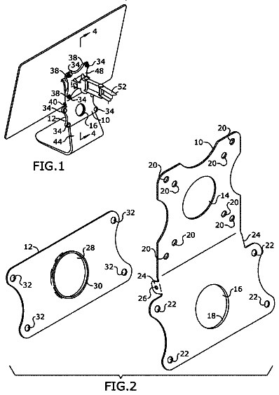
Computer and monitor mounting adapter
A mounting adapter for mounting a computer or monitor to a stand is provided.
US 9,797,629 B2 · Assignee: Fahrenheit AG · Inventors: Mittelbach; Walter
Sheet 1 of 2 from the published document. All sheets in the USPTO PDF
The invention relates to a method for carrying out a heat transfer between alternately working adsorbers (Ad 1 , Ad 2 ) in an adsorption refrigeration installation comprising an external cooling circuit (Kw) and an external heating circuit (Hw). The method is characterized by a closed heat transfer circuit, connected between the first and the second adsorber, comprising a heat transfer medium (Wm) circulating therein, a heat transfer with the external cooling circuit (Kw) being carried out in the heat transfer circuit via a first heat contact and a heat transfer with the external heating circuit (Hw) being carried out via a second heat contact.
1 of 2 drawing sheets so far from the published document, cropped to the drawing. Every sheet is in the USPTO PDF.
What the patent claimed, word for word. All of it is now free to use.
The invention relates to a method for carrying out a heat transfer between alternately working adsorbers in an adsorption refrigeration system according to the preamble of claim 1 and to a device for carrying out a heat transfer between alternately working adsorbers according to the preamble of the patent claims.
In adsorption refrigeration systems comprising alternately working adsorbers a heat transfer between the two adsorbers needs to be carried out in the course of the thermodynamic cyclic process taking place in the system. This is necessary in order to adjust the temperature in each of the two adsorbers for an upcoming adsorption and desorption process of the refrigerating fluid driven around, thereby proceeding to the respectively following sub-step of the cyclic process. In the systems known from the prior art a heating and a cooling circuit are used for this purpose. By means of a valve system the first and second adsorber are alternately flown through by the medium circulating in the heating and cooling circuit until the temperatures in the two adsorbers are equal.
Such a procedure involves serious drawbacks. Due to the circulation of the heating and cooling media in the external, frequently large-sized circuits a number of hydraulic side effects occur, such as pressure losses and pressure peaks, which limit the heat transfer capacity between the respective adsorber and the heating and cooling medium. This has direct consequences for the time of adjustment with respect to the temperature equality in both adsorbers, which becomes unreasonably high, which has a negative effect on the entire cooling capacity of the adsorption refrigeration system.
Moreover, two independent external circuits have to be connected alternately to both adsorbers. This involves a great physical effort and requires correspondingly dimensioned and, thus, expensive valve systems. Also, the alternate flow of the heating and cooling media through the adsorbers causes an undesired hydraulic mixing of the heating and cooling circuit. Thus, external heating and cooling circuits have to be disregarded in the project planning of the adsorption refrigeration system if these are flown through by different media. Hence, the fields of application of a conventional adsorption refrigeration system are limited.
Therefore, it is the object to provide a method for carrying out a heat transfer between alternately working adsorbers in an adsorption refrigeration system comprising an external cooling circuit and heating circuit, which is devoid of the aforementioned drawbacks. Specifically, a mixing of the media from the external circuits is to be avoided, and the times of adjustment with respect to the temperature equilibrium between both adsorbers are to be shortened, so that the efficiency of the system can be sustainably enhanced.
With regard to the method aspect the object is achieved with a method for carrying out a heat transfer between alternately working adsorbers in an adsorption refrigeration system, comprising an external cooling circuit and an external heating circuit according to the features of claim 1 , and with regard to the device aspect with a device according to the features of the patent claims. The respective dependent claims describe useful and advantageous embodiments of the method and the device.
The method according to the invention is characterized by a closed heat transfer circuit connected between the first and second adsorber, comprising a heat transfer medium circulating therein. A heat transfer with the external cooling circuit is carried out in the heat transfer circuit via a first heat contact and a heat transfer with the external heating circuit is carried out via a second heat contact.
As contrasted with the approach known from the prior art it is inventively provided that the external cooling and heating circuit are completely decoupled and separated from the adsorbers. Instead, a heat-transferring medium circulates in a heat transfer circuit through the adsorbers and exchanges thermal energy with the external circuits at points provided to this end.
Due to the size of the heat transfer circuit, which is thus basically reduced, and the limited quantity of the circulating heat-transferring medium associated therewith, the switching behavior is improved considerably when the heat transfer between the adsorbers is carried out, and is completely decoupled from the hydrodynamic conditions in the external circuits. This brings about short response times, less physical effort for the corresponding valve systems and, to a large extent, the avoidance of hydraulic side effects. Moreover, a mixing of the external circuits is precluded. Hence, they can be flown through actually by any media, provided that they meet the thermodynamic requirements of the adsorption refrigeration system.
Specifically, the heat transfer circuit includes the following sub-steps in a cyclic process:
In a first sub-step the heat transfer medium is heated in the second heat contact and enters the first adsorber. At the same time, the heat transfer medium exits the second adsorber and the medium is cooled in the first heat contact.
Thus, in this sub-step, thermal energy is withdrawn from and submitted to the external heating and cooling circuits. The heat transfer medium allows by means of its flow a thermal contact between the first and second adsorber and second and first heat contact, respectively, and thus the external heating and cooling circuit.
In a second sub-step the heat transfer medium is transferred between the first adsorber and the second adsorber. At the same time, the heat transfer medium is transferred from the first heat contact into the second heat contact.
This sub-step denotes the heat transfer between the two adsorbers. At the same time, the medium cooled in the first heat contact by thermal contact with the external cooling circuit flows into the second heat contact, where it is thermally contacted with the external heating circuit.
In a third sub-step the heat transfer medium is heated in the second heat contact and now enters the second adsorber. At the same time, the heat transfer medium exits the first adsorber and is cooled in the first heat contact.
Hence, the third sub-step substantially corresponds to the first sub-step, however, with the difference that the second adsorber is now thermally contacted with the second heat contact and thus with the external heating circuit, and the first adsorber with the first heat contact and thus with the external cooling circuit.
In a fourth sub-step the heat transfer medium is transferred between the second adsorber and the first adsorber. At the same time, the heat transfer medium is transferred from the first heat contact to the second heat contact.
Hence, the fourth sub-step corresponds to the second sub-step of the method. That is, by means of the heat transfer circuit in a cycle, on the one hand the first and on the other hand the second adsorber are thermally contacted with the external cooling and heating circuits, and both adsorbers are thermally contacted with each other in between, whereby they are always only flown through by a medium from a closed circuit.
In a particularly useful embodiment of the method the second heat contact is designed as an evaporator and the first heat contact is designed as a condenser. The heat transfer medium is evaporated in the evaporator, while it is condensed in the condenser.
During the first and third sub-step the heat transfer medium condenses when the heat transfer medium enters the second adsorber and the first adsorber, respectively. During the second and fourth sub-step, when the heat transfer medium is transferred between the first adsorber and the second adsorber, the heat transfer medium partially evaporates in one of the two adsorbers, while it condenses in the other adsorber.
On the whole, the heat exchange with the external circuits, in conjunction with the phase transitions in the evaporator and condenser taking place at the same time, increases the heat transfer capacity in the heat transfer circuit and, thus, the efficiency of the adsorption refrigeration machine considerably. At the same time, the duration of the heat recovery process between the two adsorbers, i.e. the length of time of the cyclic process performed in the heat transfer circuit, is reduced considerably. Above all, this is of major importance for fast switching adsorption refrigeration systems. Moreover, under these conditions, the heat transfer medium flows through the respective adsorbers in its vapor phase. This requires a considerably smaller physical effort for controlling the flow paths and brings about a far more uniform flow behavior, with which pressure peaks can be avoided.
Usefully, the heat transfer medium condensed in the condenser is collected in a condensate container interposed between the condenser and the evaporator. Thus, the flow of the heat transfer medium between the condenser and the evaporator can be controlled in an easy manner.
An advantage is the collection of the liquid heat transfer medium in the condensate container under the influence of gravity. Thus, no pumping means are necessary.
In one embodiment the first adsorber is replaced by a first heat exchanger and the second adsorber is replaced by a second heat exchanger, wherein an alternate evaporation of a refrigerant of the adsorption refrigeration system takes place in the first and second heat exchanger, with the heating circuit being replaced by the cooling circuit.
A device for carrying out a heat transfer between alternately working adsorbers in an adsorption refrigeration system comprising an external cooling circuit and an external heating circuit is inventively characterized by a heat pipe arrangement with a heat transfer medium circulating therein and thermally coupled to the external cooling circuit and the external heating circuit.
The heat pipe arrangement usefully comprises the following components: There are provided a first heat contact in thermal contact with the cooling circuit, a second heat contact connected to the first heat contact and in thermal contact with the heating circuit, a first valve unit between the first adsorber, the second adsorber and the second heat contact, and a second valve unit between the first adsorber, the second adsorber and the first heat contact.
The first heat contact is usefully designed as a condenser, the second heat contact as an evaporator. Additionally, in an advantageous embodiment, a condensate container interposed between the condenser and the evaporator is provided.
Usefully, a third valve is located between the condenser and the condensate container, and a fourth valve is located between the condensate container and the evaporator. Thus, it is possible to control the flow of the condensed heat transfer medium between the condenser, the condensate container and the evaporator.
The valve means realize the following, cyclically recurring valve states. In a first valve state there is an open connection between the evaporator and the first adsorber, an open connection between the second adsorber and the condenser, in a second valve state there is an open connection between the first adsorber and the second adsorber as well as an open connection between the condenser and/or the condensate container and the evaporator, in a third valve state there is an open connection between the evaporator and the second adsorber as well as an open connection between the first adsorber and the condenser, and in a fourth valve state the second valve state is reassumed.
In the first and third valve state, if the condensate container is provided, a connection between the condenser and the condensate container may be opened. Thus, the resultant condensed heat transfer medium can be collected and stored temporarily outside the condenser.
The first valve unit and/or the second valve unit are designed as a controllable three-way valve. In one embodiment the third valve may also be a controllable three-way valve.
The method and the device are now explained in more detail by means of embodiments. The accompanying FIGS. 1 and 2 serve illustration purposes. Like parts, or parts acting similarly, have like reference numbers. In the drawings:
FIG. 1 shows a heat pipe arrangement flown though by a heat transfer medium,
FIG. 2 shows an embodiment for a refrigerating medium driven around in the adsorption refrigeration system.
FIG. 1 shows a heat pipe arrangement flown through by a heat transfer medium between a first adsorber Ad 1 , a second adsorber Ad 2 , an external cooling circuit Kw and an external heating circuit Hw.
The heat pipe arrangement is thermally coupled to the external cooling circuit by a condenser Kd and to the external heating circuit by an evaporator Vd. There is provided a condensate container Kb, which initially collects the heat transfer medium liquefied in the condenser and subsequently transfers it to the evaporator.
A number of valve units serve to control the flow and realize the working process taking place in the heat pipe arrangement. A first valve unit V 1 controls the supply of the heat transfer medium from the evaporator Vd to the adsorbers Ad 1 and Ad 2 as well as the flow of the heat transfer medium between the two adsorbers Ad 1 and Ad 2 . A second valve unit V 2 controls the forwarding of the heat transfer medium from the adsorbers Ad 1 and Ad 2 to the condenser Kd as well as the flow of the medium between both adsorbers.
A third valve unit opens and closes a connection between the condenser Kd and the condensate container Kb and between the condensate container Kb and the evaporator Vd, respectively. A fourth valve unit finally opens and closes another connection between the condensate container and the evaporator.
In this example the valve units V 1 and V 2 are each designed as three-way valves, which are operated and switched by a non-illustrated control unit. Specifically, this may be accomplished electromechanically, pneumatically or also hydraulically.
In this example the third valve unit V 3 is designed as a three way valve, which is disposed on the top side of the condensate container Kb and controls both the inflow from the condenser Kd and the outflow of the medium to the evaporator Vd. Such a position of the valve unit V 3 is useful so as to obtain a self-regulating flow rate of the heat transfer medium from the condensate container to the evaporator. In the arrangement shown, the liquid medium in the condensate container is sucked off by the negative pressure caused by the evaporation of the medium in the evaporator, whereby the flow rate of the liquid medium between the condensate container and the evaporator is directly dependent on the evaporation rate of the medium in the evaporator. Like valve units V 1 and V 2 this valve unit, too, is operated by the control unit and can be switched electromechanically, pneumatically or also hydraulically.
The fourth valve unit V 4 ensures a direct forwarding of the liquid heat transfer medium from the condensate container to the evaporator. In this regard a configuration is useful in which the condenser Kd is disposed above the condensate container Kb and the latter above the evaporator Vd, or at least on the height level thereof. With such a configuration the liquid heat transfer medium can flow into the condensate container alone under the influence of gravity and, if necessary, fall down into the evaporator Vd.
The different work cycles of the heat pipe arrangement are predetermined by the positions of the valve units V 1 , V 2 , V 3 and V 4 , with three different positions being provided for valve units V 1 and V 2 and two different positions for valve units V 3 and V 4 .
With reference to the following representation of valve unit V 1 these are defined as follows:
In position V 1 - 1 the connection between the adsorber Ad 1 and the evaporator Vd is opened and the connection between the adsorber Ad 2 and the evaporator Vd is closed. In position V 1 - 2 the connection between the adsorber Ad 2 and the evaporator V is opened and the connection between the adsorber Ad 1 and the evaporator Vd is closed. In position V 1 - 3 the connection between the adsorbers Ad 1 and Ad 2 is opened and their connections to the evaporator Vd are closed.
The following valve positions are defined for valve unit V 2 :
In position V 2 - 1 the connection between the adsorber Ad 1 and the condenser Kd is opened and the connection between the adsorber Ad 2 and the condenser Kd is closed. In position V 2 - 2 the connection between the adsorber Ad 1 and the condenser Kd is closed and the connection between the adsorber Ad 2 and the condenser Kd is opened. In position V 2 - 3 the connection between the adsorbers Ad 1 and Ad 2 is opened and their connections to the condenser Kd are closed.
Valve unit V 3 can assume the following valve positions:
In position V 3 - 1 the connection between the condenser Kd and the condensate container Kb is opened and the connection between the condensate container Kb and the evaporator Vd is closed. In position V 3 - 2 of valve unit V 3 the connection between the condensate container Kb and the evaporator Vd is open and the connection between the condenser Kd and the condensate container Kb is closed.
Finally, the following valve positions are defined for valve unit V 4 :
In position V 4 - 1 the connection between the condensate container Kb and the evaporator Vd is opened. In position V 4 - 2 the connection between the condensate container Kb and the evaporator Vd is closed.
The valve positions described and the switching states of the valve units provided in the device, which are necessary in the individual steps of the working cycle, can of course be realized by a plurality of other valve constructions known to the person skilled in the art. The combination of the switch positions of the valve units V 1 to V 4 , which is exactly predefined in each sub-step, particularly allows a compact construction comprising all valves, in the form of a special valve or a valve module, which realizes the switch positions described and in which the aforementioned valve units are constructionally united.
With due regard to the above-defined valve positions the cyclic process taking place in the heat pipe arrangement is carried out, for example, as follows: In a first step a desorption of the heat transfer medium takes place in adsorber Ad 1 and an adsorption of the medium takes place in adsorber Ad 2 . The first valve unit V 1 is here in position V 1 - 1 , the second valve unit V 2 is in position V 2 - 2 , the third valve unit V 3 is in position V 3 - 1 and the fourth valve unit V 4 is in position V 4 - 2 . In thermal contact with the heating circuit Hw the heat transfer medium evaporates in the evaporator Vd and flows to adsorber Ad 1 where it condenses. At the same time, the medium evaporates in adsorber Ad 2 and flows to the condenser Kd where it condenses in thermal contact with the external cooling circuit Kw. The heat transfer medium liquefied in the condenser flows into the condensate container Kb, where it is collected. The first step is concluded when the adsorber Ad 1 has adopted a temperature T.sub.HAd1 prevailing in the evaporator and determined by the external heating circuit Hw and when the adsorber Ad 2 has adopted a temperature T.sub.KAd2 prevailing in the condenser and determined by the external cooling circuit Kw.
In the second step a heat recovery takes place between the adsorber Ad 1 and the adsorber Ad 2 . The first valve unit is here in position V 1 - 3 , the second valve unit is in position V 2 - 3 , the third valve unit is in position V 3 - 2 and the fourth valve unit is in position V 4 - 2 .
The adsorbers Ad 1 and Ad 2 are now directly connected with each other and are cut off from the evaporator Vd and the condenser Kd. A part of the heat transfer medium in adsorber Ad 1 evaporates and condenses in adsorber Ad 2 . As a consequence adsorbers Ad 1 and Ad 2 adopt a same temperature T.sub.G. The second step is concluded when the temperature T.sub.G is reached. At the same time, the liquid heat transfer medium collected in the condensate container Kb is conducted into the evaporator Vd.
In the third step a desorption takes place in adsorber Ad 2 and an adsorption takes place in adsorber Ad 1 . The first valve unit is here in position V 1 - 2 , the second valve unit is in position V 2 - 1 , the third valve unit is in position V 3 - 1 and the fourth valve unit is in position V 4 - 2 . The heat transfer medium entering the evaporator Vd from the condensate container Kb evaporates in thermal contact with the external heating circuit Hw and flows into the adsorber Ad 2 where it condenses. At the same time, the heat transfer medium evaporates in adsorber Ad 1 and flows into the condenser Kd where it condenses in thermal contact with the cooling circuit Kw. The condensed heat transfer medium flows into the condensate container Kb, where it is collected. This step is concluded when the adsorber Ad 2 has adopted the temperature T.sub.HAd2 prevailing in the evaporator Vd and, thus, in the heating circuit Hw and when the adsorber Ad 1 has adopted the temperature T.sub.KAd1 prevailing in the condenser Kd and determined by the cooling circuit Kw.
In the fourth step a heat recovery takes place between the adsorber Ad 2 and the adsorber Ad 1 . The first valve unit is here in position V 1 - 3 , the second valve unit is in position V 2 - 3 , the third valve unit is in position V 3 - 2 and the fourth valve unit is in position V 4 - 2 . The adsorbers Ad 2 and Ad 1 are now directly connected with each other and are cut off from the evaporator Vd and the condenser Kd. A part of the heat transfer medium in adsorber Ad 2 evaporates and condenses in adsorber Ad 1 . As a consequence adsorbers Ad 1 and Ad 2 adopt a same temperature T.sub.G. The fourth step is concluded when the temperature T.sub.G is reached. At the same time, the liquid heat transfer medium collected in the condensate container Kb is conducted into the evaporator Vd. Thus, the working cycle is closed and followed again by the first step.
During this process the temperature of the heat transfer medium in the adsorbers, the condenser and the evaporator is continuously sensed by means of temperature sensors and transmitted to a non-illustrated control unit, which outputs switching signals to the valve units as a result of an internal program run and effects the corresponding valve positions.
As can be concluded from the above-described step sequence the heat transfer between the heat transfer medium and the cooling circuit in the condenser Kd, the heating circuit in the evaporator Vd and in the adsorbers Ad 1 and Ad 2 is associated with a phase transition. The heat transfer medium circulates in the section of the heat pipe located between the adsorbers and the condenser and between the adsorbers and the evaporator, and also in the section located between the adsorbers, in a gaseous or vaporous state, and is in a liquid state exclusively in the relatively short section located between the condenser and the evaporator. This brings about a particularly little physical effort along with a minimum of switching times for switching the valve units V 1 and V 2 , while the fluid flow between the condenser Kd and the evaporator Vd takes place almost exclusively under the influence of gravity. Smaller valves can be used, along with a comparable thermal capacity. As the external hydraulic circuits Kw and Hw remain separated, pressure peaks in these circuits are completely avoided owing to the switching of valves.
The use of phase transitions in the heat transfer medium considerably reduces the duration of the heat recovery process between the adsorbers in the second and fourth steps of the working cycle. Above all, this is a great advantage in fast switching adsorption refrigeration machines. Moreover, the condenser Kd and the evaporator Vd can be designed and optimized with respect to their hydraulic properties, especially regarding a pressure loss, and their heat transfer capacities independently of the construction of the adsorbers. Here, especially a use of plate heat exchangers is appropriate.
FIG. 2 shows an embodiment suited for driving around a refrigerant Km in the adsorption refrigeration system. With respect to its construction the embodiment of a refrigeration circuit shown in the figure substantially corresponds to the heat pipe arrangement shown in FIG. 1 . However, in the present embodiment the previously mentioned adsorbers are replaced by two heat exchangers WT 1 and WT 2 which carry out an evaporation and condensation of the refrigerant Km and are thermally coupled to adsorbers Ad 1 and Ad 2 of the aforementioned arrangement. All other components and operation cycles in the cyclic process correspond to the aforementioned heat pipe arrangement according to FIG. 1 . However, in this embodiment the evaporator Vd of the refrigeration circuit is coupled to the cooling circuit Kw mentioned in FIG. 1 , while the condenser Kd of this embodiment is thermally coupled to the environment of the adsorption refrigeration system.
The type of the heat transfer medium in the embodiment according to FIG. 1 and of the refrigerant in the embodiment according to FIG. 2 depends on the exact conditions of use, especially on the temperatures present at the condenser and the evaporator and determined by the external circuits, and on the pressure prevailing inside the line as well as on the heat of evaporation of the media and the heating and refrigerating capacity at the evaporator and condenser and adsorbers and heat exchangers, respectively. A use of water as well as, for example, of ammonia or water-ammonia mixtures is also possible. This is to be taken into account within the framework of the competent action of the skilled person when planning the device and the method.
Additional embodiments arise from the competent action of the skilled person and are defined in the dependent claims.
Ad 1 first adsorber Ad 2 second adsorber Kb condensate container Kd condenser Km refrigerant V 1 first valve unit V 2 second valve unit V 3 third valve unit V 4 fourth valve unit Wm heat transfer medium WT 1 first heat exchanger WT 2 second heat exchanger
About 4,458 words. The USPTO PDF has it with every drawing.
Fees are due 3.5, 7.5 and 11.5 years after grant. This patent expired on October 24, 2025, so the fee marked "not paid" was the one that went unpaid.
METHOD FOR CARRYING OUT A HEAT TRANSFER BETWEEN ALTERNATELY WORKING ADSORBERS AND DEVICE
Filed Jun 2009 · published Jun 2011Method for carrying out a heat transfer between alternately working adsorbers and device
Filed Jun 2009 · granted Oct 2017Earlier publications, parents and continuations. None of them can still be enforced, or this patent would not be listed.
Prior art cited by the examiner or applicant. Useful when you check your own idea for novelty.
Everything on this page comes from the documents linked above.


