Technical field
The present invention relates to a recording material containing a compound in which a dye is bonded to a polymer compound, and an optical information recording medium comprising a recording layer which contains this recording material and an intermediate layer adjacent to the recording layer.
Background art
As an optical information recording medium comprising recording layers and intermediate layers, for example, JP2012-89195A teaches that the recording layers contain a polymer binder and a dye dispersed in the polymer binder and that the dye absorbs a recording beam and generates heat to thereby cause the polymer binder to undergo a change in shape due to the generated heat, so that a protrusion sticking out from the recording layer into the intermediate layer is formed, whereby information is recordable in the optical information recording medium. JP2012-89195A also teaches an optical information recording medium comprising a large number of recording layers each of which preferably includes a multi-photon absorption dye as a dye in order to minimize influence on an adjacent recording layer at the time of recording or reading information.
Summary of the invention
In the optical information recording medium, it is desirable that the performance for recording and/or reading information can be maintained even after a long-term storage of the medium and that the shape (information) formed by irradiation of a recording beam is highly stable. However, for example, in the conventional optical information recording medium in which the dye is merely dispersed in the polymer binder, the dye may disadvantageously spread into the intermediate layer with the lapse of time. If the dye spreads into the intermediate layer, reflection of a light beam will become unlikely to occur at the interface between the recording layer and the intermediate layer, so that the performance for recording and/or reading information may be degraded.
Further, in the case where the recording layer contains a multi-photon absorption dye, an ultrashort-pulse laser with a large peak power is required for recording information. This leads to a problem such as an increase in the cost of an optical information recording apparatus. It is therefore desirable to provide an optical information recording medium in which a laser having a small peak power, such as a semiconductor laser, as used for a conventional optical recording can be used for recording.
With the foregoing drawbacks of the prior art in view, it is an object of the present invention to provide a recording material and an optical information recording medium, which excel in long-term stability and which allow information to be recorded using a laser having a small peak power.
In order to achieve the aforementioned object, there is provided a recording material comprising a dye-bonded polymer compound which contains a polymer compound to which a one-photon absorption dye is bonded, wherein a glass transition temperature of the recording material is higher than 200° C.
Since this material contains a compound in which a one-photon absorption dye is bonded to a polymer compound (hereinafter referred to as a “dye-bonded polymer compound”), spreading of the dye from a layer made of this material into an adjacent layer can be suppressed, so that the stability of the intensity of the beam reflected at the interface can be enhanced. Accordingly, for example, the performance for recording and/or reading information and the performance of an optical element of this recording material can be maintained. Further, since the above material is thermally stable because of its glass transition temperature higher than 200° C., deformation of the shape that has been formed by irradiation with a light beam can be suppressed to thereby enhance the stability of the shape. Furthermore, since the above material contains a one-photon absorption dye, information can be recorded using a laser having a small peak power.
In this description, the “recording material” is not limited to a material used for manufacture of an optical information recording medium and includes any material by which a shape formed by irradiation with a light beam can be retained (i.e., the shape can be recorded).
In the above-described recording material, it is preferable that a main chain of the polymer compound is selected from the group consisting of polyacenaphthylene, poly(N-vinylcarbazole), poly(N-vinylphthalimide), polyindene, and poly(N-trichlorophenyl maleimide).
Further, in the above-described recording material, it is preferable that the one-photon absorption dye is selected from the group consisting of 1-aminobutadiene derivatives, benzotriazole derivatives and acridone derivatives.
In the above-described recording material, the dye-bonded polymer compound, by way of example, has absorption maximum at a wavelength in the range from 300 nm to 400 nm and does not have absorption of light in a visible spectrum range of wavelengths equal to or greater than 450 nm.
With this configuration, for example, in the case where the recording material is used for an optical information recording medium, information can be recorded by a light beam having a wavelength approximately in the 300 to 400 nm range (e.g., 405 nm) and tracking servo control performed during recording and/or reading information can be carried out using a light beam in the visible spectrum range of wavelengths equal to or greater than 450 nm (e.g., 650 nm). This makes it possible to record and/or read information using a semiconductor laser used for the conventional optical information recording.
Further, in order to achieve the aforementioned object, there is provided an optical information recording medium comprising a recording layer and an intermediate layer adjacent to the recording layer, wherein the recording layer comprises the above-described recording material.
With this configuration, since the recording layer comprises the above-described recording material, spreading of the dye from the recording layer into the intermediate layer can be suppressed, so that the stability of the intensity of the beam reflected at the interface can be enhanced. Accordingly, the performance for recording and/or reading information can be maintained. Further, since the above configuration is thermally stable because of the glass transition temperature of the recording material that is higher than 200° C., deformation of the shape that has been formed by irradiation with a light beam can be suppressed to thereby enhance the stability of the shape. Furthermore, since in the above configuration the dye contains a one-photon absorption dye, information can be recorded using a laser having a small peak power.
In the above-described optical information recording medium, the recording layer may be provided in a plurality of layers of the optical information recording medium, and the intermediate layer may be provided between adjacent recording layers.
This makes it possible to achieve a large storage capacity of the optical information recording medium.
In the above-described optical information recording medium, each recording layer may have a first interface and a second interface between the recording layer and two intermediate layers sandwiching the recording layer, and at least one of the first and second interfaces may be configured to deform by heat generated by the one-photon absorption dye absorbing the recording beam to form a protrusion sticking out into at least one of the intermediate layers, whereby information is recorded.
With this configuration, since information can be recorded with a relatively small energy, recording of information at high sensitivity cab be performed.
The above-described optical information recording medium may be configured such that the protrusion is formed in one of the first interface and the second interface by irradiation with the recording beam and the protrusion is not formed in the other one of the first interface and the second interface. In this instance, it is preferable that a difference between refractive indices of the intermediate layer and the recording layer is greater at the interface in which the protrusions is formed than at the interface in which the protrusion is not formed.
With this configuration, the interface in which the protrusion is formed is used for reading the information; for this purpose, the difference between refractive indices of the materials is large at both sides of this interface so that the interface reflectivity becomes relatively large and thus information can be read out easily. In contrast, the interface in which the protrusion is not formed is not used for reading the information; for this reason, the transmittance for a light beam used for recording or reading information (hereinafter referred to as a “recording/reading beam”) (i.e., the total transmittance of the first interface and the second interface) can be increased by reducing the difference between refractive indices of the materials at both sides of the interface. Accordingly, in the case of multi-layered recording layers, the light beam can reach far deeper recording layers from the recording/reading beam radiation side. This is advantageous for increasing the storage capacity by increasing the number of recording layers.
In the above-described optical information recording medium, it is preferable that the difference between the refractive index of the intermediate layer forming the interface in which the protrusion is not formed and the refractive index of the recording layer is equal to or smaller than 0.05.
With this configuration, substantially no reflection of light occurs at the interface in which the protrusion is not formed, and in the case of multi-layered recording layers, the light beam can reach far deeper recording layers. This is advantageous for increasing the storage capacity by increasing the number of recording layers.
Brief description of the drawings
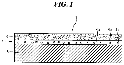
FIG. 1 is a diagram illustrating an optical information recording medium according to one embodiment.
FIG. 2 is a sectional view of the optical information recording medium.
FIG. 3 is a diagram illustrating a recording mark formed at the time of recording information.
FIG. 4 is a diagram explaining the operation at the time of reading the information.
FIG. 5 is a table for comparing properties of the optical information recording medium according to Example and properties of the optical information recording media according to Comparative Examples.
FIG. 6 is a table showing examples of a dye-bonded polymer compound.
Description of embodiments
One embodiment of the present invention will be described with reference to the drawings.
As seen in FIG. 1 , an optical information recording medium 10 according to one embodiment of the present invention takes a circular plate shape, and in order to prevent the optical information recording medium 10 from being damaged or soiled due to fall or handling as well as to improve the light fastness, the optical information recording medium 10 is stored in a cartridge case 20 .
As seen in FIG. 2 , the optical information recording medium 10 includes a substrate 11 , a reflective layer 12 , a spacer layer 13 , a plurality of recording layers 14 , a plurality of intermediate layers 15 (adhesive agent layers 15 A and recording layer support layers 15 B), a cover layer 16 , and a hard coat layer 17 . In this embodiment, an interface formed between a recording layer 14 and an adhesive agent layer 15 A is referred to as a recording interface 18 A as an example of a first interface, and an interface formed between a recording layer 14 and a recording layer support layer 15 B is referred to as a non-recording interface 18 B as an example of a second interface.
The substrate 11 is a support member for supporting the recording layers 14 , the intermediate layers 15 , and other layers. As an example, the substrate 11 is a circular plate made of polycarbonate. In the present invention, the material of the substrate 11 is not specifically limited. It is preferable that the substrate 11 has a thickness in the range of 0.02-2 mm. Further, the substrate 11 according to this embodiment has asperities (servo signal) which functions as a guide for tracking servo on the surface where a recording/reading beam is incident (upper-side surface in the drawing), and therefore the substrate 11 also functions as a guide layer 11 A. The guide layer 11 A may be a layer where the servo signal has been recorded, for example, by utilizing a change in the refractive index. Further, the guide layer 11 A may be provided as a separate layer from the substrate 11 .
The reflective layer 12 is a layer for reflecting the servo beam and consists of an aluminum thin film evaporated onto the uneven surface of the substrate 11 (guide layer 11 A). Providing the reflective layer 12 makes it possible to detect the servo signal at the incident side of the servo beam, and therefore the structure of the reading apparatus can be simplified.
The spacer layer 13 is a layer for adjusting the distance between the recording layer 14 and the guide layer 11 A and made of a material such as thermoplastic resin, thermosetting resin, ultraviolet curable resin, and adhesive. Preferably, the spacer layer 13 has a thickness in the range of 5-100 μm. Providing the spacer layer 13 makes it possible to reduce the likelihood that light reflected by the guide layer 11 A affects the recording layer 14 nearest to the guide layer 11 A.
The recording layer 14 is a layer made of a light-sensitive recording material on which information is optically recorded; the recording material contains a compound (dye-bonded polymer compound) in which a one-photon absorption dye for absorbing a recording beam is covalently bonded to a polymer binder as an example of a polymer compound.
The polymer binder to which the one-photon absorption dye is bonded may include, for example, a polymer binder containing a main chain that is selected from the group consisting of polyacenaphthylene, poly(N-vinylcarbazole), poly(N-vinylphthalimide), polyindene, and poly(N-trichlorophenyl maleimide). Chemical structural formulae of the monomers from which the above-described polymer binders are formed are shown below.
##str00001##
In the above chemical structural formulae, monomer 1-1 is acenaphthylene, monomer 1-2 is N-vinylcarbazole, monomer 1-3 is N-vinylphthalimide, monomer 1-4 is indene, and monomer 1-5 is N-trichlorophenyl maleimide.
The one-photon absorption dye for absorbing the recording beam may include, for example, dyes which have been conventionally used as a thermally deformable heat mode type recording material. Specific examples of the dyes may include methine dyes (cyanine dyes, hemicyanine dyes, styryl dyes, oxonol dyes, merocyanine dyes, etc.), large ring dyes (phthalocyanine dyes, naphthalocyanine dyes, porphyrin dyes, etc.), azo dyes (including azo-metal chelate dyes), arylidene dyes, complex dyes, coumarin dyes, azole derivatives, triazine derivatives, benzotriazole derivatives, benzophenone derivatives, phenoxazine derivatives, phenothiazine derivatives, 1-aminobutadiene derivatives, cinnamic acid derivatives, acridone derivatives, quinophthalone dyes, etc. Of these dyes, it is preferable that the one-photon absorption dye is selected from 1-aminobutadiene derivatives, benzotriazole derivatives and acridone derivatives. Examples for each of 1-aminobutadiene derivatives, benzotriazole derivatives and acridone derivatives are shown below.
##str00002##
In the above chemical structural formulae, monomer 2-1 is an example of 1-aminobutadiene derivatives, monomer 2-2 is an example of benzotriazole derivatives, and monomer 2-3 is an example of acridone derivatives.
As the dye-bonded polymer compound in which the one-photon absorption dye is bonded to the polymer binder, for example, compound G of the following chemical structural formula may be used. The compound G of this chemical structural formula includes polyacenaphthylene as the main chain of the polymer binder and 1-aminobutadiene derivative as the one-photon absorption dye. It is noted that when 1-aminobutadiene derivatives is used as the one-photon absorption dye, the recording sensitivity can be enhanced. Further, it is noted that when polyacenaphthylene is used as the main chain of the polymer binder, the liquid in which the recording material has been dissolved in a solvent is easily coated and the coated liquid is easily smoothed, so that the productivity of the recording layer 14 and the optical information recording medium 10 can be improved. Further, because polyacenaphthylene has a relatively high refractive index, the difference in refractive index becomes large between the recording layer 14 and the intermediate layer 15 (adhesive agent layer 15 A), so that the intensity of the beam reflected at the recording interface 18 A can be enhanced.
##str00003##
By way of example, the dye-bonded polymer compound is a compound which has absorption maximum at a wavelength in the range from 300 nm to 400 nm and does not have absorption in a visible spectrum range of wavelengths equal to or greater than 450 nm. By this dye-bonded polymer compound, for example, information can be recorded using a light beam having a wavelength of 405 nm and tracking servo performed during recording and/or reading information can be carried out using a light beam having a wavelength of 650 nm. This makes it possible to record and/or read information using a semiconductor laser used for the conventional optical information recording. The compound G of the above-described chemical structural formula has absorption maximum at a wavelength at or around 373 nm and does not have absorption at wavelengths in the range of 650±100 nm (wavelength of the light beam used for tracking servo), namely, at wavelengths in the range of 550 nm to 750 nm.
Further, the dye-bonded polymer compound preferably has a molecular weight Mw equal to or greater than 5,000, and more preferably equal to or greater than 8,000.
The recording material containing the above-described dye-bonded polymer compound in which the one-photon absorption dye is covalently bonded to the polymer binder has a glass transition temperature higher than 200° C. Therefore, the recording layer 14 containing this recording material is a thermally stable layer.
The recording layer 14 is a layer for recording dotted recording marks M (information) and configured such that when it is irradiated with a recording beam, the one-photon absorption dye absorbs the recording beam and generates heat, and the generated heat causes the polymer binder to undergo a change in shape to thereby cause the recording interface 18 A to stick out into the intermediate layer 15 (adhesive agent layer 15 A) to form protrusions. For this reason, each recording layer 14 is thicker than the conventional recording layer containing a polymer binder and a dye, and the thickness of one recording layer 14 is preferably not less than 50 nm. If the thickness is less than 50 nm, the interface between the recording layer and the intermediate layer (corresponding to the recording interface 18 A or the non-recording interface 18 B in this embodiment) deforms such that a recessed shape is formed with reference to the recording layer as observed before undergoing a change in shape (i.e., the recording layer is recessed partially into the intermediate layer). On the contrary, if the thickness is not less than 50 nm, the interface deforms such that a protrusion is formed at a center of the recorded spot. Although the thickness of the recording layer 14 does not have a determinate upper limit, it is preferable that the thickness thereof is not more than 5 μm in order to provide as many recording layer 14 as possible. To be more specific, the thickness of the recording layer 14 is more preferably in the range of 100 nm to 3 μm, and further preferably in the range of 200 nm to 2 μm. As an example, the thickness of the recording layer 14 is 0.5 μm in this embodiment.
According to the present invention, a recording mark M may include a center portion having a protrusion sticking out from the recording layer 14 into the adhesive agent layer 15 A, and the protrusion may be surrounded by a recess which is recessed from the adhesive agent layer 15 A into the recording layer 14 (a recessed shape recessed from a position of the recording interface 18 A before undergoing a change in shape).
A plurality of recording layers 14 are provided, and the number of recording layers 14 provided is, for example, approximately in the range of 2-100 layers. To increase the storage capacity of the optical information recording medium 10 , a large number of recording layers 14 , for example, 10 or more recording layers 14 are preferable. This can serve to achieve high-capacity recording of the optical information recording medium 10 . Further, the recording layer 14 is made of a material of which the refractive index substantially does not change before and after recording performed by changing the shape of the recording interface 18 A.
It is preferable that the recording layer 14 has an absorptance (of one-photon absorption dye) to the recording beam not more than 10% per one layer. Further, in order to increase the number of recording layers 14 , it is preferable that the absorptance of each recording layer is as small as possible as long as recording can be performed. Therefore, it is preferable that the absorptance of the recording layer 14 is not more than 8%, more preferably not more than 5%, and further preferably not more than 3%. This is because, for example, if the intensity of the recording beam which reaches the farthermost recording layer 14 has to be equal to or more than 50% of the intensity of the radiated recording beam, it is necessary that the absorptance per one recording layer is equal to or less than 8% in order to obtain eight recording layers, and that the absorptance per one recording layer is equal to or less than 3% in order to obtain twenty recording layers. If the absorptance is higher, the number of recording layers should be smaller; this lessens the effect of increasing the recording capacity by increasing the number of recording layers.
The dye-bonded polymer compound contained in the recording layer 14 preferably comprises the one-photon absorption dye of less than 50 mass % of the polymer binder. In other words, it is preferable that the content in mass percentage of the polymer binder is equal to or more than 50 mass % (i.e., the polymer binder is the main component). By this dye-bonded polymer compound, a sufficient height (amount of protrusion) of the protrusion (recording mark M) can be formed with reference to the recording interface 18 A before undergoing a change in shape. When the recording layer 14 is irradiated with the recording beam, the polymer binder undergoes a thermal expansion by absorption of the recording beam, thereafter the irradiation of the recording beam is stopped and the acquired expanded shape is maintained by quenching, to thereby form a protrusion. Therefore, if the content in mass percentage of the one-photon absorption dye is equal to or more than 50 mass % (i.e., the content in mass percentage of the polymer binder is less than 50 mass %), for example, the material of the polymer binder (which undergoes a thermal expansion by absorption of the recording beam) outflows and spills outside the expanded portion, with the result that formation of a protrusion is less likely to occur.
The recording layer 14 may be formed by any conventional method; for example, the dye-bonded polymer compound may be dissolved in a solvent, followed by spin coating or blade coating with the obtained liquid to form a recording layer 14 . Examples of the solvent may include dichloromethane, chloroform, methyl ethyl ketone (MEK), acetone, methyl isobutyl ketone (MIBK), toluene, hexane, propyleneglycol monomethylether acetate (PGMEA) and cyclohexanone.
The intermediate layers 15 are provided between the recording layers 14 , in other words, each intermediate layer 15 is provided adjacently above and below the recording layer 14 as shown in the drawing. To be more specific, the intermediate layer 15 includes an adhesive agent layer 15 A and a recording layer support layer 15 B, which are alternately arranged between the recording layers 14 . In other words, one recording layer 14 is sandwiched between the adhesive agent layer 15 A and the recording layer support layer 15 B; in this embodiment, the adhesive agent layer 15 A, the recording layer 14 , the recording layer support layer 15 B, and the recording layer 14 are repeatedly arranged in this order as viewed from the substrate 11 side.
In order to prevent crosstalk across a plurality of recording layers 14 , the intermediate layer 15 is provided to from a predetermined amount of space between the adjacent recording layers 14 . For this purpose, it is preferable that the thickness of the intermediate layer 15 is not less than 2 μm, and more preferably not less than 5 μm. Further, as long as the crosstalk can be prevented, it is preferable that the thickness of the intermediate layer 15 is as small as possible, such as 20 μm or less. In this embodiment, the thickness of the intermediate layer 15 (i.e., adhesive agent layer 15 A and recording layer support layer 15 B) is 10 μm each as an example. Since the thickness of the adhesive agent layer 15 A and the thickness of the recording layer support layer 15 B are the same, namely 10 μm, the recording interface 18 A have non-constant pitches of 10 μm, 11 μm, 10 μm, 11 μm . . . . This can reduce the likelihood that the interference between a readout beam (i.e., the beam reflected at the recording interface 18 A to be generated upon reading information) and a reflected beam of a reading beam (i.e., the reflected beam of the reading beam generated at a recording interface 18 A that is adjacent to the recording interface 18 A used for reading the information) affects the readout beam.
The intermediate layers 15 are made of materials which are unreactive to irradiation with a laser beam at the time of recording and reading out the information. Further, in order to minimize the loss of the recording beam, the reading beam, and the readout beam (light including a readout signal generated by irradiation with the reading beam), it is preferable that each of the intermediate layers 15 is made of a material which does not substantially absorb the recording beam, the reading beam, and the readout beam, in other words, a material which is transparent to the recording beam, the reading beam, and the readout beam. Herein, the term “transparent” indicates that the absorptance is not more than 1%.
The adhesive agent layer 15 A has adhesiveness to enable attachment to another surface and is softer than the recording layer 14 . For example, the glass transition temperature of the adhesive agent layer 15 A is lower than that of the recording layer 14 . On the other hand, the recording layer support layer 15 B is made of a material such as ultraviolet curable resin and is harder than the adhesive agent layer 15 A. For example, the recording layer support layer 15 B has a glass transition temperature higher than that of the adhesive agent layer 15 A.
As described above, the adhesive agent layer 15 A is used as the intermediate layer 15 that is adjacent to one side of the recording layer 14 , and the recording layer support layer 15 B harder than the adhesive agent layer 15 A is used as the intermediate layer 15 that is adjacent to the other side of the recording layer 14 , and thus when the recording layer 14 is heated, and caused to expand, by irradiation with the recording beam, the recording layer 14 deforms toward the adhesive agent layer 15 A that is the softer one of the intermediate layers 15 sandwiching the recording layer 14 (i.e., the adhesive agent layer 15 A and the recording layer support layer 15 B) to form a protrusion in the recording interface 18 A. Accordingly, the optical information recording medium 10 in this embodiment is configured such that when the recording layer 14 is irradiated with the recording beam, no protrusion is formed in the non-recording interface 18 B which is the interface between the recording layer 14 and the recording layer support layer 15 B but a protrusion (recording mark M) is formed in the recording interface 18 A which is the interface between the recording layer 14 and the adhesive agent layer 15 A.
To compare the hardnesses of the recording layer 14 , the adhesive agent layer 15 A and the recording layer support layer 15 B, the materials used for forming the recording layer 14 , the adhesive agent layer 15 A and the recording layer support layer 15 B are made into bulk bodies, which are then pressed to each other. To be more specific, when the bulk bodies are pressed to each other, it can be checked that the softer one will be recessed more deeply than the harder one.
The adhesive agent layer 15 A and the recording layer support layer 15 B have different refractive indices, but the recording layer support layer 15 B and the recording layer 14 have the same refractive index. Herein, “having the same refractive index” indicates that the two refractive indices are substantially the same. To be more specific, the recording layer 14 and the recording layer support layer 15 B have comparative refractive indices such that ((n 3 −n 1 )/(n 3 +n 1 )).sup.2≦0.0003 is satisfied, where n 1 represents the refractive index of the recording layer 14 , and n 3 represents the refractive index of the recording layer support layer 15 B, that is, the reflectivity at the non-recording interface 18 B is not more than 0.0003.
To prevent reflection at the interface (non-recording interface 18 B) between the recording layer 14 and the recording layer support layer 15 B, it is preferable that the refractive indices of the recording layer 14 and the recording layer support layer 15 B are as close as possible and that the difference between the refractive indices of the recording layer 14 and the recording layer support layer 15 B is preferably not more than 0.05, more preferably not more than 0.03, further preferably not more than 0.01, and most preferably 0. As an example, if the refractive index n 1 of the recording layer 14 is 1.565 and the refractive index n 3 of the recording layer support layer 15 B is 1.564, ((n 3 −n 1 )/(n 3 +n 1 )).sup.2 is almost 0.
On the contrary, the refractive indices of the adhesive agent layer 15 A and the recording layer 14 are different from each other to some appropriate degree. Accordingly, the refractive index rapidly changes at the interface (recording interface 18 A) between the recording layer 14 and the adhesive agent layer 15 A, so that the reading beam can be reflected. To be more specific, it is preferable that the difference between the refractive indices of the adhesive agent layer 15 A and the recording layer 14 is greater than the difference between the refractive indices of the recording layer support layer 15 B and the recording layer 14 and is not more than 0.11. To be more specific, the refractive indices of the recording layer 14 and the adhesive agent layer 15 A are different from each other to some appropriate degree such that the following relation is satisfied: 0.0005<(( n 2− n 1)/( n 2+ n 1)).sup.2≦0.04 where n 2 represents the refractive index of the adhesive agent layer 15 A, that is, the reflectivity at the recording interface 18 A is not less than 0.0005 and not more than 0.04.
If the reflectivity is not less than 0.0005, the quantity of the reflected beam reflected at the reflective interface 18 A is large, so that a high signal-to-noise ratio is obtained at the time of reading the information. Further, if the reflectivity is not more than 0.04, the quantity of the reflected beam reflected at the reflective interface 18 A is restricted to an appropriately small degree, so that the recording/reading beam can reach far deeper recording layers 14 without considerable attenuation upon recording and reading out the information. This makes it possible to achieve high storage capacity of the optical information recording medium 10 by providing a large number of recording layers 14 . As an example, if the refractive index n 1 of the recording layer 14 is 1.565 and the refractive index n 2 of the adhesive agent layer 15 A is 1.477, ((n 2 −n 1 )/(n 2 +n 1 )).sup.2 is approximately 0.0008.
As described above, the refractive indices of the recording layer 14 and the intermediate layer 15 can be adjusted to enhance the total transmittance of the recording interface 18 A and the non-recording interface 18 B; therefore, in the case of multi-layered recording layers, the light beam can reach far deeper recording layers 14 from the recording/reading beam radiation side. This is advantageous for increasing the storage capacity by increasing the number of recording layers. Especially in this embodiment, since the refractive index of the recording layer support layer 15 B and the refractive index of the recording layer 14 are substantially the same (the difference between the refractive indices is not more than 0.05), the light reflectivity at the non-recording interface 18 B is substantially zero, so that the light beam can reach far deeper recording layers 14 . This is advantageous for increasing the storage capacity by increasing the number of recording layers.
In order to adjust the refractive indices of the recording layer 14 and the intermediate layer 15 , the composition of the material for the recording layer 14 and the composition of the material for the intermediate layer 15 can be adjusted. To be more specific, since the material for the recording layer 14 (recording material) contains a dye-bonded polymer compound in which a one-photon absorption dye is bonded to a polymer binder, the polymer binder or the dye may be selectively adjusted to have an appropriate refractive index and to vary the composition ratio, whereby the refractive index of the recording layer 14 can be adjusted as desired. The refractive index of the polymer binder varies depending on the degree of polymerization even if they have similar basic components. For this reason, the refractive index of the recording layer 14 can also be adjusted using polymer binder with different degrees of polymerization or by adjusting the degree of polymerization of the polymer binder. Further, the refractive index of the recording layer 14 can be adjusted by mixing a plurality of polymer binders. Further, a refractive index matching material (inorganic particulate and the like) may be added to adjust the refractive index of the recording layer 14 .
To adjust the refractive index of the intermediate layer 15 , the degree of polymerization of the polymer material such as resin usable as the material for the intermediate layer 15 may be adjusted. Further, to adjust the refractive index of the intermediate layer 15 , a material usable for the intermediate layer 15 may be added as desired or a refractive index matching material (inorganic particulate and the like) may be added.
The cover layer 16 is a layer for protecting the recording layers 14 and the intermediate layers 15 , and is made of a material which allows the recording beam, the reading beam, and the readout beam to pass through the cover layer 16 . As an example, the cover layer 16 may be formed by applying and curing ultraviolet curable resin or by attaching a film via adhesive or the like. Providing the cover layer 16 can prevent the recording layers 14 and the intermediate layers 15 from being damaged or soiled. It is preferable that the thickness of the cover layer 16 is in the range of 0.01-0.2 mm. If the cover layer 16 is too thin, damage or soil of the cover layer 16 may be detected during recording and reading the information. On the other hand, if the cover layer 16 is too thick, aberration may occur in the optical system of an optical information recording apparatus. However, the above configuration can restrict these disadvantages.
The hard coat layer 17 is a layer provided on the light-incident surface (upper surface in the drawing) of the optical information recording medium 10 , and is made of a material such as urethane resin, acrylic resin, urethane acrylate resin, and epoxy resin. Providing the hard coat layer 17 can prevent the light-incident surface of the optical information recording medium 10 from being damaged or soiled. According to the present invention, the hard coat layer may also serve as the above-described cover layer.
To provide identification information for individual optical information recording media, the optical information recording medium 10 may be partly marked with a bar cord or the like. This marking may be carried out by a thermal destruction method used for a conventional optical disc, such as disclosed in Japan Patent Nos. 3143454 and 3385285, in which the reflective layer 12 is irradiated with a laser beam for thermal destruction, and by any other method such as irradiation of the recording layer 14 with a laser beam, or printing.
Next, description will be given of a method of recording/reading information on/from the optical information recording medium 10 configured as described above.
To record information in a desired recording layer 14 , as seen in FIG. 3 , the recording layer 14 is irradiated with a laser beam (recording beam RB) output of which is modulated in accordance with the information to be recorded. In this embodiment, since the dye contained in the recording layer 14 is a one-photon absorption dye, a laser such as a semiconductor laser used for the conventional optical information recording apparatus and having a small peak power (e.g., continuous wave laser) can be adequately used to produce a laser beam. Although a focal position of the recording beam RB is not limited to a specific position, it is preferable that the recording beam RB is focused on or around the recording interface 18 A. To be more specific, it is preferable that the focal position is adjusted on the recording interface 18 A and thereafter slightly shifted toward the recording layer 14 .
When irradiating the recording layer 14 with the recording beam RB, the recording beam-irradiated area changes its shape such that the center portion thereof has a shape protruding from the recording layer 14 into the adhesive agent layer 15 A (intermediate layer 15 ), to thereby form a recording mark M (pit). More specifically, the recording mark M shown in FIG. 3 includes a protrusion M 1 at the center portion, and a ring-shaped recess portion M 2 surrounding the protrusion M 1 and recessed into the recording layer 14 . The distance of the recess portion M 2 from the recording interface 18 A (the recording interface 18 A before undergoing a change in shape) to the deepest portion of the recess portion M 2 is smaller than the distance of the protrusion M 1 from the recording interface 18 A (the recording interface 18 A before undergoing a change in shape) to the peak of the protrusion M 1 . In other words, it can be said that the recording mark M as a whole has a generally protruding shape. Depending on the recording conditions, the optical information recording medium 10 may only include protrusions M 1 without formation of any recess portions M 2 surrounding the protrusions.
The description continues in the full USPTO document.