Field of invention
The field of invention relates generally to computer processor architecture, and, more specifically, speculative execution.
Background
Vectorizing loops containing possible cross-iteration dependences is notoriously difficult. An exemplary loop of this type is:
TABLE-US-00001 for (i = 0; i < N; i++) { A[i] = B[C[i]]; }
A naïve (and incorrect) vectorization of this loop would be:
TABLE-US-00002 for (i = 0; i < N; i += SIMD_WIDTH) { zmm0 = vmovdqu32 &C[i] k1 = kxnor k1, k1 zmm1 = vgatherdd B, zmm0, k1 vmovdqu &A[i], zmm1 }
However, if the compiler generating the vectorized version of the loop has no a priori knowledge about the addresses or alignment of A, B, and C, then the above vectorization is unsafe.
Brief description of the drawings
The present invention is illustrated by way of example and not limitation in the figures of the accompanying drawings, in which like references indicate similar elements and in which:
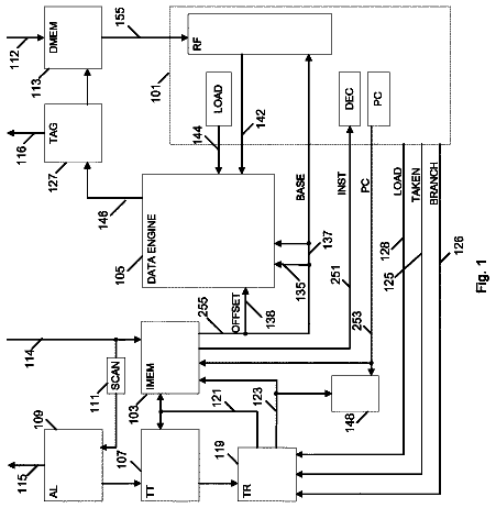
FIG. 1 is an embodiment of an exemplary block diagram of a processor core capable of executing data speculation extension (DSX) in hardware;
FIG. 2 illustrates an example of speculative instruction execution according to an embodiment;
FIG. 3 illustrates a detailed embodiment of DSX tracking hardware illustrates a detailed embodiment of DSX tracking hardware;
FIG. 4 illustrates an exemplary method of DSX mis-speculation detection performed by DSX tracking hardware;
FIGS. 5(A) -(B) illustrate an exemplary method of DSX mis-speculation detection performed by DSX tracking hardware;
FIG. 6 illustrates an embodiment of an execution of an instruction for beginning DSX;
FIG. 7 illustrates some exemplary embodiments of a YBEGIN instruction format;
FIG. 8 illustrates a detailed embodiment of an execution of an instruction such as a YBEGIN instruction;
FIG. 9 illustrates an example of pseudo-code showing the execution of an instruction such as a YBEGIN instruction;
FIG. 10 illustrates an embodiment of an execution of an instruction for beginning DSX;
FIG. 11 illustrates some exemplary embodiments of a YBEGIN WITH STRIDE instruction format;
FIG. 12 illustrates a detailed embodiment of an execution of an instruction such as a YBEGIN WITH STRIDE instruction;
FIG. 13 illustrates an embodiment of an execution of an instruction for continuing a DSX without ending it;
FIG. 14 illustrates some exemplary embodiments of a YCONTINUE instruction format;
FIG. 15 illustrates a detailed embodiment of an execution of an instruction such as a YCONTINUE instruction;
FIG. 16 illustrates an example of pseudo-code showing the execution of an instruction such as a YCONTINUE instruction;
FIG. 17 illustrates an embodiment of an execution of an instruction for aborting a DSX;
FIG. 18 illustrates some exemplary embodiments of a YABORT instruction format;
FIG. 19 illustrates a detailed embodiment of an execution of an instruction such as a YABORT instruction;
FIG. 20 illustrates an example of pseudo-code showing the execution of an instruction such as a YABORT instruction;
FIG. 21 illustrates an embodiment of an execution of an instruction for testing the status of DSX;
FIG. 22 illustrates some exemplary embodiments of a YTEST instruction format;
FIG. 23 illustrates an example of pseudo-code showing the execution of an instruction such as a YTEST instruction;
FIG. 24 illustrates an embodiment of an execution of an instruction for ending a DSX;
FIG. 25 illustrates some exemplary embodiments of a YEND instruction format;
FIG. 26 illustrates a detailed embodiment of an execution of an instruction such as a YEND instruction;
FIG. 27 illustrates an example of pseudo-code showing the execution of an instruction such as a YEND instruction;
FIGS. 28A-28B are block diagrams illustrating a generic vector friendly instruction format and instruction templates thereof according to embodiments of the invention;
FIGS. 29A-D shows a specific vector friendly instruction format 2900 that is specific in the sense that it specifies the location, size, interpretation, and order of the fields, as well as values for some of those fields.
FIG. 30 is a block diagram of a register architecture according to one embodiment of the invention;
FIGS. 31A-B is a block diagram illustrating both an exemplary in-order pipeline and an exemplary register renaming, out-of-order issue/execution pipeline according to embodiments of the invention;
FIGS. 32A-B illustrate a block diagram of a more specific exemplary in-order core architecture, which core would be one of several logic blocks (including other cores of the same type and/or different types) in a chip;
FIG. 33 is a block diagram of a processor that may have more than one core, may have an integrated memory controller, and may have integrated graphics according to embodiments of the invention;
FIG. 34 shows a block diagram of a system in accordance with an embodiment of the present invention;
FIG. 35 shows a block diagram of a first more specific exemplary system in accordance with an embodiment of the present invention;
FIG. 36 shows block diagram of a second more specific exemplary system in accordance with an embodiment of the present invention;
FIG. 37 shows a block diagram of a SoC in accordance with an embodiment of the present invention;
FIG. 38 is a block diagram contrasting the use of a software instruction converter to convert binary instructions in a source instruction set to binary instructions in a target instruction set according to embodiments of the invention.
Detailed description
In the following description, numerous specific details are set forth. However, it is understood that embodiments of the invention may be practiced without these specific details. In other instances, well-known circuits, structures and techniques have not been shown in detail in order not to obscure the understanding of this description.
References in the specification to “one embodiment,” “an embodiment,” “an example embodiment,” etc., indicate that the embodiment described may include a particular feature, structure, or characteristic, but every embodiment may not necessarily include the particular feature, structure, or characteristic. Moreover, such phrases are not necessarily referring to the same embodiment. Further, when a particular feature, structure, or characteristic is described in connection with an embodiment, it is submitted that it is within the knowledge of one skilled in the art to affect such feature, structure, or characteristic in connection with other embodiments whether or not explicitly described.
Throughout this description a technique of speculative execution referred to as data speculation extension (DSX) is detailed. Included in this description is DSX hardware and new instructions that support DSX.
DSX is similar in nature to restricted transactional memory (RTM) implementations, but simpler. For example, a DSX region does not require an implied fence. Rather, normal load/store ordering rules are maintained. Moreover, the DSX region does not set any configuration in the processor forcing atomic behavior for loads, whereas in RTM, loads and stores of a transaction are treated atomically (committed upon completion of the transaction). Additionally, loads are not buffered as they are in RTM. However, stores are buffered and committed at once when speculation is no longer needed. These stores may be buffered in dedicated speculative execution storage or in shared registers or memory locations depending upon the embodiment. In some embodiments, speculative vectorization only happens on a single thread which means there is no need to protect against interferences from other threads.
In the previously detailed vectorized loop, there would need to be dynamic checks for safety. For example, an assurance that writes to A in a given vector iteration do not overlap elements in B or C that, in the scalar loop, are read in later iterations. Embodiments below detail handling vectorization cases through the use of speculation. A speculative version indicates that each loop iteration should be executed speculatively (e.g., using instructions detailed below), and that hardware should help to perform the address checks. Instead of relying on the hardware to be solely responsible for the address checks (which requires very expensive hardware), the detailed approach uses software to provide information to assist the hardware, enabling a much cheaper hardware solution without impacting execution time or placing too much burden on the programmer or compiler.
Unfortunately, with vectorization there may be an ordering violation. Looking back at the scalar loop example detailed above:
TABLE-US-00003 for (i = 0; i < N; i++) { A[i] = B[C[i]]; }
During the first four iterations of this loop, the following memory operations will occur in the following order:
Read C[0]
Read B[C[0]]
Write A[0]
Read C[1]
Read B[C[1]]
Write A[1]
Read C[2]
Read B[C[2]]
Write A[2]
Read C[3]
Read B[C[3]]
Write A[3]
The distance (in number of operations) between accesses to the same array is three and it is also the number of speculative memory instructions in the loop once it is vectorized (made into SIMD). That distance is called a “stride.” It is also the number of memory instructions in the loop that will have address checks performed on them once the loop is vectorized. In some embodiments, this stride is conveyed to the address tracking hardware via a special instruction at the start of the loop (detailed below). In some embodiments, that instruction also clears the address tracking hardware.
Detailed herein are new instructions (DSX memory instructions) used in DSX in cases such as vectorized loop execution. Each DSX memory instruction (such as loads, stores, gathers, and scatters) includes an operand to be used during DSX that indicates a position within the DSX execution (e.g., a position in a loop being executed). In some embodiments, the operand is an immediate (e.g., an 8-bit immediate) with a numerical value of encoded order in the immediate. In other embodiments, the operand is a register or memory location storing a numerical value of encoded order.
Additionally, in some embodiments these instructions have a different opcode than their normal counterpart. These instructions may be scalar or superscalar (e.g., SIMD or MIMD). Examples of some of these instructions are found below where the mneumonic of the opcode includes an “S” (which is underlined below) to indicate that it is a speculative version and the imm8 is an immediate operand that is used to indicate a position of execution (e.g., a position in a loop being executed):
VMOV S DQA32 zmm1 {k1}{z}, mV, imm8//speculative SIMD load
VMOV S xmm1, m32, imm8/1 speculative scalar load
VSCATTER S DPS vm32z {k1}, zmm1, imm8/1 speculative scatter
Of course, other instructions may also utilize the detailed operand and opcode mneumonic (and underlying opcode) change such as logical (AND, OR, XOR, etc.) and data manipulation (add, subtract, etc.) instructions.
In a vectorized version (assuming a SIMD width of four packed data elements) of the above scalar example, the order of memory operations is:
Read C[0], C[1], C[2], C[3]
Read B[C[0]], B[C[1]], B[C[2]], B[C[3]]
Write A[0], A[1], A[2], A[3]
This order may lead to an incorrect execution if, for example, B[C[1]] overlaps with A[0]. In the original scalar order, the read of B[C[1]] happens after the write to A[0], but in the vectorized execution it happens before.
Using speculative memory instructions for the operations in the loop that might lead to incorrect execution helps deal with this problem. As will be detailed, each speculative memory instruction notifies a DSX tracking hardware (detailed below) of its position within the loop body:
TABLE-US-00004 for (i = 0; i < N; i += SIMD_WIDTH) { zmm0 = vmovsdqu32 &C[i], 0 // tells address tracker this is instruction 0 k1 = kxnor k1, k1 zmm1 = vgathersdd B, zmm0, k1, 1 // tell address tracker this is instruction 1 vmovsdqu &A[i], zmm1, 2 // tell address tracker this is instruction 2 }
The loop position information provided by each speculative memory operation can be combined with the stride to reconstruct the scalar memory operation. As speculative memory instructions execute, an identifier (id) is computed by the DSX hardware tracker for each element (id=sequence number+stride*element number within the SIMD operation). The hardware tracker uses the sequence number, the calculated id, and the address and size of each packed data element to determine if there was an ordering violation (i.e., if the element overlaps with another and was read or written out of order).
Unrolling the individual memory operations that comprise each vector memory instruction, accumulating the stride for each unrolling, and assigning the resulting numbers as “ids”, results in:
Read C[0]//id=0
Read C[1]//id=3
Read C[2]//id=6
Read C[3]//id=9
Read B[C[0]]//id=1
Read B[C[1]]//id=4
Read B[C[2]]//id=7
Read B[C[3]]//id=10
Write A[0]//id=2
Write A[1]//id=5
Write A[2]//id=8
Write A[3]//id=11
Sorting the above individual memory operations by id will reconstruct the original scalar memory ordering.
FIG. 1 is an embodiment of an exemplary block diagram of a processor core capable of executing data speculation extension (DSX) in hardware.
The processor core 106 may include a fetch unit 102 to fetch instructions for execution by the core 106 . For example, the instructions may be fetched from an L1 cache or memory. Core 106 may also include a decode unit 104 to decode the fetched instruction including those detailed below. For instance, the decode unit 104 may decode the fetched instruction into a plurality of micro-operations (micro-ops).
Additionally, the core 106 may include a schedule unit 107 . Schedule unit 107 may perform various operations associated with storing decoded instructions (e.g., received from the decode unit 104 ) until the instructions are ready for dispatch, e.g., until all source values from operands of a decoded instruction become available. In one embodiment, schedule unit 107 may schedule and/or issue (or dispatch) decoded instructions to one or more execution units 108 for execution. Execution unit 108 may include a memory execution unit, an integer execution unit, a floating-point execution unit, or other execution units. A retirement unit 110 may retire executed instructions after they are committed. In an embodiment, retirement of the executed instructions may result in processor state being committed from the execution of the instructions, physical registers used by the instructions being de-allocated, etc.
A memory order buffer (MOB) 118 may include a load buffer, a store buffer and logic to store pending memory operations that have not loaded or written back to a main memory. In some embodiments, the MOB 118 or circuitry similar to it, stores speculative stores (writes) of a DSX region. In various embodiments, a core may include a local cache, e.g., a private cache such as cache 116 that may include one or more cache lines 124 (e.g., cache lines 0 through W and that is managed by cache circuitry 139 . In an embodiment, each line of cache 116 may include a DSX read bit 126 and/or a DSX write bit 128 for each thread executing on core 106 . Bits 126 and 128 may be set or cleared to indicate (load and/or store) access to the corresponding cache line by a DSX memory access request. Note that while in the embodiment of FIG. 1 each cache line 124 is shown as having a respective bit 126 and 128 , other configurations are possible. For example, a DSX read bit 126 (or DSX write bit 128 ) may correspond to a select portion of the cache 116 , such as a cache block or other portion of the cache 116 . Also, the bits 126 and/or 128 may be stored in locations other than the cache 116 .
To aid in executing DSX operations, core 106 may include a DSX nest counter 130 to store a value corresponding to the number of DSX starts that have been encountered with no matching DSX end. Counter 130 may be implemented as any type of a storage device such as a hardware register or a variable stored in a memory (e.g., system memory or cache 116 ). Core 106 may also include a DSX nest counter circuitry 132 to update the value stored in the counter 130 . Core 106 may include a DSX check pointing circuitry 134 to check point (or store) the state of various components of the core 106 and a DSX restoration circuitry 136 to restore the state of various components of the core 106 , e.g., on abort of a given DSX, using a fallback address that either it stores or is stored in another location such as a register 140 . Additionally, core 106 may include one or more additional registers 140 that correspond to various DSX memory access requests, such as a DSX status and control register (DSXSR) to store an indication of if a DSX is active, a DSX instruction pointer (DSXXIP) (e.g., that may be an instruction pointer to an instruction at the beginning (or immediately preceding) of the corresponding DSX), and/or a DSX stack pointer (DSXSP) (e.g., that may be a stack pointer to the head of a stack that stores various states of one or more components of core 106 ). These registers may also be MSRs 150 .
DSX address tracking hardware 152 (sometimes simply called DSX tracking hardware) tracks speculative memory accesses and detects ordering violations in a DSX. In particular, this tracking hardware 152 includes an address tracker that takes in information to reconstruct and then enforce the original scalar memory order. Typically, the inputs are the number of speculative memory instructions in the loop body that need to be tracked, and some information for each of those instructions such as:
a sequence number,
the addresses the instruction accesses, and
whether the instruction incurs reads or writes to memory. If two speculative memory instructions access overlapping parts of memory, the hardware tracker 152 uses this information to determine if the original scalar order of the memory operations has been changed. If so, and if either operation is a write, the hardware triggers a mis-speculation. While FIG. 1 illustrates DSX tracking hardware 152 on its own, in some embodiments this hardware is a part of other core components.
FIG. 2 illustrates an example of speculative instruction execution according to an embodiment. At 201 , the speculative instruction is fetched. For example, a speculative memory instruction such as those detailed above is fetched. In some embodiments, this instruction includes an opcode indicating its speculative nature and an operand to indicate an ordering in a DSX. The ordering operand may be an immediate value or a register/memory location.
The fetched speculative instruction is decoded at 203 .
A determination of if the decoded speculative instruction is a part of a DSX is made at 205 . For example, is a DSX indicated in the DSX status and control register (DSXSR) detailed above? When a DSX is not active, the instruction either becomes a no operation (nop) or is executed as a normal, non-speculative instruction at 207 according to an embodiment.
When a DSX is active, the speculative instruction is speculatively executed (e.g., not committed) and the DSX tracking hardware is updated at 209 .
FIG. 3 illustrates a detailed embodiment of DSX address tracking hardware. This hardware tracks speculative memory instance. Typically, an element (e.g., SIMD element) analyzed by DSX tracking hardware is broken into portions called chunks which are no more than “B” bytes in size.
Shifting circuitry 301 shifts an address (such as a starting address) of a chunk. In most embodiments, the shifting circuitry 301 performs a right shift. Typically, the right shift is by log.sub.2B. The shifted address is subjected to a hash function performed by hash function unit circuitry 303 .
The output of the hash function is an index to a hash table 305 . As illustrated, the hash table 305 includes a plurality of buckets 307 . In some embodiments, the hash table 305 is a Bloom filter. The hash table 305 is used to detect mis-speculation, and to record the addresses, access type, sequence numbers, and id numbers of speculatively accessed data. The hash table 305 contains N “sets” with each set containing M entries 309 . Each entry 309 holds a valid bit, sequence number, id number, and access type for an element of a previously executed speculative memory instruction. In some embodiments, each entry 309 also contains a corresponding address (shown as a dashed box in the figure). Upon a DSX initiating instruction (e.g., YBEGIN and variants detailed below), all valid bits are cleared, and a “speculation active” flag is set, and on an instruction ending the DSX, the speculation active flag is cleared.
Conflict check circuitry 311 checks for a conflict per entry 309 against the element (or chunk thereof) under test 315 . In some embodiments, there is a conflict when the entry 309 is valid and at least one of: i) the access type in the entry 309 is write or ii) the access type under test is write, along with one of: i) the sequence number in the entry 309 being less than the sequence number of the element under test 315 , and the id number in the entry 309 being greater than the id number of the element under test 315 or ii) the sequence number in the entry 309 being greater than the sequence number of the element under test 315 , and the id number in the entry 309 being less than the id number of the element under test 315 .
In other words, a conflict exists when:
TABLE-US-00005 (Entry is valid) AND ((access type in entry == write) OR (access type under test == write)) AND (((Seq # in entry < Seq # under test) AND (id # in entry > id # under test)) OR ((Seq # in entry > Seq # under test) AND (id # in entry < id # under test)))
Note in most embodiments there is not a test for address overlap. This overlap is implied from hitting the entry in the hash table. A hit may occur where there is no address overlap, due to aliasing from the hash function and/or from the check being too coarse-grained (i.e., B being too large). However, there will be a hit when there is address overlap. So correctness is guaranteed, but there may be false positives (i.e., the hardware may detect mis-speculation where there is none). In an embodiment, the chunk address is stored in each entry 309 , and an additional condition for testing for mis-speculation is applied (i.e., this is logically ANDed with the above condition) where the address in entry 309 equals the address in the element under test 315 ).
An OR gate 313 (or equivalent) logically ORs the results of the conflict checks. When the result of the ORing is a 1, then a mis-speculation has likely occurred and the OR gate 313 indicates that with its output.
The total storage of this embodiment is M*N entries. That means it may track up to M*N speculatively accessed data elements. In practice, however, loops are likely to have more accesses to some of the N sets than to others. If space in any set runs out, then in some embodiments a mis-speculation is triggered to guarantee correctness. Increasing M alleviates this problem, but may force more copies of the conflict checking hardware to exist. To perform all M conflict checks simultaneously (as is done in some embodiments), there are M copies of the conflict checking logic.
Choosing the B, N, M, and hash function in a certain way, allows for the structure to be organized in a very similar manner as the L1 data cache. In particular, let B be the cache line size, N be the number of sets in the L1 data cache, M be the associativity of the L1 data cache, and let the hash function be the least significant bits of the address (after the right shift). This structure will have the same number of entries and organization as the L1 data cache, which may simplify its implementation.
Finally, note that an alternative embodiment uses separate Bloom filters for reads and writes, to avoid having to store the access type information, and to avoid having to check the access type during the conflict checks. Instead, for reads, the embodiment performs conflict checks against only the “write” filter, and if there is no mis-speculation, inserts the element into the “read” filter. Similarly, for writes, the embodiment performs conflict checks against both the “read” and “write” filters, and if there is no mis-speculation, inserts the element into the “write” filter.
FIG. 4 illustrates an exemplary method of DSX mis-speculation detection performed by DSX tracking hardware. At 401 , DSX is started or a previous speculative iteration is committed. For example, a YBEGIN instruction is executed. The execution of this instruction clears the valid bits in the entries 309 and sets a speculation active flag (if not already set) in a status register (such as the DSX status register detailed earlier). A speculative memory instruction is executed after the DSX is started and provides data elements under test.
At 403 , the data element under test from the speculative memory instruction is broken into chunks of no more than B bytes. The hash table is accessed at a granularity of B bytes (i.e., the low bits of an address are discarded). If elements are large enough and/or are not aligned, they may cross a B byte boundary and, if so, the element is broken into multiple chunks.
Per chunk, the following ( 405 - 421 ) are performed. The start address of the chunk is right shifted by log.sub.2B. The shifted address is hashed at 407 to generate an index value.
Using the index value, a look-up of a corresponding set of the hash table is made at 409 and all entries of the set are read out at 411 .
For each read out entry, a conflict check against the element under test (such as that described above) is performed at 413 . An ORing of all of the conflict checks is performed at 415 . If any check indicates a conflict at 417 (such that the OR is a 1), then an indication of mis-speculation is made at 419 . The DSX is typically aborted at this time. If there is no mis-speculation, then at 421 an invalid entry in the set is found and filled with the information for the element under test and marked valid. If no invalid entries exist, a mis-speculation is triggered.
FIGS. 5(A) -(B) illustrate an exemplary method of DSX mis-speculation detection performed by DSX tracking hardware. At 501 , DSX is started or a previous speculative iteration is committed. For example, a YBEGIN instruction is executed.
The execution of this instruction resets the tracking hardware by clearing the valid bits in the entries 309 and sets a speculation active flag (if not already set) in a status register (such as the DSX status register detailed earlier) at 503 .
At 505 , a speculative memory instruction is executed. Examples of these instructions are detailed above. A counter which is an element number under test (e) from the speculative instruction is set to zero at 507 and an id is calculated (id=sequence number+stride*e) at 509 .
A determination of if any previous write overlaps with the counter value e is made at 511 . This acts as a dependency check against previous stores (writes). For any overlapping writes, at 513 a conflict check is performed. In some embodiments, this conflict check is looking to see if: i) the sequence number in the entry 309 is less than the sequence number of the element under test 315 , and the id number in the entry 309 is greater than the id number of the element under test 315 , or ii) the sequence number in the entry 309 is greater than the sequence number of the element under test 315 , and the id number in the entry 309 is less than the id number of the element under test 315 .
If there is a conflict, then a mis-speculation is triggered at 515 . If not, or if there were not previous writes that overlapped, then a determination of if the speculative memory instruction is a write is made at 517 .
If yes, then a determination of any previous read overlaps with the counter value e is made at 519 . This acts as a dependency check against previous loads (reads). For any overlapping reads, at 521 a conflict check is performed. In some embodiments, this conflict check is looking to see if i) the sequence number in the entry 309 being less than the sequence number of the element under test 315 , and the id number in the entry 309 being greater than the id number of the element under test 315 , or ii) the sequence number in the entry 309 being greater than the sequence number of the element under test 315 , and the id number in the entry 309 being less than the id number of the element under test 315 .
If there is a conflict, then a mis-speculation is triggered at 523 . If not, or if there were not previous reads that overlapped, then the counter e is incremented at 525 .
A determination of if the counter e is equal to the number of elements in the speculative memory instruction is made at 526 . In other words, have all elements been evaluated? If no, then another id is calculated at 509 . If yes, then the hardware waits for another instruction to execute at 527 . When the next instruction is another speculative memory instruction, then the counter is reset at 507 . When the next instruction is YBEGIN, then the hardware is reset, etc. at 503 . When the next instruction is YEND, then the DSX is disabled at 529 .
YBEGIN Instruction
FIG. 6 illustrates an embodiment of an execution of an instruction for beginning DSX. As will be detailed herein, this instruction is referred to as “YBEGIN” and is used to signal the beginning of a DSX region. Of course, the instruction may be referred to by another name. In some embodiments, this execution is performed on one more hardware cores of a hardware device such as a central processing unit (CPU), graphics processing unit (GPU), accelerated processing unit (APU), digital signal processor (DSP), etc. In other embodiments, the execution of the instruction is an emulation.
At 601 , a YBEGIN instruction is received/fetched. For example, the instruction is fetched from memory into an instruction cache or fetched from an instruction cache. The fetched instruction may take one of several forms as detailed below.
FIG. 7 illustrates some exemplary embodiments of a YBEGIN instruction format. In an embodiment, the YBEGIN instruction includes an opcode (YBEGIN) and a single operand to provide a displacement for a fallback address which is where program execution should go to handle a mis-speculation as shown in 701 . In essence, the displacement value is a portion of the fallback address. In some embodiments, this displacement value is provided as an immediate operand. In other embodiments, this displacement value is stored in a register or memory location operand. Depending upon the YBEGIN implementation implicit operands for a DSX status register, a nesting count register, and/or a RTM status register are used. As detailed earlier, the DSX status register may be a dedicated register, a flag in a register not dedicated to DSX status (such as an overall status register like a flag register), etc.
In another embodiment, the YBEGIN instruction includes not only an opcode and displacement operand, but also an explicit operand for DSX status such as a DSX status register as shown in 703 . Depending upon the YBEGIN implementation implicit operands for a nesting count register and/or a RTM status register are used. As detailed earlier, the DSX status register may be a dedicated register, a flag in a register not dedicated to DSX status (such as an overall status register like a flag register), etc.
In another embodiment, the YBEGIN instruction includes not only an opcode and displacement operand, but also an explicit operand for DSX nesting count such as a DSX nest count register as shown in 705 . As detailed earlier, the DSX nest count may be a dedicated register, a flag in a register not dedicated to DSX nest count (such as an overall status register). Depending upon the YBEGIN implementation implicit operands for a DSX status register and/or a RTM status register are used. As detailed earlier, the DSX status register may be a dedicated register, a flag in a register not dedicated to DSX status (such as an overall status register like a flag register), etc.
In another embodiment, the YBEGIN instruction includes not only an opcode and displacement operand, but also explicit operands for DSX status such as a DSX status register and DSX nesting count such as a DSX nest count register as shown in 707 . As detailed earlier, the DSX status register may be a dedicated register, a flag in a register not dedicated to DSX status (such as an overall status register like a flag register, etc.), and the DSX nest count may be a dedicated register, a flag in a register not dedicated to DSX nest count (such as an overall status register. Depending upon the YBEGIN implementation an implicit operand for a RTM status register is used. As detailed earlier, the DSX status register may be a dedicated register, a flag in a register not dedicated to DSX status (such as an overall status register like a flag register), etc.
In another embodiment, the YBEGIN instruction includes not only an opcode and displacement operand, but explicit operands for DSX status such as a DSX status register, DSX nesting count such as a DSX nest count register, and RTM status as shown in 709 . As detailed earlier, the DSX status register may be a dedicated register, a flag in a register not dedicated to DSX status (such as an overall status register like a flag register, etc., and the DSX nest count may be a dedicated register, a flag in a register not dedicated to DSX nest count (such as an overall status register).
Of course other variants of YBEGIN are possible. For example, instead of providing a displacement value, the instruction includes the fallback address itself in either an immediate, register, or memory location.
Turning back to FIG. 6 , the fetched/received YBEGIN instruction is decoded at 603 . In some embodiments, the instruction is decoded by a hardware decoder such as those detailed later. In some embodiments, the instruction is decoded into micro-operations (micro-ops). For example, some CISC based machines typically use micro-operations that are derived from a macro-instruction. In other embodiments, the decoding is a part of a software routine such as a just-in-time compilation.
At 605 , any operand associated with the decoded instruction is retrieved. For example, the data from one or more of a DSX register, DSX nest count register, and/or a RTM status register are retrieved.
The decoded YBEGIN instruction is executed at 607 . In embodiments where the instruction is decoded into micro-ops, these micro-ops are executed. The execution of the decoded instruction causes the hardware to do one or more of the following acts to be performed: 1) determine that an RTM transaction is active and continue that transaction; 2) calculate a fallback address using the displacement value added to the instruction pointer of the YBEGIN instruction; 3) increment the DSX nesting count; 4) abort; 5) set DSX status to active; and/or 6) reset DSX tracking hardware.
Typically, upon an instance of an YBEGIN instruction, if there is not an active RTM transaction, then the DSX status is set to active, the DSX nest count is incremented (if the count is less than a max), the DSX tracking hardware is reset (for example, as detailed above), and a fallback address is calculated using the displacement value to start a DSX region. As detailed earlier, a status for a DSX is typically stored in an accessible location such as a register such as the DSX status and control register (DSXSR) discussed above with respect to FIG. 1 . However, other means such as a DSX status flag in a non-dedicated control/status register (such as a FLAGS register) may be utilized. Resetting of the DSX tracking hardware was also previously described. As detailed earlier, a status for a DSX is typically stored in an accessible location such as a register such as the DSX status and control register (DSXSR) discussed above with respect to FIG. 1 . However, other means such as a DSX status flag in a non-dedicated control/status register (such as a FLAGS register) may be utilized. This register may be checked by the hardware of the core to determine if a DSX was indeed taking place.
If there was some reason that the DSX cannot start, then one or more of the other potential actions takes place. For example, in some embodiments of processors that support RTM, if a RTM transaction was active then there should not have been a DSX active in the first place and the RTM is pursued. If there is something wrong with the set up of the DSX in the first place (nest count not correct), then an abort will take place. Additionally, in some embodiments, if there was no DSX then a fault is generated and no operations (a NOP) are performed. Regardless of which act is performed, in most embodiments after that act the DSX state is reset (if it was set) to indicate that there is no pending DSX.
FIG. 8 illustrates a detailed embodiment of an execution of an instruction such as a YBEGIN instruction. For example, in some embodiments this flow is box 607 of FIG. 6 . In some embodiments, this execution is performed on one more hardware cores of a hardware device such as a central processing unit (CPU), graphics processing unit (GPU), accelerated processing unit (APU), digital signal processor (DSP), etc. In other embodiments, the execution of the instruction is an emulation.
In some embodiments, for example in a processor that supports RTM transactions, a determination of if a RTM transaction is occurring is made at 801 . For example, in some embodiments of processors that support RTM, if a RTM transaction was active then there should not have been a DSX active in the first place. In this instance, something went wrong in the RTM transaction and its ending procedures should be activated. Typically, RTM transaction status is stored in a register such as a RTM control and status register. The hardware of the processor evaluates the contents of this register to determine if there is an RTM transaction occurring. When there is an RTM transaction occurring, the RTM transaction continues to process at 803 .
When there is not an RTM transaction occurring, or RTM is not supported, a determination of if a current DSX nest count is less than a maximum nest count is made at 805 . In some embodiments, a nest count register to store the current nest count is provided by the YBEGIN instruction as an operand. Alternatively, a dedicated nest count register may exist in hardware to be used to store the current nest count. The maximum nest count is the maximum number of DSX starts (e.g., via a YBEGIN instruction) that can occur without a corresponding DSX end (e.g., via a YEND instruction).
When the current DSX nest count is greater than the maximum, an abort occurs at 807 . In some embodiments, an abort triggers a rollback using restoration circuitry such as DSX restoration circuitry 135 . In other embodiments, a YABORT instruction is executed as detailed below which not only performs a rollback to the fallback address, but also discards speculatively stored writes and resets the current nest count and sets the DSX status to inactive. As detailed above, DSX status is typically stored in a control register such as a DSX status and control register (DSXSR) shown in FIG. 1 . However, other means such as a DSX status flag in a non-dedicated control/status register (such as a FLAGS register) may be utilized.
When the current nest count is not greater than the maximum, the current DSX nest count is incremented at 809 .
The description continues in the full USPTO document.
 Lapsed, fee not paid4 drawings