Technical field
The present disclosure relates generally to touch screens and relates more specifically to the filtering of touch points through virtual areas defined on a touch screen.
Background
Touch screens are present in many different types of common modern electronic devices, such as cellular telephones, tablet computers, portable music and video devices, personal digital assistants, portable gaming devices, and so on. In these electronic devices the touch screen is part of the user interface of the device. The touch screen typically includes a display, touch sensors, and a touch controller. The touch sensors are typically some sort of transparent sensor array, such as an ultrasonic, resistive, vibration, or capacitive sensor array, that is attached to or formed as an integral part of the display. When a user touches the sensor array either with a finger or a stylus, for example, the sensor array generates corresponding electronic sensor signals that are provided to the touch controller. From these sensor signals, the touch controller determines the type of “touch event” along with various characteristics of the touch event, and provides this information to processing circuitry in the electronic device. The processing circuitry operates in response to this information to allow a user to control the electronic device or an application running on the processing circuitry through these touches of the touch screen.
The touch controller typically captures frame data from the touch sensors and processes this frame data to determine the type of touch event that has occurred on the touch screen. This processing is typically referred to as touch frame processing and through this processing the touch controller determines the type of touch event and the location of the touch event on the touch screen. The touch controller must detect and report (to the processing circuitry) different types of touch events, such as when a user initially touches the touch screen, when the user has stopped touching the touch screen, and when a touch is moving on the touch screen, and when a moving touch has stopped moving.
Common touch screen device includes a touch sensor, a touch controller and a display. The touch sensor is a user interface device integrated with a panel which, when touch with a finger or stylus, produces signals from which the controller can determine touch event and its touch properties (position, size, pressure etc). The transparent sensor is usually mounted onto the display so that the output can be directly seen by the user together with the device's graphical user interface, thus allowing direct interaction. For example, the user can select a button object on the display screen by directly touching the button on the display. The device application program can determine which object was touched using the information generated by the sensor and reported by the controller. Many hand-held devices such as smart phones, personal digital assistants (PDAs), media players, tablet computers and similar devices include touch screens. As more and more interactive and advanced user applications are developed for these devices, more and more information has to be generated and decoded by the touch controller.
Touch controllers also typically provide high-level functionality, such as gesture recognition, descriptive touch data, shape recognition, the definition of multiple touch areas on the touch screen, single touch or multiple touch detection, and so on. Such high-level functionality requires a lot of information be transferred between the touch controller and the touch sensor and between the touch controller and the processing circuitry. While it is desirable to provide such high-level functionality for applications running on the processing circuitry that utilize such high-level functions, not all applications utilize all or in some cases any of these high-level functions.
There is a need for improved filtering of touches in order to eliminate or lower the unnecessary transfer of information relating to high-level functionality for applications that do not utilize such high-level functions.
Summary
According to one embodiment, a touch controller includes a touch frame processing component adapted to receive sensor signals containing information about a touch point on a touch screen. The touch frame processing component processes the sensor signals to generate touch information associated with each touch point. A touch coordinate processing component is coupled to receive touch information from the touch frame processing component and includes virtual area parameters that define a plurality of virtual areas on the touch screen. The touch coordinate processing component is operable to identify which one of the plurality of virtual areas contains the current touch point and to report or filter the current touch point as a function of the identified virtual area.
According to another embodiment, a method of filtering detected touch points on a touch screen includes determining a location of a touch point on a touch screen, identifying which one of a plurality of virtual areas on the touch screen includes the location the touch point, and filtering reporting of the touch point based upon the identified virtual area.
Brief description of the drawings
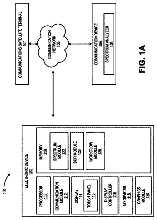
FIG. 1A is a functional block diagram of an electronic device including a touch controller operable to execute a virtual area filtering algorithm according to one embodiment.
FIG. 1B is a diagram graphically illustrating the content of the touch information generated by the touch controller of FIG. 1A .
FIGS. 2A-2C are diagrams illustrating touch-in, touch-motion, and touch-out types of touch events, respectively.
FIG. 3 is a functional block diagram of the touch controller of FIG. 1A according to one embodiment.
FIG. 4 is a top view of the touch screen of FIG. 1A illustrating location-based filtering of touch points through the definition of virtual areas on the touch screen.
FIG. 5 is a top view of the touch screen of FIG. 1A illustrating another example of location-based filtering of touch points through the definition of virtual areas on the touch screen.
FIG. 6 is a top view of the touch screen of FIG. 1A illustrating layer-based filtering of touch points through the definition of virtual areas on the touch screen.
FIG. 7 is a top view of the touch screen of FIG. 1A illustrating touch-count-based filtering of touch points through the definition of virtual areas on the touch screen.
FIG. 8 is a top view of the touch screen of FIG. 1A illustrating other virtual-area-parameters-based filtering of touch points through the definition of virtual areas on the touch screen.
FIG. 9 is a diagram illustrating the configurable parameters of the virtual areas discussed with reference to FIGS. 4-8 .
FIG. 10 is a flowchart illustrating a process executed by the virtual area filtering algorithm of FIG. 1 according to one embodiment.
FIG. 11 is a flowchart illustrating in more detail the operation of identifying the virtual area containing a current touch point of FIG. 10 .
FIG. 12 is a flowchart illustrating in more detail the operation of checking the top layer virtual areas of FIG. 11 .
FIG. 13 is a flowchart illustrating in more detail the operation of checking the bottom layer virtual areas of FIG. 11 .
FIGS. 14A-14C are a flowchart illustrating in more detail the operation of applying touch count filtering of FIG. 10 .
FIG. 15 is a flowchart illustrating in more detail the operation of filtering touch points based upon other virtual area parameters of FIG. 10 .
Detailed description
FIG. 1A is a functional block diagram of an electronic device 100 including a touch controller 102 that executes a virtual area filtering algorithm 103 according to one embodiment. In operation, the touch controller 102 detects touches or touch points P(X,Y) on a touch screen 104 and associates touch information TI with each detected touch point. The touch controller 102 thereafter executes the virtual area filtering algorithm 103 to detect which virtual area VA defined on the touch screen 104 contains the touch point P(X,Y) and to determine whether to report the touch information TI or filter the touch information (i.e., block reporting of the touch information) to processing circuitry 108 ), as will be described in more detail below. In this way the touch controller 102 reports only touch information TI for touch points P(X,Y) that the virtual area filtering algorithm 103 determines should be reported to the processing circuitry 108 . The touch information TI that the virtual area filtering algorithm 103 generates includes identification information for the appropriate virtual area VA containing the touch point P(X,Y), allowing applications or “apps” 110 running on the processing circuitry 110 that rely on such high-level identification information to take desired actions based on this information, as will also be described in more detail below.
In the following description, certain details are set forth in conjunction with the described embodiments to provide a sufficient understanding of the present disclosure. One skilled in the art will appreciate, however, that the other embodiments may be practiced without these particular details. Furthermore, one skilled in the art will appreciate that the example embodiments described below do not limit the scope of the present disclosure, and will also understand that various modifications, equivalents, and combinations of the disclosed embodiments and components of such embodiments are within the scope of the present disclosure. Embodiments including fewer than all the components of any of the respective described embodiments may also be within the scope of the present disclosure although not expressly described in detail below. Finally, the operation of well-known components and/or processes has not been shown or described in detail below to avoid unnecessarily obscuring the present disclosure.
The touch screen 104 includes a number of touch sensors 112 positioned on the touch screen to detect touch points P(X,Y), with three touch sensors being shown in the embodiment of FIG. 1A . Each touch sensor 112 generates a corresponding sensor signal responsive to a touch point P(X,Y) and provides this signal to the touch controller 102 for processing. The touch sensors 112 are typically contained in some sort of transparent sensor array that is part of the touch screen 104 . The number and location of the sensors 112 can vary as can the particular type of sensor, such as ultrasonic, resistive, vibration, or capacitive sensors, as will be appreciated by those skilled in the art. Three sensors 112 positioned as shown are illustrated merely by way of example.
A user touching the touch screen 104 with his or her finger, stylus, or other suitable device corresponds to a touch point P(X,Y). In response to a touch point P(X,Y), the sensors 112 generate respective signals that are provided to the touch controller 102 which, in turn, processes these signals to generate touch information TI for the corresponding touch point. The touch information TI that the touch controller 102 generates for each touch point P(X,Y) includes location information and touch-event (TE) information for the touch point, and typically includes other information as well such as the size of the touch point, the pressure of the touch point, a touch-point identifier TIDn, and so on, as will be appreciated by those skilled in the art. This is illustrated graphically in the diagram of FIG. 1B . The location information is an X coordinate and a Y coordinate that together define the location of the touch point P(X,Y) on the surface of the touch screen 104 . An X-axis and Y-axis are shown in FIG. 1A , with the X coordinate corresponding to a point along the X-axis and the Y coordinate to a point along the Y-axis. Thus, a touch point P(X.sub.1,Y.sub.1) corresponds to a touch point on screen 104 at location X.sub.1 on the X-axis and Y.sub.1 on the Y-axis. The touch controller 102 scans the sensor signals of the sensors 112 and processes these signals to generate the touch information TI. The sensed or detected values of the sensor signals from all sensors 112 at a given point in time (i.e. for a given scan) is termed “frame data.” Accordingly, the touch controller 102 processes frame data from one or more frames to determine touch information TI for each touch point P(X,Y), as will be described in more detail below with reference to FIGS. 2A-2C .
As previously mentioned, the touch information TI that the touch controller 102 generates also includes touch-event TE information. This touch-event TE information associates one of three types of touch events with each touch point P(X,Y): 1) touch-in event; 2) touch-motion event; and 3) touch-out event. The detection of a touch-in event is illustrated in FIG. 2A and is the initial occurrence of a touch point P(X,Y). A touch-in event may be defined as moving downward on an area of the touch screen 104 over a period of time tep. So the touch controller 102 determines a touch-in event has occurred if an initial touch point P(X,Y) is detected and the point is determined to be moving downward on an area on the touch screen 104 over the time tep. For example, where the touch screen 104 is a capacitive touch screen, a touch-in event may be defined as a decreasing capacitance value with respect to a “no-touch” reference capacitance value or as a decreasing voltage over the time tep. As seen in the example of FIG. 2A , the touch controller 102 detects an initial touch-point P(X,Y) at a time t 0 and determines that this touch point appears to be a touch-in event. The touch controller 102 subsequently monitors parameters associated with this initial touch point P(X,Y) and determines whether the touch point is moving downward on an area of the touch screen 104 over the time tep. During this time period between times t 0 and tep the touch controller 102 monitors frame data from the sensor signals from sensors 112 . At the time tep after the initial time t 0 the touch controller 102 determines the touch point P(X,Y) corresponds to a touch-in event and associates a touch-in event with this touch point.
FIG. 2B illustrates the detection of a touch-motion event by the touch controller 102 . The touch controller 102 determines a touch-motion event has occurred if a succeeding touch point is associated with a previous touch point P(X,Y) or touch-in event. Assume, for example, an initial touch point P.sub.1(X,Y) has been detected at a time t 0 as seen in FIG. 2B and that this initial touch point is a touch-in event. Now assume a succeeding or subsequent touch point P.sub.2(X,Y) is detected at a time t 1 . Because a prior touch-in event or prior touch point P.sub.1 (X,Y) exists, the touch controller 102 associates a touch-motion event with this subsequent touch point P.sub.2(X,Y). A touch-motion event indicates movement across the touch screen 104 , such as when a user is sliding his or her finger across the touch screen to perform a desired action. Thus, when a previous touch point P.sub.1(X,Y) exists, either in the form of a touch point that is a touch-in event or a prior touch-motion event, and the touch controller 102 detects a subsequent touch point P.sub.2(X,Y), then the touch controller associates a touch-motion event with this subsequent touch point.
FIG. 2C illustrates the detection of a touch-out event by the touch controller 102 . A touch-out event may be defined as moving upward on an area of the touch screen 104 over a period of time tip. The touch controller 102 determines a touch-out event has occurred if “no touch” is detected for a touch point P(X,Y) and the point is determined to be moving upward on an area on the touch screen 104 over the time tip. Where the touch screen 104 is a capacitive touch screen, a touch-out event may be defined as an increasing capacitance value or returning to the no-touch reference capacitance value, or as an increasing voltage over the time tip. FIG. 2C illustrates the touch controller 102 detects a touch-point P(X,Y) at a time t 0 and determines that this touch point appears to be a touch-out event (e.g., the associated capacitance or voltage has increased above a threshold value). The touch controller 102 subsequently monitors parameters associated with this touch point P(X,Y) and determines the touch point is moving upward on an area of the touch screen 104 over the time tlp. Thus, at the time tip after the initial time t 0 the touch controller 102 determines the touch point P(X,Y) corresponds to a touch-out event and associates a touch-out event with this touch point.
FIG. 3 is a functional block diagram of the touch controller 102 of FIG. 1A according to one embodiment. In the embodiment of FIG. 3 touch controller 102 includes a touch frame processing component 300 that receives frame data that includes sensor signals from the touch sensors 112 ( FIG. 1A ). As previously discussed, the sensor signals from the touch sensors 112 contain information about touch points P(X,Y) on the touch screen 104 ( FIG. 1A ). The touch frame processing component 300 processes the frame data including the sensor signals to generate touch information TI for detected touch points P(X,Y) on the touch screen 104 . As previously described, this touch information TI includes the actual detection itself of a given touch point P(X,Y) along with determination of location information in the form of X and Y coordinates along with event type information for the touch point (i.e., whether a touch-in, touch-motion, or touch-out event is associated with the touch point). The determined touch information for a given touch point P(X,Y) is assigned a touch-event identifier TIDn and this touch-event identifier along with the corresponding location, event type, and other information are output by the touch frame processing component 300 .
A touch coordinate processing component 302 receives touch information TI from the touch frame processing component 300 and executes the virtual area filtering algorithm 103 to detect which virtual area VA defined on the touch screen 104 contains the touch point P(X,Y) and to determine whether to report or filter the touch information TI from the application 110 executing on processing circuitry 108 in the electronic device 100 of FIG. 1A . Virtual area (VA) registers 306 store a plurality of configurable parameters that define and characterize each virtual area VA, as will be described in more detail below with reference to FIG. 9 . When the virtual area filtering algorithm 103 determines the touch information TI should be reported to the application 110 , the touch information TI for the current touch point P(X,Y) along with high-level functionality information associated with the defined virtual areas VA are provided to a first-in-first-out (FIFO) buffer 304 . The touch information TI along the high-level functionality information are collectively referred to as advanced touch information ATI. The FIFO buffer 304 includes a software driver 304 a and hardware buffer 304 b as shown in FIG. 3 . The FIFO buffer 304 stores the advanced touch information ATI for a number of touch points P(X,Y) being reported and subsequently provides the stored advanced touch information to the application 110 ( FIG. 1A ) on a first-in-first-out basis. In this way, when the virtual area filtering algorithm 103 stores the advanced touch information ATI of a detected touch point P(X,Y) in the FIFO buffer 304 the algorithm is said to have “reported” the advanced touch information to the application 110 . Conversely, when the virtual area filtering algorithm 103 determines the advanced touch information ATI should not be reported to the application 110 , the algorithm does not report or “filters” reporting of this advanced touch information by not providing the advanced touch information to the FIFO buffer 304 . Note in the present description, for the sake of brevity the filtering of a touch point P(X,Y) and reporting of the advanced touch information ATI for a touch point may be simply referred to as filtering or reporting of the touch point.
In operation, when the touch frame processing component 300 detects the presence of a touch point P (X, Y), the component determines the type of touch event TE associated with the detected touch point and provides the corresponding touch information TI to the touch coordinate processing component 302 . From this touch information TI, the virtual area filtering algorithm 103 determines the virtual area VA location of the detected touch point P(X,Y) and thereafter processes the received touch information to generate high-level touch information related to the defined virtual areas VA, and to determine whether to report or filter the touch point. The virtual area filtering algorithm 103 in this way enables the touch controller 102 to filter the reporting of touch information TI for touch points P(X,Y) based upon the definition of virtual areas VA on the touch screen 104 . Where such high-level functionality of filtering based on virtual areas VA is not needed by the applications 110 , the virtual area filtering algorithm 103 can configured accordingly, thereby preventing the unnecessary transfer of advanced touch information between the touch controller and the processing circuitry 108 when such high-level functionality is not needed.
Before describing the operation of the virtual area filtering algorithm 103 in more detail, several sample virtual area VA definitions will first be discussed with reference to FIGS. 4-8 , FIG. 4 is top view of the touch screen 104 of FIG. 1A illustrating location-based touch point filtering based upon valid and invalid virtual areas VA defined on the touch screen. In the example of FIG. 4 two virtual areas VA 1 and VA 2 are defined. The first virtual area VA 1 and second virtual area VA 2 are defined along the left and right bottom portions of the touch screen 104 , respectively. A first touch point P 1 (X 1 ,Y 1 ) is located in the first virtual area VA 1 and a second touch point P 2 (X 2 , Y 2 ) located in the second virtual area VA 2 . The remainder of the touch screen 104 , namely the portion 400 of the touch screen not contained in virtual area Va 1 or VA 2 , is as an undefined or invalid virtual area VA of the touch screen.
In FIG. 4 , the touch controller 102 filters touch points P(X,Y) as a function of the location of the touch point and the defined virtual areas VA 1 and VA 2 . More specifically, if a touch point P(X,Y) is contained within or located in one of the defined virtual areas VA 1 and VA 2 then the virtual area filtering algorithm 103 reports the touch information TI for such a touch point along the virtual area VA containing that touch point for use by the applications 110 . Thus, the touch information TI reported by the virtual area filtering algorithm 103 to the applications 110 includes a virtual area identification VAID identifying the virtual area VA containing the touch point P(X,Y). There is a maximum number N of virtual areas VA that can be defined on the touch screen 104 , and each virtual area is assigned a corresponding virtual area identification VAID 1 -VAIDN. So in the example of FIG. 4 , the touch information TI for the touch points P 1 (X 1 ,Y 1 ) and P 2 (X 2 ,Y 2 ) would be reported to the applications 110 running on the processing circuitry 108 of FIG. 1A , including identifications VAID 1 for touch point P 1 (X 1 ,Y 1 ) and VAID 2 for touch point P 2 (X 2 ,Y 2 ). Conversely, the touch points P 3 (X 3 ,Y 3 ) and P 4 (X 4 ,Y 4 ) located in the invalid portion 400 of the touch screen 104 are filtered and accordingly not reported to applications 110 .
FIG. 5 is a top view of the touch screen 104 of FIG. 1A illustrating another example of location-based filtering of touch points through the definition of multiple virtual areas VA 1 -VA 4 on the touch screen. The example of FIG. 5 illustrates that the virtual areas VA can take on different shapes, with the virtual areas VA 1 , VA 2 , and VA 3 being circular and the virtual area VA 4 being the remaining area of the touch screen 104 not contained in the virtual areas VA 1 , VA 2 , and VA 3 . The virtual areas VA can have any shape that can be suitably defined, such as square, rectangular, circular, elliptical, and so on. This example includes three virtual areas VA 1 , VA 2 , and VA 4 that are “enabled” and one virtual area VA 3 that is “disabled.” Each virtual area VA as an enablement parameter that may be set for that area, where the enablement parameter is either enabled such that touch points P(X,Y) occurring in the virtual area will be reported (ignoring other filtering criteria that may result in filtering) or disabled such the touch points occurring in the virtual area will not be reported. In this example, the virtual area filtering algorithm 103 reports touch point P 1 (X 1 ,Y 1 ) located in virtual area VA 1 , touch point P 2 (X 2 ,Y 2 ) located in virtual area VA 2 , and touch points P 4 (X 4 ,Y 4 ) and P 5 (X 5 ,Y 5 ) contained in virtual area VA 4 . The virtual area VA 3 is a disabled virtual area so the touch point P(X 3 ,Y 3 ) located in this area is filtered and thus not reported to the applications 110 . The virtual area filtering algorithm 103 reports the advanced touch information ATI including the corresponding virtual area identification VAID for the touch points P 1 (X 1 ,Y 1 ), P 2 (X 2 ,Y 2 ), P 4 (X 4 ,Y 4 ) and P 5 (X 5 ,Y 5 ). For the touch point P 1 (X 1 ,Y 1 ) this advanced touch information ATI includes the virtual area identification VAID 1 , for the touch point P 2 (X 2 ,Y 2 ) the touch information includes identification VAID 2 , while for touch points P 4 (X 4 ,Y 4 ) and P 5 (X 5 ,Y 5 ) the touch information includes identification VAID 4 .
FIG. 6 is a top view of the touch screen 104 of FIG. 1A illustrating layer-based filtering of touch points P(X,Y) through the definition of virtual areas on the touch screen. In the example of FIG. 6 , two virtual areas VA 1 and VA 2 are defined as shown, each of these virtual areas being a square area. This example illustrates the use of another property that can be defined for a virtual area VA. More specifically, in addition to the parameters defining the shape of the virtual area VA a number of other parameters are defined for each virtual area. These parameters define various characteristics of the virtual area VA. Each of the virtual areas VA 1 and VA 2 in FIG. 6 has a layer parameter of the virtual area defined. The layer parameter of each virtual area VA can be defined as either a top-layer or a bottom-layer.
The use of the layer parameter enables overlapping virtual areas VA to be utilized in defining various desired overall virtual area shapes. For example, in the example of FIG. 6 the use of the two virtual areas VA 1 and VA 2 can be utilized to define the outer shaded area for “grip suppression” for example. Some applications 110 ignore touches along the outer periphery of the touch screen 104 , namely in the outer shaded area in FIG. 6 . This is true because a user, when we merely holding the electronic device 100 containing the touch screen 104 , may apply touch points P(X, Y) such as touch points P 1 (X 1 ,Y 1 ) and P 2 (X 2 ,Y 2 ) in this outer periphery area of the screen 104 .
To detect and filter touch points P(X,Y) such as touch points P 1 (X 1 ,Y 1 ) and P 2 (X 2 ,Y 2 ) in the shaded outer periphery region in FIG. 6 , the first virtual area VA 1 is defined as a bottom layer and the second virtual area VA 2 is defined as a top layer. In addition, the virtual area VA 1 is a disabled while the virtual area VA 2 is enabled. As a result, the virtual area filtering algorithm 103 reports the touch points P 3 (X 3 ,Y 3 ) and P 4 (X 4 ,Y 4 ) located in virtual area VA 2 while the touch points P 1 (X 1 ,Y 1 ) and P 2 (X 2 ,Y 2 ) located in virtual area VA 1 are filtered and thus not reported to the applications and 110 running on the processing circuitry 108 . This configuration of the virtual areas VA 1 and VA 2 results in “grip suppression” in that touch points P(X,Y) in the shaded peripheral region are filtered while touch points in virtual area VA 2 on the interior of the touch screen 104 are reported.
Through the use of the layer parameter only to virtual areas VA, namely virtual areas VA 1 and VA 2 , are required for the grip suppression configuration just described. Without the layer parameter such functionality could still be performed but it would require the definition of more virtual layers VA. For example, without the layer parameter the same functionality could be performed through the interior virtual area VA 2 in combination with four other virtual areas defined around the periphery of the touch screen 104 . Thus, five virtual areas VA are required without the use of a layer parameter whereas only the two virtual areas VA 1 and VA 2 are required with the use of the layer parameter. The layer parameter accordingly simplifies the configuration of virtual areas VA for grip suppression or edge filtering, as will be appreciated by those skilled in the art.
FIG. 7 is a top view of the touch screen 104 of FIG. 1A illustrating touch-count-based filtering of touch points P(X,Y) through the virtual areas VA on the touch screen. A virtual-area-touch-count (VATC) threshold is another parameter that may be defined for each virtual area VA and defines a maximum number of touch points P(X, Y) that will be reported for the particular virtual area. When the VATC threshold of the virtual area VA is set, once a touch count TC indicates the number of touch points P(X,Y) detected in the virtual area has reached the VATC threshold, future touch points in the virtual area are filtered. In the example of FIG. 7 , the virtual area VA 1 has its VATC threshold equal to 1 such that only one touch point P(X,Y) for this virtual area is reported and all succeeding touch points are filtered, The virtual area VA 2 has its VATC threshold set to 2 such that two touch points P(X,Y) detected in this virtual area will be reported while all succeeding touch points will be filtered. Similarly, the virtual areas VA 3 and VA 4 have their VATC thresholds set equal to 3 and 4, respectively, such that three and four touch points P(X,Y) will be reported for these areas with subsequent touch points then being filtered.
FIG. 8 is a top view of the touch screen 104 of FIG. 1A illustrating other virtual-area-parameters-based filtering of touch points P(X,Y) through the definition of additional various parameters for the virtual areas VA on the touch screen. Referring back to FIG. 1B , recalled the touch information TI associated with each touch point P(X,Y) includes touch event TE type information, size or area information (i.e., whether the touch point corresponds to a stylus, finger, palm, large area, etc.), pressure or weight, and direction or orientation information. The virtual areas VA defined on the touch screen 104 can accordingly include corresponding parameters that allow filtering of touch points P(X,Y) based on the various information contained in the touch information TI associated with each touch point.
FIG. 8 illustrates filtering of touch points P(X, Y) through the definition of various parameters for the virtual areas VA where these parameters correspond to information contained in the touch information TI associated with the touch point. In the example of FIG. 8 , the enablement parameter of the virtual area VA 1 is disabled meaning that any touch points P(X,Y) detected in this virtual area will be filtered. For the virtual area VA 2 a touch-size parameter is set to “stylus” such that only touch points P(X,Y) indicated as corresponding to a stylus touch will be reported. Thus, when the touch information TI for a touch point P(X,Y) indicates the touch point corresponds to a finger or palm touch, the touch point will be filtered if it is detected in the virtual area VA 2 .
A third virtual area VA 3 is configured such that only “moving” touch points P(X,Y) detected in this virtual area will be reported and all other types of touch points will be filtered. Thus, when the touch event TE of a touch point P(X,Y) detected in the virtual area VA 3 has the type touch-motion then the virtual area filtering algorithm 103 will report this touch point. If a touch point P(X,Y) detected in the virtual area VA 3 has touch event TE type touch-in or touch-out then this touch point will be filtered. In the example FIG. 8 , a fourth virtual area VA 4 is configured such that only touch-in and touch-out type touch events TE will be reported, and any touch-motion type touch events will be filtered. Thus, the virtual area VA 4 is functionally the complement of the virtual area VA 3 .
Finally, in the example of FIG. 8 the virtual areas VA 5 , VA 6 , and VA 7 are configured to filter touch points P(X,Y) where the corresponding touch information TI indicates the size of the touch point is a large area touch point and according to defined touch-count criteria indicated by the corresponding circles in each of these virtual areas in FIG. 8 . Thus, virtual area VA 5 filters any touch point P(X,Y) having a large area size and limits the number of non-large area touch points to three (i.e., three non-large area touch points detected in the virtual area VA 5 are reported and then succeeding non-large area touch points filtered). Similarly, the virtual area VA 6 filters any touch point P(X,Y) having a large area size and limits the number of non-large area touch points to two (i.e., two non-large area touch points detected in the virtual area VA 6 are reported and then succeeding non-large area touch points filtered). The virtual area VA 7 filters any touch point P(X,Y) having a large area size and limits the number of non-large area touch points to one (i.e., one non-large area touch point detected in the virtual area VA 7 is reported and then succeeding non-large area touch points filtered).
FIG. 9 is a diagram illustrating the configurable parameters of the virtual areas VA discussed with reference to FIGS. 4-8 . These configurable parameters are stored in the VA registers 306 of FIG. 3 and include parameters corresponding to information contained in the touch information TI generated for a touch point P(X,Y) as well as other configurable parameters to allow for comprehensive high-level filtering of touch points based upon the defined virtual areas VA. The touch count (TC), touch size, and touch event TE parameters each correspond directly to information contained in the touch information TI generated for touch point P(X,Y) and allow filtering on these bases. The touch count TC is an integer value defining the maximum number of touch points P(X,Y) that may be reported for the virtual area VA. A touch size parameter TSP is set to a value corresponding to one the permissible sizes of the touch point, such as stylus, finger, palm, large area, and so on depending on the specific size information generated as part of the touch information TI. The virtual area touch event TE parameters are set, for filtering purposes, to one or more of the types of touch events that may be associated with the touch point P(X,Y), namely touch-in, touch-out, and touch-motion type of event. This type of filtering was previously described with reference to FIG. 8 and virtual areas VA 3 and VA 4 , where virtual area VA 3 is configured such that only “moving” touch points P(X,Y) (i.e., touch event TE is of the type touch-motion) that are detected in this virtual area will be reported and all other types of touch points will be filtered. So in this situation, the VA touch event TE parameters of virtual area VA 3 are set to “touch-motion” such that touch-motion events in this virtual area reported. Recall, the virtual area VA 4 of FIG. 8 is configured such that only touch-in and touch-out type touch events TE will be reported, and any touch-motion type touch events will be filtered. In this situation, the VA touch event TE parameters for virtual area VA 4 are set to touch-in and touch-out.
The virtual area identification VAID parameter is a numeric value assigned to each virtual area VA to identify that area. The VAID parameter has an integer value from 1 to N where N is the maximum number of virtual areas that may be defined on the touch screen 104 ( FIG. 1 ). So each defined virtual area VA is assigned one of the N values. When a given touch point P(X,Y) is found not to be located in any of the defined virtual areas VA, the VAID parameter associated with that touch point is set to an INVALID state or value (i.e., a value indicating that the touch point is not located in a valid or defined virtual area VA), as will be explained in more detail below with reference to FIG. 10 . The layer parameter defines a virtual area VA as either a top layer or bottom layer and allows overlapping areas to be utilized in forming desired overall virtual areas on the touch screen 104 , as discussed above with regard to FIG. 6 . Each virtual area VA may also be enabled or disabled through the enablement parameter, where a touch point P(X,Y) located in the given area is not reported when this parameter is set to disabled and is reported, subject to the other parameters for the virtual area, when the enablement parameter is enabled.
The shape of each virtual area VA is also defined through VA coordinate parameters. The number and definitions of the VA coordinate parameters will vary depending on the number of shapes for the virtual areas VA that are supported by the touch controller 102 . For example, if the virtual area VA is a rectangular area as in FIG. 7 then the VA coordinates defining the virtual area are a start point P.sub.S(X.sub.S,Y.sub.S) and an end point P.sub.E(X.sub.E,Y.sub.E). If the virtual area VA is instead a circular area, the VA coordinates defining this type of virtual area would be a center point P.sub.CIR(X.sub.CIR,Y.sub.CIR) and a radius R. Virtual areas VA having other shapes may be defined through the use of suitable additional VA coordinates that allow for definition of the desired virtual area shapes.
FIG. 10 is a flowchart illustrating a process corresponding to the virtual area filtering algorithm 103 of FIG. 1 according to one embodiment. The process starts in step 1000 and proceeds immediately to step 1002 and receives touch information TI for a current touch point P.sub.C(X,Y) to be processed by the virtual area filtering algorithm 103 . From step 1002 the process proceeds to step 1004 and checks each virtual area VA defined for the touch screen 104 to identify the location of the current touch point P.sub.C(X,Y) being processed by the virtual area filtering algorithm 103 . Identifying the location of the current touch point P.sub.C(X,Y) in this context means identification of the virtual area VA containing the current touch point P.sub.C(X,Y). The same is true for “identifying the location of the previous touch point P.sub.P(X,Y)” discussed below with reference to other figures.
Once the process has identified the virtual area VA containing the current touch point P.sub.C(X,Y), the process proceeds to step 1006 and assigns virtual area identifier VAID of the identified virtual area to the current touch point. For example, if the current touch point P.sub.C(X,Y) corresponds to the touch point P 1 (X 1 ,Y 1 ) in FIG. 5 , then in step 1006 the process assigns the virtual area identifier VAID=1 because in this situation the touch point is located in the virtual area VA 1 .
The description continues in the full USPTO document.
 Lapsed, fee not paid17 drawings