 Lapsed, fee not paid8 drawings
Software & Apps · US 9,785,018 B2
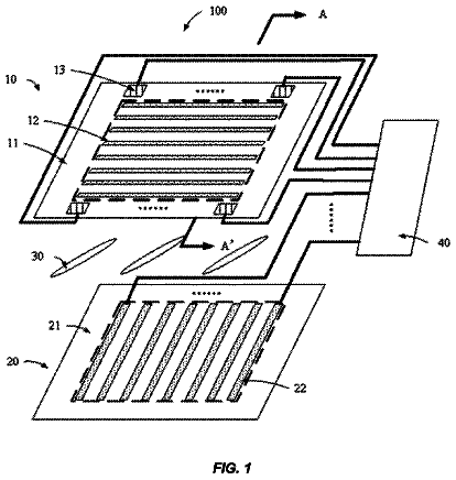
Touch liquid crystal display and method of controlling the same
A touch liquid crystal display is disclosed.
US 9,785,244 B2 · Assignee: RICOH COMPANY, LTD. · Inventors: Sato; Tomotoshi et al.
Sheet 1 of 17 from the published document. All sheets in the USPTO PDF
An image projection apparatus includes a projection unit configured to project an image onto a projection target; a recognition unit configured to recognize an instruction action for the image being projected by the projection unit; a storage control unit configured to store correspondence information in which multiple instruction actions are associated with image output controls, respectively, for each type of image in a storage device; a determination unit configured to determine, on the basis of the type of the image being projected by the projection unit, correspondence information for image output control; and a projection control unit configured to perform, on the basis of the correspondence information determined by the determination unit and the instruction action recognized by the recognition unit, image projection control corresponding to the image output control that is associated with the instruction action.
There is a known conventional technology where an image that is projected onto a projection target (e.g. a wall) by an image projection apparatus, such as a projector, is directly touched, as an instruction action, as if the image were a touch panel being touched or some instruction action (action, such as moving a hand) is made against the projected image so that a command (output control) that is allocated to the instruction action is executed (see, for example, Japanese Patent Application Laid-open No. 2003-233452). Recent image projection apparatuses can project video images in addition to still images and thus there are few common instruction actions for still and video images. For this reason, users have to remember instruction actions according to the image types and, furthermore, because the accuracy with which instruction actions are recognized is limited, misrecognition rates i
1 of 17 drawing sheets so far from the published document, cropped to the drawing. Every sheet is in the USPTO PDF.
What the patent claimed, word for word. All of it is now free to use.
The present application claims priority to and incorporates by reference the entire contents of Japanese Patent Application No. 2013-043393 filed in Japan on Mar. 5, 2013 and Japanese Patent Application No. 2013-260604 filed in Japan on Dec. 17, 2013.
The present invention relates to an image projection apparatus, a system, and an image projection method.
There is a known conventional technology where an image that is projected onto a projection target (e.g. a wall) by an image projection apparatus, such as a projector, is directly touched, as an instruction action, as if the image were a touch panel being touched or some instruction action (action, such as moving a hand) is made against the projected image so that a command (output control) that is allocated to the instruction action is executed (see, for example, Japanese Patent Application Laid-open No. 2003-233452).
Recent image projection apparatuses can project video images in addition to still images and thus there are few common instruction actions for still and video images. For this reason, users have to remember instruction actions according to the image types and, furthermore, because the accuracy with which instruction actions are recognized is limited, misrecognition rates increase if the number of types of instruction actions is increased. It is thus preferable that many commands can be executed with a small number of instruction actions, but heretofore there have been no systems that can do this.
Therefore, there is a need to provide an image projection apparatus, a system, and an image projection method capable of eliminating the need for the users to remember various instruction actions.
It is an object of the present invention to at least partially solve the problems in the conventional technology.
According to an embodiment, there is provided an image projection apparatus that includes a projection unit configured to project an image onto a projection target; a recognition unit configured to recognize an instruction action for the image being projected by the projection unit; a storage control unit configured to store correspondence information in which multiple instruction actions are associated with image output controls, respectively, for each type of image in a storage device; a determination unit configured to determine, on the basis of the type of the image being projected by the projection unit, correspondence information for image output control; and a projection control unit configured to perform, on the basis of the correspondence information determined by the determination unit and the instruction action recognized by the recognition unit, image projection control corresponding to the image output control that is associated with the instruction action.
According to another embodiment, there is provided a system that includes an image projection apparatus configured to project an image onto a projection target; and a server device configured to generate an image. The image projection apparatus includes a projection unit configured to project an image onto a projection target; a recognition unit configured to recognize an instruction action for the image being projected by the projection unit; a storage control unit configured to store correspondence information in which multiple instruction actions are associated with image output controls, respectively, for each type of image in a storage device; a determination unit configured to determine, on the basis of the type of the image being projected by the projection unit, correspondence information for image output control; and a projection control unit configured to perform, on the basis of the correspondence information determined by the determination unit and the instruction action recognized by the recognition unit, image projection control corresponding to the image output control that is associated with the instruction action.
According to still another embodiment, there is provided an image projection method that includes recognizing an instruction action for an image being projected onto a projection target by a projection unit; storing correspondence information in which multiple instruction actions are associated with image output controls, respectively, for each type of image in a storage device; determining, on the basis of the type of the image being projected by the projection unit, correspondence information for image output control; and performing, on the basis of the determined correspondence information and the recognized instruction action, image projection control corresponding to the image output control that is associated with the instruction action.
The above and other objects, features, advantages and technical and industrial significance of this invention will be better understood by reading the following detailed description of presently preferred embodiments of the invention, when considered in connection with the accompanying drawings.
FIG. 1 is a schematic diagram describing the overview of a system according to an embodiment;
FIG. 2 is a schematic diagram of an overview of the system according to the embodiment viewed from one side;
FIG. 3 is a block diagram of an exemplary configuration of the system according to the embodiment;
FIG. 4 is a block diagram of an exemplary functional configuration of a projector according to a first embodiment;
FIG. 5 is an overhead schematic view of the projector;
FIG. 6 is a diagram schematically showing an image captured by an imaging sensor;
FIG. 7 is a diagram describing a method of calculating the size of a projection area;
FIG. 8 is a block diagram of an exemplary functional configuration of a server device;
FIG. 9 is a diagram of exemplary information that is stored in a dictionary information storage unit according to the first embodiment;
FIG. 10 is a flowchart of an exemplary operation of a projector from the start-up to determination of an instruction area;
FIG. 11 is a flowchart of an exemplary operation of the projector performed when the projector receives an image from the server;
FIG. 12 is a flowchart of an exemplary operation of the projector performed when an instruction area is determined and, in a state where the image received from the server device has been projected onto a projection target, a user makes an instruction action;
FIG. 13 is a diagram describing a method of determining whether there is a target object within an instruction area;
FIG. 14 is a diagram of an exemplary hardware configuration of a projector according to an embodiment;
FIG. 15 is a diagram of exemplary information that is stored in a dictionary information storage unit according to a second embodiment;
FIG. 16 is a block diagram of an exemplary functional configuration of a projector according to the second embodiment;
FIG. 17 is a block diagram of an exemplary functional configuration of a projector according to a modification of the second embodiment;
FIG. 18 is a diagram of exemplary data structure information according to the modification;
FIG. 19 is a diagram of an exemplary projection of a projection target image according to the modification;
FIG. 20 is a diagram of an exemplary projection of a projection target image according to the modification;
FIG. 21 is a block diagram of an exemplary functional configuration of a projector according to a third embodiment;
FIG. 22 is a diagram of exemplary information that is stored in a dictionary information storage unit according to the third embodiment; and
FIG. 23 is a diagram describing exemplary control on notifying a user of information that can identify dictionary information that is determined by a second determination unit.
Embodiments of the image projection apparatus, system, image projection method, and program of the present invention will be described in detail below with reference to the accompanying drawings. Descriptions are given below taking an ultra-short-focus projector as an exemplary image projection apparatus to which the invention is applied. However, alternatively, a short-focus projector or a long-focus projector may be used as an image projection apparatus to which the invention is applied.
Here, “focus” means the same as the projection distance that denotes the distance from the projection plane to an optical position (e.g. from a projection port from which projection light is emitted to a projection object onto which an image is projected). The projection distance of an ultra-short-focus projector is shorter than the projection distance of a short-focus projector and the projection distance of a short-focus projector is shorter than the projection distance of a long-focus projector. For example, the projection distances of an ultra short-focus projector, a short-focus projector, and a long-focus-projector may be set to “11.7 cm to 24.9 cm”, “0.7 m to 14.6 m”, and “1.3 m to 32.4 m”, respectively. First Embodiment
FIG. 1 is a schematic diagram describing the overview of a system according to an embodiment. FIG. 2 is a schematic diagram of the overview of the system according to the embodiment viewed from one side. As shown in FIGS. 1 and 2 , a projector 1 according to the embodiment is arranged close to a projection target (a wall in this example) 2 onto which an image is projected. An imaging sensor 100 and a projection port 5 from which projection light is emitted are provided at different positions on the top of the projector 1 . The imaging sensor 100 is an apparatus that captures an image of a target space indicating a space corresponding to the image that is projected by the projector 1 . In this example, the target space is a space above the projector 1 and includes at least the upper end of a projection area 3 , from within the projection target 2 , that indicates an area onto which an image is projected. In the embodiment, the imaging sensor 100 is configured by using a camera. Alternatively, for example, devices, such as an infrared camera or a stereo camera, may be used for the imaging sensor 100 . In short, it is satisfactory if the imaging sensor 100 is a device that can capture an image of the above-described target space and can measure the distance of an object in an instruction area 4 , from within the target space, that is where the user makes an instruction action.
As described below, in the embodiment, an area, from within the target space, that does not interfere with the projection light emitted from the projector 1 and that is opposed to the projection area 3 is determined as the instruction area 4 where an instruction action corresponding to the contents required to be output can be made. The size of the plane, from within the instruction area 4 , that is opposed to the projection area 3 may be but is not necessarily equal to that of the projection area 3 . For example, the size of the instruction area 4 may be set to vary in accordance with the contents to be displayed.
FIG. 3 is a diagram of an exemplary schematic configuration of a system 11 according to the embodiment. As shown in FIG. 3 , the system 11 according to the embodiment includes the projector 1 and a server device 12 . The projector 1 and the server device 12 can be connected to each other via a network 13 , such as a LAN (Local Area Network), an intranet or the Internet. In this example, the server device 12 generates an image to be projected by the projector 1 (projection target image data) and supplies the image to the projector 1 . For example, when a user makes an instruction action in the instruction area 4 , the projector 1 determines the image output control in accordance with the instruction action and transmits the information indicating the determined image output control to the server device 12 . The server device 12 generates an image on the basis of the information from the projector 1 and transmits the generated image to the projector 1 . When the projector 1 receives the image from the server device, the projector 1 switches the image to be projected onto the projection target 2 to the received image.
FIG. 4 is a block diagram of an exemplary functional configuration of the projector 1 . As shown in FIG. 4 , the projector 1 includes the imaging sensor 100 , a control unit 200 , and an image projector 300 .
The control unit 200 includes a detector 201 , a recognition unit 202 , a first calculator 203 , a second calculator 204 , a first determination unit 205 , a decision unit 206 , a communication unit 207 , a second determination unit 209 , a dictionary information storage unit 208 , a storage controller 211 , and a projection controller 210 . In this example, the hardware configuration of a normal computer device that includes a CPU, a ROM, a RAM, etc. is used for the hardware configuration of the control unit 200 . The functions of each of the units of the control unit 200 (the detector 201 , the recognition unit 202 , the first calculator 203 , the second calculator 204 , the first determination unit 205 , the decision unit 206 , the communication unit 207 , the storage controller 211 , the second determination unit 209 , and the projection controller 210 ) are implemented by executing a program that is stored in the ROM, etc. by the CPU. Alternatively, the functions of the above-described units may be implemented at least partly by using a dedicated hardware circuit. Furthermore, the dictionary information storage unit may be implemented by using the RAM, the ROM, or an auxiliary storage device, such as an HDD.
The detector 201 detects a target object (e.g. user's hand) existing in the target space. In the first embodiment, the detector 201 acquires image data that is obtained by image capturing performed by the imaging sensor 100 and then detects a target object on the basis of the acquired image data.
The recognition unit 202 recognizes an instruction action (an action, such as moving the hand) for the image projected by the image projector 300 . In the first embodiment, on the basis of the detection of the target object performed by the detector 201 , the recognition unit 202 recognizes the instruction action for the image projected by the image projector 300 . For example, various known technologies can be used as the method of recognizing an action, such as moving a hand. The recognition unit 202 transmits information indicating the recognized instruction action to the decision unit 206 that will be described below. This information may contain the coordinates of the target object in three-dimensional space, etc.
The first calculator 203 calculates the distance between the projector 1 and the projection target 2 on the basis of the image data acquired by image capturing performed by the imaging sensor 100 . The distance calculation method performed by the first calculator 203 will be described below. FIG. 5 is an overhead schematic view of the projector 1 . In the example of FIG. 5 , the projection port 5 is provided on the right side of the projector 1 and the imaging sensor 100 is provided on the left side of the projector 1 . FIG. 6 is a diagram schematically showing the image data acquired by image capturing performed by the imaging sensor (a camera in this case) 100 . In this embodiment, the projection port 5 and the imaging sensor 100 are provided apart from each other horizontally on the top of the projector 1 . Thus, if the projector 1 is apart from the projection target 2 , as shown in FIG. 6 , the projection area in the image data shifts leftward in the camera's view. From the amount of shift (shift amount), the distance between the projector 1 and the projection target 2 can be calculated. It can be also understood that the first calculator 203 calculates the distance between the projector 1 and the projection target 2 in accordance with the position of the projection area in the image data acquired by the image capturing performed by the imaging sensor 100 .
The descriptions here will be continued by referring back to FIG. 4 . The second calculator 204 calculates the size of the projection area on the basis of the distance calculated by the first calculator 203 . The projection area size calculation method performed by the second calculator 204 will be described below. FIG. 7 is a diagram describing the method of calculating the size of a projection area. FIG. 7 is a schematic diagram of the projector 1 viewed from one side. As is understood from FIG. 7 , the height h of the projection area can be represented by the following Equation (1): h=D ×( a 2 ×a 1)+ b 2 ×b 1
where D denotes the distance between the projector 1 and the projection target 2 ; a2 denotes the angle of projection light incident on the upper end of the projection area; a1 denotes the angle of projection light incident on the lower end of the projection area; b1 denotes the intercept corresponding to the intersection between the line K extending upward in parallel with the projection target 2 from the end face of the projector 1 of the projection target 2 on the side of the projection target 2 and the line indicating the projection light from the projection port 5 and incident on the lower end of the projection area; b2 denotes the intercept corresponding to the intersection between the line K shown in FIG. 7 and the line indicating the projection light from the projection port 5 and incident on the upper end of the projection area. The values of a1, a2, b1 and b2 are previously determined according to the properties of a mirror 6 used in the projector 1 .
The width of the projection area can be calculated from the screen aspect ratio. As described above, the second calculator 204 calculates the height and width of the projection area, thereby calculating the size of the projection area (=height×width).
Descriptions will be continued here by referring back to FIG. 4 . The first determination unit 205 determines, as an instruction area where an instruction action corresponding to the contents required to be output can be made, an area, from within the target space, that does not interfere with the projection light from the projector 1 , and that is opposed to the projection area. In the first embodiment, as shown in FIGS. 1 and 2 , the first determination unit 205 determines, as the instruction area 4 , a cuboid area that occupies a certain area in the normal direction of the projection target 2 , which is a cuboid area above the projector 1 and that does not interfere with the projection light and is opposed to the projection area 3 . However, the shape of the instruction area 4 is not limited to this and it can be arbitrarily changed. In order for the user to know the approximate position of the instruction area, for example, the top or bottom surface of the projector 1 may be marked (it is satisfactory if the information can signify the approximate position of the instruction area).
The decision unit 206 decides whether the instruction action recognized by the recognition unit 202 is made in the instruction area 4 determined by the first determination unit 205 . When the decision unit 206 decides that the instruction action recognized by the recognition unit 202 has been made in the instruction area 4 determined by the first determination unit 205 , the decision unit 206 outputs information indicating the instruction action to the projection controller 210 .
The communication unit 207 has a function of communicating with the server device 12 . In the first embodiment, the communication unit 207 has a function of transmitting, under the control of the projection controller 210 , information indicating image output control to the server device 12 . The communication unit 207 also has a function of receiving an image (projection target image data) transmitted from the server device 12 .
The functions of the server device 12 will be described here with reference to FIG. 8 . FIG. 8 is a diagram of an exemplary functional configuration of the server device 12 . As shown in FIG. 8 , the server device 12 includes a receiver 14 , a generator 15 , and a transmitter 16 .
The receiver 14 receives information indicating image output control (second information that will be described below) from the projector 1 . The generator 15 generates an image to be projected (projection target image) on the basis of the information (second information) received by the receiver 14 . The transmitter 16 transmits the image (image data) generated by the generator 15 to the projector 1 . In this example, the hardware configuration of a normal computer device that includes a CPU, a ROM, a RAM, etc. is used for the hardware configuration of the server device 12 . The functions of each of the units (the receiver 14 , the generator 15 , and the transmitter 16 ) of the server device 12 are implemented by executing a program that is stored in a ROM, etc. by the CPU. Alternatively, at least some of the functions of the above-described units may be implemented by using a dedicated hardware circuit.
Descriptions will be continued here by referring back to FIG. 4 . The storage controller 211 stores correspondence information (hereinafter, “dictionary information” as appropriate), where multiple instruction actions are each associated with image output control corresponding to the instruction action, in the dictionary information storage unit 208 according to each image type. In the first embodiment, the dictionary information storage unit 208 previously registers dictionary information, where multiple pieces of first information each indicating an instruction action are associated respectively with multiple pieces of second information each indicating image output control, in association with third information indicating the image type. In this example, the third information contains information indicating the type of application that is used to generate document data (e.g. document generation applications such as PowerPoint (a product of Microsoft Corporation), PDF, and WORD (a product of Microsoft Corporation)), information indicating the video data format, and information indicating the audio data format, etc. In other words, in this example, the third information can be considered as information indicating the data format.
In the example of FIG. 9 , the dictionary information storage unit 208 stores third information indicating PowerPoint in association with PowerPoint dictionary information. The dictionary information storage unit 208 also stores third information indicating PDF in association with PDF dictionary information. Furthermore, the dictionary information storage unit 208 stores third information indicating WORD in association with WORD dictionary information.
The PowerPoint dictionary information illustrated in FIG. 9 contains four combinations of first information and second information. The combination in the first row is an association (tying) between first information indicating an instruction action of moving a target object from right to left (e.g. first information indicating a flick to the left) and second information indicating scrolling forward to the next page. The combination in the second row is an association between first information indicating an instruction action of moving a target object from left to right (e.g. first information indicating a flick to the right) and second information indicating scrolling back to the previous page. The combination in the third row is an association between first information indicating an instruction action of the top-down moving of a target object and second information indicating scaling-down of the currently-projected page. The combination in the fourth row is an association between first information indicating an instruction action of the down-top moving of a target object and second information indicating scaling-up of the currently-projected page. The content of PowerPoint dictionary information is not limited to this and it can be changed arbitrarily.
In the first embodiment, between two or more pieces of association information (dictionary information), output control (second information) that is associated with a common instruction action (first information) differs according to the correspondence information. For example, while each of the PowerPoint dictionary information and PDF dictionary information contains first information indicating an instruction action of moving a target object from right to left, the second information associated with the first information differs between the PowerPoint dictionary information and the PDF dictionary information. For example, while the first information indicating the instruction action of moving a target object from right to left is associated with second information indicating scrolling forward to the next page in the PowerPoint dictionary information, first information indicating the instruction action of moving a target object from right to left may be associated with second information indicating rotating of the currently-projected page clockwise by only 90 degrees in the PDF dictionary information. In this manner, multiple types of output control (command in another respect) can be set for a certain instruction action.
Descriptions will be continued here by referring back to FIG. 4 . On the basis of the type of the image that is projected onto the projection target 2 , the second determination unit 209 determines correspondence information (dictionary information) for controlling image output. In the first embodiment, when the communication unit 207 receives an image that is generated by the server device 12 , the second determination unit 209 determines the data format of the received image. In this example, the second determination unit 209 has a function of determining the data format of the image received from the server device 12 . Alternatively, for example, the projector 1 (the communication unit 207 ) may receive, in addition to the projection target image, information indicating the data format of the image from the server device 12 . The second determination unit 209 determines, as dictionary information for image output control, dictionary information corresponding to third information indicating the data format of the received image from among the multiple types of dictionary information stored in the dictionary information storage unit 208 . The second determination unit 209 notifies the projection controller 210 of the determined dictionary information.
On the basis of the correspondence information (dictionary information) determined by the second determination unit 209 and the instruction action recognized by the recognition unit 202 , the projection controller 210 performs image projection control corresponding to the output control that is associated with the instruction action. In the first embodiment, the projection controller 210 performs control (image projection control) corresponding to the output control that is indicated by the second information associated with first information indicating the instruction action recognized by the recognition unit 202 (in this example, the instruction action indicated by the information output from the decision unit 206 ). For example, when the dictionary information determined by the second determination unit 209 is PowerPoint dictionary information and the instruction action recognized by the recognition unit 202 is instruction information for moving a target object from right to left (e.g. flick to the left), the projection controller 210 controls the identifying of, from within the PowerPoint dictionary information, the second information (in the example of FIG. 9 , second information indicating scrolling forward to the next page) associated with the first information indicating moving of a target object from right to left and controls the transmitting of the identified second information to the server device 12 via the communication unit 207 .
Each time the communication unit 207 receives an image generated by the server device 12 , the projection controller 210 controls the switching of the image to be projected onto the projection target 2 to the received image. Specifically, each time the communication unit 207 receives an image generated by the server device 12 , the projection controller 210 supplies the received image to the image projector 300 . The image projector 300 projects the image supplied from the projection controller 210 onto the projection target 2 . Accordingly, each time a new image is transmitted from the server device 12 , the image to be projected onto the projection target 2 is switched to the new image. In the first embodiment, the server device 12 generates an image according to second information. Alternatively, for example, the projector 1 (e.g. the projection controller 210 ) may generate an image according to the identified second information.
An exemplary operation of the projector 1 from the start-up to determination of the instruction area 4 will be described below. FIG. 10 is a flowchart of an exemplary operation of the projector 1 from the start-up to the determination of the instruction area 4 . As shown in FIG. 10 , first, the first calculator 203 calculates the distance between the projector 1 and the projection target 2 on the basis of image data acquired by the detector 201 (step S 1 ). The second calculator 204 then calculates the size of the projection area on the basis of the distance calculated at step S 1 (step S 2 ). The first determination unit 205 determines the size of the instruction area on the basis of the size of the projection area calculated at step S 2 (step S 3 ) and then determines the instruction area. The recognition unit 202 stands by in an instruction action recognition stand-by state until the power is turned off or a gesture function is turned off (step S 4 ). As described above, because the size of the projection area varies according to the distance between the projector 1 and the projection target 2 , the instruction area 4 also varies according to the distance between the projector 1 and the projection target 2 . For example, in the configuration where a sensor that detects movement of the projector 1 is installed in the projector 1 , when the sensor detects movement of the projector 1 , the processes at steps S 1 to S 3 may be performed again.
An exemplary operation of the projector 1 performed when it receives an image from the server device 12 will be described here. FIG. 11 is a flowchart of an exemplary operation of the projector 1 in such a case. First, the communication unit 207 receives (acquires) an image from the server device 12 (step S 11 ). The second determination unit 209 then determines the data format of the image received at step S 11 (step S 12 ). The second determination unit 209 then determines, as dictionary information for image output control, dictionary information corresponding to third information indicating the data format that is determined at step S 12 (step S 13 ). AS described above, the second determination unit 209 notifies the projection controller 210 of the determined dictionary information. The projection controller 210 controls the projecting and displaying of the image received at step S 11 onto the projection target 2 (step S 14 ). As described above, in this example, each time the communication unit 207 receives an image generated by the server device 12 , the projection controller 210 controls the switching of the image to be projected onto the projection target 2 to the received image. The order of steps S 12 to S 14 may be changed arbitrarily.
An exemplary operation of the projector 1 performed when the user makes an instruction action in a state where the instruction area 4 has been determined and the image received from the server device 12 is projected onto the projection target 2 will be described below. FIG. 12 is a flowchart of an exemplary operation of the projector 1 in this case. As shown in FIG. 12 , the recognition unit 202 performs a process to recognize the instruction action made by the user (step S 20 ). In the first embodiment, in the instruction action recognition stand-by state, the target object is imaged in the image data captured by the camera and thus, when the detector 201 detects the target object, the recognition unit 202 recognizes the instruction action made by the user. In other words, the recognition process performed by the recognition unit 202 is performed each time the detector 201 detects a target object. When the recognition unit 202 recognizes the instruction action made by the user (YES at step S 21 ), the decision unit 206 decides whether the coordinates of the target object are within the instruction area 4 determined by the first determination unit 205 on the basis of the information from the recognition unit 202 (step S 22 ). It can be also considered that the decision unit 206 decides whether the instruction action recognized by the recognition unit 202 has been made within the instruction area 4 .
FIG. 13 is a diagram describing a method of determining whether there is a target object in the instruction area 4 . The camera (the imaging sensor 100 ) can measure the position (angle) of the target object vertically above the camera and the distance to the target object. If these two are known, from the position of the projection area calculated by the second calculator 204 and the depth of the instruction area 4 determined by the first determination unit 205 (the size of the projection target 2 in the normal direction), it can be determined whether the target object is in the instruction area 4 . In this example, the position (angle) of the target object vertically above the camera and the information indicating the distance to the target object are contained in the information from the recognition unit 202 . The decision unit 206 receives information indicating the position of the projection area from the second calculator 204 and receives the information indicating the depth of the instruction area 4 from the first determination unit 205 . On the basis of such information, the decision unit 206 can then decide whether there is a target object in the instruction area 4 .
Descriptions will be continued here by referring back to FIG. 12 . At step S 22 , when it is decided that the coordinates of the target object are not within the instruction area 4 determined by the first determination unit 205 (NO at step S 22 ), the processing returns to step S 20 . In contrast, when it is decided that the coordinates of the target object are within the instruction area 4 determined by the first determination unit 205 (YES at step S 22 ), the projection controller 210 reads the dictionary information (the latest dictionary information notified by the second determination unit 209 ) from the dictionary information storage unit 208 (alternatively, for example, the dictionary information may be received from the second determination unit 209 ) and performs control corresponding to the output control indicated by the second information, from among the multiple pieces of second information contained in the read dictionary information, that is associated with the first information indicating the instruction action recognized at step S 21 (step S 23 ).
An exemplary hardware configuration of the projector 1 according to the embodiment will be described below. FIG. 14 is a block diagram of an exemplary hardware configuration of the projector 1 . As shown in FIG. 14 , the projector 1 includes a CPU 10 , a memory controller 20 , a main memory 30 , and a host-PCI bridge 40 . The memory controller 20 is connected to the CPU 10 , the main memory 30 , and the host-PCI bridge 40 via a host-bus 110 .
The CPU 10 performs general control of the projector 1 . The memory controller 20 controls reading/writing with respect to the main memory 30 . The main memory 30 is a system memory that is used as a memory for storing programs and data, a memory for loading programs and data, a memory for storing drawings, etc.
The host-PCI bridge 40 is a bridge for connecting peripheral devices with the PCI (Peripheral Component Interconnect) device 50 . The host-PCI bridge 40 is connected to a memory card 60 via a HDD I/F 120 . The host-PCI bridge 40 is connected to the PCI device 50 and the PCI bus 130 . The host-PCI bridge 40 is connected to a communication card 70 , a wireless communication card 80 , a video card 90 , etc. via a PCI bus 130 and a PCI slot 140 .
The memory card 60 is used as a device to boot the OS. The communication card 70 and the wireless communication card 80 are used to connect to a network, such as a LAN, or a communication line. The video card 90 is used to project images and output video signals to a display output. The control program executed by the projector 1 according to the first embodiment is provided by being previously installed in the storage memory of the main memory 30 , etc.
As described above, the dictionary information storage unit 208 of the first embodiment previously registers multiple types of dictionary information in association with multiple pieces of third information each indicating a data format. In the multiple types of dictionary information, multiple pieces of first information each indicating an instruction action are associated respectively with multiple pieces of second information each indicating image output control. Upon receiving an image that is generated by the server device 12 (projection target image data), the projector 1 of the first embodiment determines, as dictionary information for image output control, the dictionary information corresponding to the third information indicating the data format of the received image. In the first embodiment, because second information associated with common first information in two or more pieces of dictionary information differs according to each piece of dictionary information, multiple types of output control (command from a different view) can be set for an instruction action. Accordingly, the first embodiment leads to beneficial effects in that many commands can be executed with a small number of instruction actions.
Furthermore, in the first embodiment, because an area, from within the target space indicating the space above the projector 1 , that does not interfere with the projection light from the projector 1 and that is opposed to the projection area is determined as an instruction area where an instruction action corresponding to the contents required to be output can be made, the shadow of an operator is not imaged in the projected image and, in addition, because the operator makes an instruction action within the area that is opposed to the image projected onto the projection target, the operator can intuitively understand the correspondence between his/her operation and the projected image. Accordingly, the first embodiment leads to unique effects in that the visibility of the projected image can be ensured and an intuitive and simple operation can be provided.
The description continues in the full USPTO document.
About 6,477 words. The USPTO PDF has it with every drawing.
Fees are due 3.5, 7.5 and 11.5 years after grant. This patent expired on October 10, 2025, so the fee marked "not paid" was the one that went unpaid.
IMAGE PROJECTION APPARATUS, SYSTEM, AND IMAGE PROJECTION METHOD
Filed Feb 2014 · published Sep 2014Image projection apparatus, system, and image projection method
Filed Feb 2014 · granted Oct 2017Earlier publications, parents and continuations. None of them can still be enforced, or this patent would not be listed.
Prior art cited by the examiner or applicant. Useful when you check your own idea for novelty.
Everything on this page comes from the documents linked above.