Technical field
The present invention relates to a tire marking apparatus for performing marking in a tire.
Background art
It is required that tire marking apparatuses (hereinafter also simply referred to as “marking apparatuses”) that perform marking in tires are included in equipment that tests and inspects completed tires, such as tire uniformity machines that measure the non-uniformity of tires or balancing machines that measure the unbalance of tires.
In the marking apparatuses, it is required that marks, such as circular shapes or triangular shapes, are dotted (marking is performed) at circumferential positions (phases) of a tire, which are determined from measurement results and criteria for determination, on a sidewall of the tire.
Various shapes and colors of the marks have been required in recent years, and a plurality of marks may be required for a tire.
As the types of positions where marking is performed in a tire, there are a type in which marking is required in determined phases of a tire, and a type in which marking is allowed to be performed on arbitrary phases on a sidewall.
In a case where a plurality of marks are formed in a tire, it is known that a plurality of marks are formed in a sidewall of a tire with positions being shifted from each other in a radial direction of the tire, or a plurality of marks are formed with positions being shifted from each other in a circumferential direction. Increasing the number of marks by combining shifting the positions from each other in the radial direction of the tire and shifting the positions from each other in the circumferential direction is also known.
For example, in Patent Document 1, as this type of marking apparatus, a marking apparatus includes a stamping bar assembly including six stamping elements (printing parts) and a marking actuator (printing driving unit) that moves the stamping elements to press a tape against a tire in a window structure. The six stamping elements are linearly arranged side by side.
As the stamping bar assembly moves in a predetermined direction along a rail, any one of the six stamping elements forms a predetermined aligned state with the window structure. CITATION LIST Patent Literature
Patent Document 1: PCT Japanese Translation Patent Publication No. 2013-519102 SUMMARY OF INVENTION Technical Problem
However, in a case where the stamping elements are translated along the rail, there is a problem in that the overall outer shape of a plurality of the entirety of stamping elements becomes large as the number of stamping elements included in the marking apparatus increases. The invention has been made in view of such problems, and an object thereof is to provide a marking apparatus that suppresses the overall outer shape of a plurality of printing parts to be small. Solution to Problem
In order to solve the above problems, the invention suggests the following means.
A marking apparatus of one aspect of the invention is a tire marking apparatus for performing marking in a tire. The marking apparatus includes a disk part having a central axis that is adjusted substantially perpendicularly to a printing surface of the tire; a plurality of printing parts that are provided in the disk part so as to be capable of moving forward and backward with respect to the printing surface and are arranged around the central axis; and a printing driving unit that moves at least one printing part arranged at a printing position that faces the printing surface of the tire forward.
According to this aspect, the plurality of printing parts are arranged in a circular shape around the central axis. For this reason, even if the number of printing parts increases, compared to a case where a plurality of printing parts are linearly arranged side by side, the overall outer shape of the plurality of printing parts can be suppressed and can be compactly configured. By moving at least one printing part selected from the plurality of printing parts with the printing driving unit forward, marking can be performed in the printing surface of the tire.
Additionally, in the above tire marking apparatus, the printing driving unit may move the plurality of printing parts forward.
According to this aspect, a number of marks can be efficiently formed in the tire.
Additionally, in the above tire marking apparatus, the plurality of printing parts may be arranged at equal intervals around the central axis.
According to this aspect, since the disk part just has to be rotated in units of a central angle with respect to the printing parts adjacent to each other, the control of rotating the disk part becomes easy.
Additionally, the above tire marking apparatus may further include a ribbon supplying mechanism that arranges an ink ribbon between the printing part at the printing position, and the tire, and the printing parts may perform printing when pressing the ink ribbon against the tire.
According to this aspect, printing can be performed when the ribbon supplying mechanism arranges the ink ribbon and the printing parts press the ink ribbon against the tire. Advantageous Effects of Invention
According to the marking apparatus of the invention, the overall outer shape of the plurality of the entirety of printing parts can be suppressed to be small.
Brief description of drawings
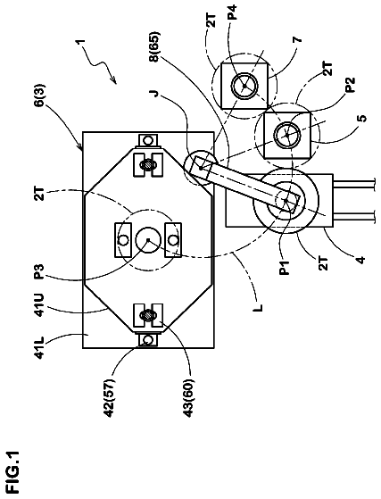
FIG. 1 is a view illustrating the outline of an overall configuration of a tire marking apparatus of an embodiment of the invention.
FIG. 2 is a block diagram of the tire marking apparatus.
FIG. 3 is a plan view of a conveying lane of the tire marking apparatus.
FIG. 4 is a front view of the wide conveying lane.
FIG. 5 is a view illustrating the internal structure of a first positioning unit of the wide conveying lane.
FIG. 6 is a perspective view of a driving roller of the first positioning unit.
FIG. 7 is a plan view of a holding arm and a rotational driving unit of the wide conveying lane.
FIG. 8 is a front view of a rotational amount detecting unit of the tire marking apparatus.
FIG. 9 is a front view when a head unit and a ribbon supplying mechanism of the tire marking apparatus are partially broken.
FIG. 10 is a cross-sectional view taken along cutting line A 1 -A 1 in FIG. 9 .
FIG. 11 is a front view of the ribbon supplying mechanism.
FIG. 12 is a view as viewed from the direction of arrow A 2 in FIG. 11 .
FIG. 13 is a sectional view of a first pulley of the ribbon supplying mechanism.
Description of embodiments
Hereinafter, an embodiment of a tire marking apparatus related to the invention will be described, referring to FIGS. 1 to 13 .
As illustrated in FIGS. 1 and 2 , a marking apparatus of the present embodiment is configured to perform marking (printing) in a tire T, includes a conveying unit 10 that supports and conveys the tire T from below, a head unit 80 that is arranged above the conveying unit 10 , a ribbon supplying mechanism 100 that is attached to the head unit 80 , and a control unit 140 that controls the conveying unit 10 , the head unit 80 , and the ribbon supplying mechanism 100 .
In addition, the head unit 80 and the ribbon supplying mechanism 100 constitute a printing device 2 . The marking apparatus 1 includes the printing device 2 .
As illustrated in FIGS. 3 and 4 , the conveying unit has a split conveying lane 15 in which a first conveying lane 16 A and a second conveying lane 16 B are arranged side by side in a width direction of the conveying unit 10 on an upstream side D 1 in the conveying direction D of the conveying unit 10 , and an wide conveying lane 30 that is arranged on a downstream side D 2 in the conveying unit 10 . Since the configurations of the first conveying lane 16 A and the second conveying lane 16 B are the same in the present embodiment, the configuration of the first conveying lane 16 A will be illustrated by adding the English capital letter “A” to figures or English lower case letters, and the configuration corresponding to the second conveying lane 16 B will be illustrated by adding the English capital letter “B” to figures or English lower case letters. Accordingly, overlapping description will be omitted. Positioning units 36 A and 36 B, printing pins 90 A to 90 H, and the like to be described below will be described similarly.
For example, the configurations of a first driving roller 17 A and a second driving roller 17 B (to be described below) of the first conveying lane 16 A are the same.
In the first conveying lane 16 A, each first driving roller 17 A and each first driven roller 18 A are rotatably supported by support members 19 A at both ends in the width direction around their respective axes 17 a A and 18 a A. The height of an upper surface of the first driving roller 17 A and the height of an upper surface of the first driven roller 18 A substantially coincide with each other, or the upper surface of the first driving roller 17 A is arranged to be slightly higher. The first driving roller 17 A and the first driven roller 18 A are alternately arranged along the conveying direction D. The first driving roller 17 A and the first driven roller 18 A are arranged on the same plane where the axes 17 a A and 18 a A are parallel to the horizontal plane.
A belt that is not illustrated is connected to the respective first driving rollers 17 A. A rotating shaft of a first roller driving motor 20 A illustrated in FIG. 2 is connected to this belt. The rotating shaft of the first roller driving motor 20 A can be driven so as to be switched to a normal direction (first direction) and a reverse direction (second direction). The first roller driving motor 20 A and a second roller driving motor 20 B constitute a conveyance driving unit 21 .
As illustrated in FIGS. 3 and 4 , the tire T is arranged on the respective first driving rollers 17 A, the respective first driven rollers 18 A, the respective second driving rollers 17 B, and the respective second driven rollers 18 B. In this case, the tire T is arranged so that a side surface of at least the first driving roller 17 A abuts against one side of a sidewall (printing surface) T 1 of the tire T with respect to an axis T 6 of the tire T and a side surface of the first driven roller 18 A auxiliarily abuts against the one side. The tire T is arranged so that a side surface of at least the second driving roller 17 B abuts against the other side of the sidewall T 1 with respect to the axis T 6 and a side surface of the second driven roller 18 B auxiliarily abuts against the other side. The rollers 17 A and 18 A and the rollers 17 B and 18 B abut against the one sidewall T 1 of the tire T, respectively.
By rotating the rotating shaft of the first roller driving motor 20 A in the normal direction, as illustrated in FIG. 3 , each first driving roller 17 A rotates in a normal direction F 1 around its axis 17 a A. By rotating the rotating shaft of the second roller driving motor 20 B in the normal direction, each second driving roller 17 B rotates in the normal direction F 1 around its axis 17 a B. In this case, the tire T arranged on the respective driving rollers 17 A and 17 B are conveyed from the upstream side D 1 toward the downstream side D 2 . Each first driven roller 18 A and each second driven roller 18 B that support the tire T to be conveyed performs the corotation of rotating according to the movement of the tire T.
In this way, the driving rollers 17 A and 17 B are rollers that rotationally drive the tire T, and the driven rollers 18 A and 18 B are rollers that are driven according to the rotating tire T.
On the other hand, if the rotating shafts of the roller driving motors 20 A and 20 B are rotated in the reverse direction, the first driving roller 17 A rotates in a reverse direction F 2 around its axis 17 a A, and the second driving roller 17 B rotates in the reverse direction F 2 around its axis 17 a B. In this case, the tire T arranged on the respective driving rollers 17 A and 17 B is conveyed from the downstream side D 2 toward the upstream side D 1 .
In the first conveying lane 16 A, as illustrated in FIGS. 3 and 4 , the pair of support members 19 A are connected together by a coupling member 24 A.
The coupling member 24 A is attached to a support member 26 A provided at a leg 25 A extending in an upward-downward direction. As a lower end of the leg 25 A is arranged on a floor surface (not illustrated), the first conveying lane 16 A is supported at a position separated upward from the floor surface.
The wide conveying lane 30 is configured similar to the wide conveying lanes 16 A and 16 B. That is, as illustrated in FIG. 3 , in the wide conveying lane 30 , each third driving roller 31 and each third driven roller 32 are supported by the support members 33 at both ends in the width direction so as to be rotatable around their respective axes 31 a and 32 a . The support members 33 are attached to the aforementioned support members 26 A and 26 B.
A belt that is not illustrated is connected to the respective third driving rollers 31 . A rotating shaft of a third roller driving motor 34 (refer to FIG. 2 ) is connected to this belt. The rotating shaft of the third roller driving motor 34 can be driven so as to be switched to the normal direction and the reverse direction.
The support member 26 A is provided with the first positioning unit 36 A.
In the first positioning unit 36 A, a pair of holding arms 38 A and 39 A are supported on a supporting base 37 A so as to be rotatable (rockable) about first ends of the holding arms 38 A and 39 A. The holding arms 38 A and 39 A can be rotated on a plane parallel to the horizontal plane about on their respective first ends via gears 40 A and 41 A by an arm driving cylinder 42 A (refer to FIG. 2 ). The holding arm 38 A is arranged closer to the downstream side D 2 than the holding arm 39 A.
As illustrated in FIG. 5 , a second end of the holding arm 38 A is provided with a columnar shaft member 38 a A. A driving roller 44 A illustrated in FIGS. 5 and 6 is rotatably supported by the shaft member 38 a A.
The driving roller 44 A is supported so as to be rotatable around an axis orthogonal to the horizontal plane.
As illustrated in FIGS. 5 and 6 , the driving roller 44 A has a cylindrical roller body 45 A, and a plurality of outside protrusions 46 A that protrude from an outer peripheral surface of the roller body 45 A and extend along an axis of the roller body 45 A.
The plurality of outside protrusions 46 A are arranged so as to be separated from each other in a circumferential direction of the roller body 45 A. The roller body 45 A and the outside protrusions 46 A that constitute the driving roller 44 A can be configured using a timing pulley made of steel, or can be integrally formed of resin, such as nylon or polyoxymethylene (POM).
As illustrated in FIG. 7 , a rotational driving unit 48 A for rotating the driving roller 44 A is attached to the holding arm 38 A.
The rotational driving unit 48 A, as illustrated in FIGS. 5 and 7 , has an air cylinder 50 A that is driven to move forward and backward on a straight line 49 A, a link member 51 A that is rotatably connected to a tip part of the air cylinder 50 A in a forward movement direction, and a well-known clutch mechanism 52 A that is attached to the link member 51 A. In addition, the link member 51 A and the clutch mechanism 52 A constitute a converting unit 53 A.
The air cylinder 50 A, as illustrated in FIG. 7 , is configured so that a rod (rod-shaped member) 50 b A is inserted into a cylinder body 50 a A so as to be capable of moving forward and backward with respect to the cylinder body 50 a A. A cylinder driving unit 50 c A (refer to FIG. 2 ), such as an air compressor, capable of supplying and discharging compressed air, is connected to the cylinder body 50 a A via a tube (not illustrated).
If compressed air is supplied to a head side within the cylinder body 50 a A by the cylinder driving unit 50 c A, the rod 50 b A moves forward with respect to the cylinder body 50 a A. On the other hand, if compressed air is supplied to a rod side within the cylinder body 50 a A by the cylinder driving unit 50 c A, the rod 50 b A moves backward with respect to the cylinder body 50 a A.
In addition, in the present embodiment, the air cylinder 50 A that is a linear motion part is driven with compressed air. However, the linear motion part may be driven with hydraulic pressure, magnetism, or the like.
A tip part of the rod 50 b A in the forward movement direction and a first end of the link member 51 A are rotatably connected together with a pin of which the reference sign is omitted.
As illustrated in FIG. 5 , a second end 51 a A of the link member 51 A is formed in a cylindrical shape. The shaft member 38 a A of the holding arm 38 A is inserted into a tube hole of the second end 51 a A so as to be rotatable with respect to the second end 51 a A. The aforementioned clutch mechanism 52 A is fixed to an outer peripheral surface of the second end 51 a A. The clutch mechanism 52 A is arranged within a tube hole of the roller body 45 A of the driving roller 44 A.
The clutch mechanism 52 A restricts that the driving roller 44 A rotates in a direction E 1 around an axis 38 b A of the shaft member 38 a A with respect to the clutch mechanism 52 A. On the other hand, the clutch mechanism allows the driving roller 44 A to rotate in a direction E 2 around the axis 38 b A with respect to the clutch mechanism 52 A.
In the rotational driving unit 48 A configured in this way, if the rod 50 b A moves forward as illustrated by a position P 3 of FIG. 7 with respect to the cylinder body 50 a A, the link member 51 A rotates in the direction E 2 around the axis 38 b A, and moves to a position P 4 . In this case, the clutch mechanism 52 A and the driving roller 44 A are connected together, and the clutch mechanism 52 A and the driving roller 44 A rotate in the direction E 2 around the axis 38 b A together with the second end 51 a A of the link member 51 A.
On the other hand, if the rod 50 b A has moved backward with respect to the cylinder body 50 a A, the link member 51 A rotates in the direction E 1 around the axis 38 b A. In this case, the connection between the clutch mechanism 52 A and the driving roller 44 A is released, and the driving roller 44 A does not rotate (idles).
In this way, the clutch mechanism 52 A allows the rotation of the driving roller 44 A only in the direction E 2 around the axis 38 b A with respect to the second end 51 a A of the link member 51 A.
The converting unit 53 A converts a force for the forward and backward movement driving of the air cylinder 50 A into the rotative force of the driving roller 44 A in the direction E 2 around the axis 38 b A.
The rotational driving unit 48 A includes the air cylinder 50 A and the converting unit 53 A, and the driving roller 44 A rotates in the direction E 2 by movement in which the air cylinder 50 A is driven to move forward and backward on the straight line 49 A being converted by the converting unit 53 A.
If the cylinder driving unit 50 c A performs forward movement and backward movement of the rod 50 b A, the driving roller 44 A rotates at a constant angle around the axis 38 b A.
y repeating a set of forward movement and backward movement of the rod 50 b A a predetermined number of times, so-called predetermined inching-driving in which the driving roller 44 A rotates a predetermined multiple number of times at a constant angle is performed.
A driven roller 57 A illustrated in FIG. 3 is rotatably supported by the second end of the holding arm 39 A. The driven roller 57 A is driven according to the tire T that rotated as will be described below. The support member 26 B is provided with a second positioning unit 36 B.
The first positioning unit 36 A and the second positioning units 36 B constitute a center position adjusting mechanism 59 .
The holding arm 38 B of the second positioning unit 36 B is arranged closer to the upstream side D 1 than the holding arm 39 B.
The first positioning unit 36 A and the second positioning unit 36 B are arranged so as to face each other the end of the split conveying lane 15 on the downstream side D 2 interposed therebetween.
In the center position adjusting mechanism 59 configured in this way, a tire detecting sensor 61 (refer to FIG. 2 ) detects that the tire T conveyed by the conveying unit 10 has arrived at a marking position P 1 specified between the first positioning unit 36 A and the second positioning unit 36 B. As the tire detecting sensor 61 , well-known contact type or non-contact-type sensors can be appropriately selected and used.
The tire detecting sensor 61 transmits the detection result to the control unit 140 .
When the tire detecting sensor 61 detects that the tire T has arrived at the marking position P 1 , the following control is performed.
In addition, at a normal time when the center position adjusting mechanism 59 does not adjust the position of the tire T, the holding arms 38 A, 39 A, 38 B, and 39 B are arranged so as to become parallel to the conveying direction D of the tire T, and there is no hindrance to conveyance of the tire T.
The arm drive motors 40 A, 41 A, 40 B, and 41 B are driven to rotate the holding arms 38 A, 39 A, 38 B, and 39 B to make the rollers 44 A, 57 A, 44 B, and 57 B abut against a tread T 2 of the tire T from a plurality of positions in the circumferential direction.
If the driving rollers 44 A and 44 B are rotated through inching-driving by the cylinder driving units 50 c A and 50 c B, the tire T rotates in a predetermined direction around the axis T 6 .
If the tire T rotates, the driven rollers 57 A and 57 B are driven and corotated.
The position of the axis T 6 of the tire T is adjusted (the tire T is aligned) by inching-driving the driving rollers 44 A and 44 B.
In this way, in the present embodiment, the driving rollers 44 A and 44 B of the center position adjusting mechanism 59 that adjusts the position of the tire T also serve as rotational position adjusting rollers that rotate the tire T around the axis T 6 .
As illustrated in FIG. 8 , a rotational amount detecting unit 65 is attached to the leg 25 A via a support member 64 .
In the rotational amount detecting unit 65 , a rotating shaft 68 is attached to a tip part of a rod 66 a of an air cylinder 66 via a coupling member 67 . The rod 66 a is inserted into a cylinder body 66 b of the air cylinder 66 so as to be capable of moving forward and backward. The cylinder body 66 b is fixed to the leg 25 A by the aforementioned support member 64 . A cylinder driving unit 70 (refer to FIG. 2 ) is connected to the cylinder body 66 b via a tube (not illustrated).
If compressed air is supplied to a head side within the cylinder body 66 b by the cylinder driving unit 70 , the rod 66 a moves forward with respect to the cylinder body 66 b . On the other hand, if compressed air is supplied to a rod side within the cylinder body 66 b by the cylinder driving unit 70 , the rod 66 a moves backward with respect to the cylinder body 66 b.
The rotating shaft 68 is arranged so as to be orthogonal to the horizontal plane. The rotating shaft 68 is supported by the coupling member 67 so as to be rotatable around an axis of the rotating shaft 68 .
A detection roller 71 is attached to a lower end of the rotating shaft 68 , and an encoder 72 is attached to an upper part of the rotating shaft. When the rod 66 a has moved forward, the detection roller 71 moves to a position P 5 , and a side surface of the detection roller 71 abuts against the tread T 2 of the tire T at the marking position P 1 . There is a constant relationship between the rotational amount (rotational angle) by which the tire T rotates around the axis T 6 and the rotational amount by which the rotating shaft 68 rotates around its axis.
The encoder 72 detects the rotational amount of the rotating shaft 68 and corrects the detection result to detect the rotational amount of the tire T. The encoder 72 transmits the detection result to the control unit 140 .
In the head unit 80 , as illustrated in FIGS. 1 and 9 , a base 82 is supported on a supporting base 81 . A coupling member 83 in which a through-hole 83 a is formed is attached to an upper part of the base 82 . The through-hole 83 a extends in the upward-downward direction.
As illustrated in FIG. 9 , a guide plate 84 is attached to a lower end of the base 82 . As illustrated in FIGS. 9 and 10 , a pair of through-holes 84 a are formed in the guide plate 84 . In addition, only the pair of through-holes 84 a in the guide plate 84 are illustrated in FIG. 10 .
The pitch of the pair of through-holes 84 a is equal to the pitch of printing pins adjacent to each other in a circumferential direction of a turntable 86 among printing pins 90 A to 90 H to be described below. In the upward-downward direction, the positions of the printing pins 90 A to 90 H or ink ribbons R 1 and R 2 (to be described below) that overlap the pair of through-holes 84 a are printing positions P 10 and P 11 . The printing positions P 10 and P 11 face the sidewall T 1 of the tire T arranged at the marking position P 1 .
A guide roller 85 for guiding the ink ribbons R 1 and R 2 to be described below is attached to the guide plate 84 .
A rod 87 attached on a central axis (rotational axis) 86 a of the disk-shaped turntable (disk part) 86 is inserted through the through-hole 83 a of the coupling member 83 so as to be rotatable with respect to the through-hole 83 a of the coupling member 83 .
Eight through-holes 86 b are formed at equal intervals around the central axis 86 a in the turntable 86 . The central axis 86 a of the turntable 86 is adjusted by an electrically-driven device (not illustrated) so as to be arranged substantially perpendicularly (also including perpendicularly) to the sidewall T 1 of the tire T at the marking position P 1 .
Heating means 86 c (refer to FIG. 2 ) having a heater or the like is arranged within the turntable 86 . The heating means 86 c applies predetermined electric power to the heater, thereby heating the printing pins 90 A to 90 H to be described below.
A motor or an air-indexing disk rotational driving device (disk driving unit) 88 , which rotates the turntable 86 around the central axis 86 a via the rod 87 , is attached to an upper end of the rod 87 . The disk rotational driving device 88 is fixed to the coupling member 83 . Eight printing pins 90 A to 90 H are arranged at equal intervals, that is, at every 45° around the central axis 86 a in the turntable 86 , as will be described below. For this reason, the disk rotational driving device 88 just has to rotate the turntable 86 in units of 45° that is a central angle with respect to the printing pins 90 A to 90 H adjacent to each other around the central axis 86 a.
Eight printing pins (printing parts) 90 A to 90 H are respectively inserted through the through-holes 86 b of the turntable 86 so as to be movable in the upward-downward direction. In addition, the printing pins 90 A to 90 H are short for the printing pins 90 A, 90 B, 90 C, 90 D, 90 E, 90 F, 90 G, and 90 H.
That is, the eight printing pins 90 A to 90 H are arranged at equal intervals around the central axis 86 a . As the eight printing pins 90 A to 90 H are arranged around the central axis 86 a , even if the number of printing pins included in the head unit 80 increases, the overall outer shape of the printing pins 90 A to 90 H is suppressed compared to a case where the printing pins 90 A to 90 H are linearly arranged.
The printing pin 90 A is configured such that diameter-enlarged parts 90 b A and 90 c A are provided at an upper end and a lower end of a rod-shaped pin body 90 a A (configurations corresponding to the pin body 90 a A and the diameter-enlarged parts 90 b A and 90 c A in the printing pins 90 B, 90 C, 90 E, 90 F, 90 G, and 90 H are not illustrated).
Although not illustrated, a shape protruding from a lower surface, such as a circular shape or a triangular shape, is formed in a lower surface of the pin body 90 a A. The pin body 90 a A is inserted through the through-hole 86 b of the turntable 86 . The diameter-enlarged parts 90 b A and 90 c A are respectively arranged above and below the turntable 86 .
A coil spring 91 A is arranged between a lower surface of the diameter-enlarged part 90 b A of the printing pin 90 A and an upper surface of the turntable 86 (coil springs 91 a B, 91 a C, 91 E, 91 F, 91 G and 91 H are not illustrated). The coil spring 91 A is inserted through the pin body 90 a A.
The coil spring 91 A biases the diameter-enlarged part 90 b A of the printing pin 90 A upward. In a state where an air cylinder 94 A (to be described below) does not bias the printing pin 90 A downward, a lower surface of the printing pin 90 A is arranged above the guide plate 84 .
Air cylinders 94 A and 94 B are attached to the coupling member 83 .
The air cylinder 94 A is configured so that a rod 94 b A is inserted into the cylinder body 94 a A so as to be capable of moving forward and backward in the upward-downward direction with respect to the cylinder body 94 a A (the cylinder body 94 a B and the rod 94 b B are not illustrated).
The cylinder body 94 a A is attached to the coupling member 83 . A cylinder driving unit 95 A (refer to FIG. 2 ) illustrated in FIG. 2 is connected to the cylinder body 94 a A via a tube (not illustrated). In addition, the air cylinders 94 A and 94 B and the cylinder driving units 95 A and 95 B constitute a printing driving unit 96 . The air cylinders 94 A and 94 B are arranged above the printing positions P 10 and P 11 .
If compressed air is supplied to a head side within the cylinder body 94 a A by the cylinder driving unit 95 A, the rod 94 b A moves downward with respect to the cylinder body 94 a A. In this case, the lower surface of the printing pin 90 A protrudes below the lower surface of the guide plate 84 by moving the printing pin 90 A forward against the biasing force of the coil spring 91 A.
When the heated printing pin 90 A presses the ink ribbon R 1 (to be described below) against the sidewall T 1 of the tire T, marking (printing) is performed in the tire T.
On the other hand, if compressed air is supplied to a rod side within the cylinder body 94 a A by the cylinder driving unit 95 A, the biasing force of the coil spring 91 A is received and the rod 94 b A upwardly moves backward with respect to the cylinder body 94 a A.
In this way, the printing pin 90 A is provided in the turntable 86 so as to be capable of moving forward and backward with respect to the sidewall T 1 of the tire T. The printing driving unit 96 simultaneously moves two printing pins, which are arranged at the printing positions P 10 and P 11 among the printing pins 90 A to 90 H, forward and backward.
The ribbon supplying mechanism 100 , as illustrated in FIG. 9 , has a ribbon supplying unit 101 and a ribbon winding unit 102 that are fixed to the base 82 of the head unit 80 .
The ribbon supplying unit 101 has a well-known configuration. In the ribbon supplying unit 101 , a first supply roller 106 and a second supply roller 107 are rotatably supported by an auxiliary base 105 fixed to the base 82 .
For example, a red ink ribbon R 1 is wound around the first supply roller 106 . A heat transfer type ribbon to which ink is transferred by being pressed and heated is used as the ink ribbon R 1 .
The ink ribbon R 1 pulled out and supplied from the first supply roller 106 is guided to the lower surface of the guide plate 84 after being wound around the guide roller 85 or the like so that constant tension acts on the ink ribbon R 1 . The ink ribbon R 1 passes through the printing position P 10 of the lower surface of the guide plate 84 . That is, the ink ribbon R 1 is arranged between the printing pin 90 A at the printing position P 10 and the tire T.
Similarly, for example, a yellow ink ribbon R 2 is wound around the second supply roller 107 . The ink ribbon R 2 pulled out and supplied from the second supply roller 107 is guided to the lower surface of the guide plate 84 after being wound around the guide roller 85 or the like so that constant tension acts on the ink ribbon R 2 . The ink ribbon R 2 passes through the printing position P 11 of the lower surface of the guide plate 84 .
Each of the ink ribbons R 1 and R 2 faces a lower surface of any one among the printing pins 90 A to 90 H across the through-holes 84 a of the guide plate 84 (refer to FIG. 10 ).
As illustrated in FIGS. 11 and 12 , in the ribbon winding unit 102 , a first winding roller 112 and a second winding roller 113 are rotatably supported by a support member 111 fixed to the base 82 of the head unit 80 . A roller driving unit 114 that rotates the first winding roller 112 and the second winding roller 113 is attached to the support member 111 .
The roller driving unit 114 has one winding motor (motor) 117 , a first pulley (first driven wheel) 118 coaxially attached to the first winding roller 112 , a second pulley (second driven wheel) 119 coaxially attached to the second winding roller 113 , and one belt (annular member) 120 connected to the first pulley 118 , the second pulley 119 , and a rotating shaft 117 b of the winding motor 117 , respectively.
The winding motor 117 is a motor in which the rotating shaft 117 b is rotatable in a normal direction F 6 and a reverse direction F 7 with respect to a motor body 117 a . The motor body 117 a is attached to the base 82 by the aforementioned support member 111 . A motor pulley 117 c is attached to the rotating shaft 117 b.
The first pulley 118 and the second pulley 119 are rotatably supported by the support member 111 . The motor pulley 117 c of the winding motor 117 , the first pulley 118 , and the second pulley 119 are rotatably supported on the same plane.
As illustrated in FIG. 13 , the first pulley 118 is attached to a shaft member 112 a of the first winding roller 112 via well-known first clutch mechanisms 122 a and 122 b and a well-known first bearing 123 . In addition, the first pulley 118 , the first clutch mechanisms 122 a and 122 b , and the belt 120 constitute a first transmission mechanism 124 . The shaft member 112 a is rotatably inserted through a through-hole (not illustrated) formed in the support member 111 .
The first clutch mechanism 122 a decouples the first pulley 118 from the shaft member 112 a in the direction F 8 and couples the first pulley 118 to the shaft member 112 a in the direction F 9 . Accordingly, the rotation of the shaft member 112 a in the direction F 8 around an axis 112 b with respect to the rotation of the first pulley 118 is restricted, and the rotation thereof in the direction F 9 is allowed.
At this time, the first clutch mechanism 122 b serves as a brake that restricts the rotation of the shaft member 112 a in the direction F 8 , while the first clutch mechanism allows the rotation of the shaft member in the direction F 9 .
The bearing 123 supports the shaft member 112 a so that the shaft member smoothly rotates with respect to the first pulley 118 .
The ink ribbon R 1 is wound around the first winding roller 112 .
The second pulley 119 is configured similar to the first pulley 118 . That is, as illustrated in FIG. 12 , the second pulley 119 is attached to a shaft member 113 a of the second winding roller 113 via second clutch mechanisms 126 a and 126 b and a bearing (not illustrated). In addition, the second pulley 119 , the second clutch mechanisms 126 a and 126 b , and the belt 120 constitute the second transmission mechanism 128 . The belt 120 serves as both the first transmission mechanism 124 and the second transmission mechanism 128 .
A direction in which the second clutch mechanism 126 a is coupled to the shaft member 113 a and rotates the shaft member 113 a is a direction reverse to that in the first clutch mechanism 122 a . That is, the second clutch mechanism 126 a decouples the second pulley 119 from the shaft member 113 a in a direction F 10 and couples the second pulley 119 to the shaft member 113 a in a direction F 11 . Accordingly, the rotation of the shaft member 113 a in the direction F 10 around an axis 113 b with respect to the rotation of the second pulley 119 is restricted, and the rotation thereof in a direction F 11 is allowed.
At this time, the second clutch mechanism 126 b serves as a brake that restricts the rotation of the shaft member 113 a in the direction F 10 , while the second clutch mechanism allows the rotation of the shaft member in the direction F 11 .
The second winding roller 113 is arranged at a position shifted in a width direction of the first winding roller 112 with respect to the first winding roller 112 . The ink ribbon R 2 is wound around the second winding roller 113 .
In order to enhance the tension that acts on the ink ribbon R 1 and the R 2 , a guide roller 130 is attached to the support member 111 .
The aforementioned belt 120 is wound around the motor pulley 117 c , the first pulley 118 , and the second pulley 119 . In order to enhance the tension that acts on the belt 120 , a guide pulley 131 is attached to the support member 111 .
In the ribbon supplying mechanism 100 configured in this way, if the rotating shaft 117 b of the winding motor 117 is rotated in the normal direction F 6 , the first pulley 118 rotates in the direction F 9 , and the second pulley 119 rotates in the direction F 10 . The first pulley 118 and the second pulley 119 are rotated via the belt 120 by the rotating shaft 117 b of the winding motor 117 .
In this case, the first pulley 118 and the shaft member 112 a are coupled together by the first clutch mechanism 122 a , and the first winding roller 112 rotates in the direction F 9 together with the first pulley 118 . Since the second pulley 119 and the second shaft member 113 a are decoupled in the second clutch mechanism 126 a , the second winding roller 113 does not rotate even if the second pulley 119 rotates in the direction F 10 .
That is, if the rotating shaft 117 b of the winding motor 117 is rotated in the normal direction F 6 , the ink ribbon R 1 is wound by the first winding roller 112 , but the ink ribbon R 2 is not wound. The ink ribbon R 1 is pulled out from the first supply roller 106 of the ribbon supplying unit 101 .
On the other hand, if the rotating shaft 117 b of the winding motor 117 is rotated in the reverse direction F 7 , the first pulley 118 rotates in the direction F 8 , and the second pulley 119 rotates in the direction F 11 . In this case, since the first pulley 118 and the shaft member 112 a are decoupled in the first clutch mechanism 122 a , the first winding roller 112 does not rotate even if the first pulley 118 rotates in the direction F 8 . The shaft member 113 a is coupled to the second clutch mechanism 126 a , and the second winding roller 113 rotates in the direction F 11 together with the second pulley 119 .
That is, if the rotating shaft 117 b of the winding motor 117 is rotated in the reverse direction F 7 , the ink ribbon R 2 is wound by the second winding roller 113 , but an ink ribbon R 2 does not rotate. The ink ribbon R 2 is pulled out from the second supply roller 107 .
In this way, the first transmission mechanism 124 transmits only the rotation of the rotating shaft 117 b of the winding motor 117 in the normal direction F 6 to the first winding roller 112 . Only when the rotating shaft 117 b rotates in the normal direction F 6 , the ink ribbon R 1 is wound by the first winding roller 112 .
The second transmission mechanism 128 transmits only the rotation of the rotating shaft 117 b of the winding motor 117 in the reverse direction F 7 to the second winding roller 113 . Only when the rotating shaft 117 b rotates in the reverse direction F 7 , the ink ribbon R 2 is wound by the second winding roller 113 .
A motor required in order to wind the ink ribbons R 1 and R 2 is one winding motor 117 .
The ribbon supplying mechanism 100 winds the ink ribbons R 1 and R 2 arranged between the printing pins 90 A and 90 H at the printing positions P 10 and P 11 and the tire T.
The description continues in the full USPTO document.
 Lapsed, fee not paid9 drawings