Technical field
This disclosure relates to a method and an apparatus for correcting the shape of a green tire having a side wall portions subjected to crush deformation locally the circumferential direction.
Background
Ordinarily, after the end of molding and before being carried into a vulcanizer, a green tire G is temporarily stored by hanging on two horizontal storage rods A, as illustrated in FIGS. 9 and 10 . However, if the green tire G is temporarily stored in such mode, there is a probability that base width of bead portions B (a spacing between a pair of bead portions B) varies in each green tire G depending on the way to carry the green tire G to the storage rods A, and circularity of the bead portions B during storage is deteriorated. However, if the green tire G is subjected to vulcanization when still in such state, qualities of the tire such as uniformity, balance and the like frequently suffer negative effects. In order to solve such problem, conventionally proposed is, for example, a disclosure in WO2005/046975A1 (PTL 1). CITATION LIST Patent Literature
Ptl1 wo2005/046975a1
This disclosure is made so that the width between the upper and lower bead portions B is corrected by moving first and second locking components in a radially expanding direction to correct by pressing lower and upper bead portions B on upper and lower sides of a green tire G to a circular shape at a predetermined diameter, while adjusting a distance between the first and the second locking components by lifting at least one of the lower and the upper bead correcting means up and down with a lifting means. Here, during the temporary storage of the green tire G, besides disorder of the base width of the bead portions B and/or deterioration of the circularity of the aforementioned green tire G, due to a large mass of a tread portion T, the tread portion T is lowered (hanged down) while maintaining the shape (circular shape) when being molded, crush deformation in radial direction (vertical direction) is generated locally in the circumferential direction of the side wall portions S, namely the side wall portion S located above the storage rods A, and the bead portions B at the portions where crush deformation is generated are spaced from each other and the base width of the bead portions B varies in a circumferential direction of the green tire G. SUMMARY Technical Problem
However, with respect to the aforementioned conventional shape correcting apparatus, there is a problem that although the base width and the circularity of the bead portions B can be corrected, the aforementioned crush deformation generated in a part of the side wall portions S cannot be corrected. Therefore, the green tire G is subjected to vulcanization while still in a state that crush deformation is generated in a part of the side wall portions S, and as a result, when the crush deformation on the side wall portions S is enlarged and cannot be eliminated during vulcanization, uniformity, in particular RFV (radial force variation) of the tire product is deteriorated. Moreover, recently, in response to the requirement on weight reduction of tire product, thickness lessening of side wall portions S is ongoing, but in this way, along with thickness lessening of side wall portions S, the level of the aforementioned crush deformation is further raised, and the aforementioned problem becomes more serious.
This disclosure is to provide a method and an apparatus for correcting the shape of a green tire, which is capable of effectively correcting such crush deformation and easily improving tire uniformity, even if a part of the side wall portion is subjected to crush deformation due to temporary storage. Solution to Problem
Such purpose can be achieved with an apparatus for correcting the shape of a green tire, which comprises: a pair of holders for holding a pair of bead portions of a green tire subjected to crushing deformation locally in a circumferential direction of a side wall portion, while maintaining a coaxial relation thereof; and a correcting means for correcting the shape of the green tire by applying a pressurized fluid to an inner chamber of the green tire with beads portions held by the pair of holders, setting a center axis of a tread portion of the green tire to be in accord with central axes of the pair of bead portions which are maintained in a coaxial relation, and deforming the side wall portions toward an outer side. The correcting means comprises a bladder to be set on a radially inner side of the pair of coaxial bead portions, coaxially with the center axis of the bead portions, wherein the bladder has a constant thickness and is configured so that, as the bladder is supplied with a pressurized fluid at a pressure no higher than an elongation initiating pressure of the bladder, the pressure is applied to the inner chamber of the green tire via the bladder, causing the bladder to be inflated and pressed against an inner surface of the tread portion and the side wall portions of the green tire.
Second, the purpose can be achieved with a method for correcting the shape of a green tire, comprising: holding a pair of bead portions of a green tire with a pair of holders while maintaining a coaxial relation therebetween, said green tire being subjected to crushing deformation in a part of a circumferential direction of side wall portions; and correcting the shape of the green tire by applying a pressurized fluid to an inner chamber of the green tire with the bead portions held by the pair of holders, setting a center axis of a tread portion of the green tire to be in accord with central axes of the pair of bead portions which are maintained in a coaxial relation, and deforming the side wall portions toward an outer side. Advantageous Effect
In this disclosure, the shape of the green tire is corrected by applying the pressurized fluid into the inner chamber of the green tire, with the bead portions held by the respective holders while being maintained in a coaxial relation, setting the central axis of the tread portion of the green tire to be in accord with the central axes of the pair of bead portions, and simultaneously deforming the side wall portion outward to thereby generate an internal tension in meridian direction of the side wall portion. Therefore, the crush deformation generated in a part of the side wall portion is effectively recovered before vulcanization. Thereby, it is possible to easily improve uniformity of a vulcanized tire product, and in particular, the method is effective to a tire having side wall portions that are thin and are subjected to serious crush deformation due to temporary storage. In addition, the crush deformation can be uniformly recovered and corrected by pressing the portions subjected to crush deformation on a side wall portion from the inner side.
With respect to the temporarily stored green tire, due to crush deformation on a part of the side wall portions, the shape of the green tire is deformed, but according to the features disclosed in claim 2 , it is possible to easily detect whether the holding is secure, even with respect to the aforementioned green tire. In addition, according to the features disclosed in claim 3 , it is possible to secure the holding of the lower side bead portion by the lower side holder (the lower holding claws), and simultaneously set the upper side and lower side bead portions to be coaxial easily and securely. Further, according to the features disclosed in claim 4 , it is possible to easily improve security of the operator with a simple structure, and according to the features disclosed in claim 5 , it is possible to simplify the structure.
Brief description of the drawings
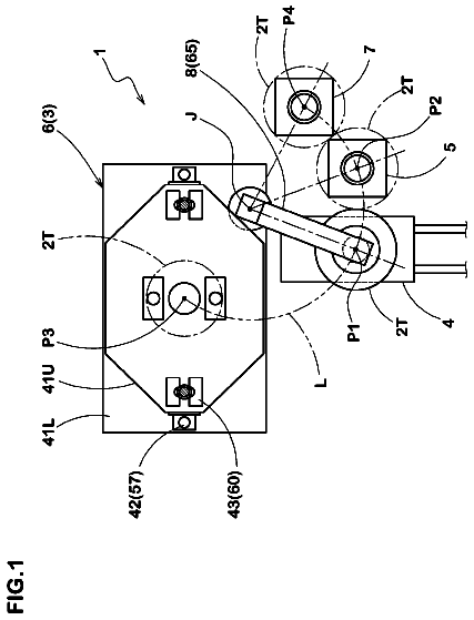
FIG. 1 is a schematic plan view showing Embodiment 1 of this disclosure;
FIG. 2 is a cross-sectional view as seen in the direction of arrows I-I of FIG. 1 ;
FIG. 3 is a front cross-sectional view showing a green tire as being held by an upper holder;
FIG. 4 is a partially-cut-away plan view showing the upper holder;
FIG. 5 is a partially-cut-away plan view showing a lower holder;
FIG. 6 is a front cross-sectional view showing a state that the green tire held by the holders is being corrected;
FIG. 7 is a partially-cut-away schematic front view showing Embodiment 2 of this disclosure;
FIG. 8 is a partially-cut-away schematic front view showing a green tire as being corrected;
FIG. 9 is a front view showing the green tire as being stored with storage rods; and
FIG. 10 is a cross-sectional view as seen in the direction of arrows II-II of FIG. 9 .
Detailed description
Embodiment 1 of this disclosure is described as follows based on Drawings.
In FIGS. 1 and 2 , represented by reference numeral 11 is a horizontal base. At a central portion of the base 11 , a lower end portion of a rotation shaft 13 extending vertically is rotatably supported via a bearing 14 . At an upper end of the rotation shaft 13 , a vertical rotation plate 15 in a discoid shape is fixed coaxially with the rotation shaft 13 , and on an upper surface of the rotation plate 15 , a plurality, herein 3 , of bearers 16 are disposed circumferentially at equal distances. Each bearer 16 is formed of a plurality of support pieces 17 having arc-shaped cross sections, the support pieces 17 being disposed circumferentially at an equal distance, and expanding upward with the lower ends thereof fixed to the rotation plate 15 .
Radial (vertical) crush deformation may be generated due to hanging on the storage rods A for the temporary storage as mentioned above, locally in the circumferential direction of a side wall portion S, i.e. the side wall portion S located above the storage rods A. In this instance, when the green tire G is carried onto the bearers 16 by an operator or a carrying means which is not illustrated, in a state where the part on the bead portions B subjected to the crush deformation are spaced from each other and the base width of the bead portions B varies in the circumferential direction of the green tire G, the green tire G is stored as being mounted on the bearers 16 horizontally (in a state where the rotation axis of the green tire G extends approximately vertically). Represented by reference numeral 20 is an external gear fixed to a rotation shaft 13 between the base 11 and the rotation plate 15 . This external gear 20 and an external gear 23 fixed on the output shaft 22 of a driving motor provided on the base 11 are in gear with each other. When the driving motor 21 functions and the rotation plate 15 rotates intermittently, the bearers 16 with the green tire G mounted thereon moves to a delivery position K directly below a directly-below position J mentioned in the following, and stores the green tire G at the delivery position K horizontally.
The aforementioned external gear 20 , driving motor 21 and external gear 23 , as a whole, constitute a moving mechanism 26 for moving a horizontal green tire G stored at any one of the bearers 16 . Further, in this disclosure, it is possible to dispose one or more bearers on a moving truck to store the green tire G horizontally, and move the moving truck, to thereby carry the green tire G stored on the bearers to the delivery position K. Moreover, in this disclosure, as the aforementioned moving mechanism 26 , a link mechanism or a cam mechanism can be used. Represented by reference numeral 27 is a vulcanization apparatus disposed on one side of the rotation plate 15 . When the green tire G is carried into this vulcanization apparatus 27 horizontally, the vulcanization apparatus 27 is closed and vulcanizes the green tire G into a tire product (a vulcanized tire).
Represented by reference numeral 30 is a carrying means for carrying the green tire G received from the bearers 16 to the vulcanization apparatus 27 . This carrying means is normally called a vertical loader. The carrying means 30 has a guide post 31 extending vertically, the guide post 31 having a fluid cylinder 32 connected therewith as a driving means extending parallel to the guide post 31 . Represented by reference numeral 33 is a liftable object supported slidably by the guide post 31 . This liftable object 33 has an end (upper end) of a piston rod of the fluid cylinder 32 connected therewith, and as a result, when the fluid cylinder 32 functions, the liftable object 33 is lifted up and down by being guided by the guide post 31 . Further, in this disclosure, as the aforementioned driving means, a screw mechanism, a rack-pinion mechanism or a chain mechanism can be used.
Represented by reference numeral 34 is a horizontal swing arm having a base end portion supported rotatably by the liftable object 33 . The base end portion of this swing arm 34 is penetrated by the guide post 31 . Represented by reference numeral 35 is a driving motor supported by the liftable object 33 . Driving power for rotation of this driving motor 35 is transferred to the base end portion of the swing arm 34 via an external gear which is not illustrated, and swings the swing arm 34 in a horizontal plane centered on the base end portion thereof (the guide post 31 ). The aforementioned driving motor 35 and external gear, as a whole, constitute a swing mechanism 36 for swinging the swing arm 34 , and in this disclosure, as the aforementioned swing mechanism 36 , a link mechanism or a cam mechanism can be used. The aforementioned fluid cylinder 32 as a driving means and the swing mechanism 36 , as a whole, constitute a moving means 37 for horizontally or vertically moving, i.e. three-dimensionally moving the upper holder mentioned below, the upper holder being disposed at an end portion of the swing arm 34 .
In FIGS. 1, 3 and 4 , at the end portion of the swing arm 34 , a horizontal support disc 38 in a discoid shape is fixed, and on the lower surface of this support disc 38 , an upper support plate 40 in a discoid shape coaxial with the support disc 38 via a bracket 39 is installed. On an upper surface of this upper support plate 40 , a plurality, herein 6 , of guide blocks 41 are disposed circumferentially at equal distances, and on these guide blocks 41 , horizontal portions 42 a of a plurality (a number the same as the guide blocks 41 ) of upper holding claws 42 are supported slidably, the upper holding claws 42 containing horizontal portions 42 a extending radially and vertical portions 42 b having an arc-shaped cross section, the vertical portions being located radially outer than a circumference of the upper support plate 40 and extend vertically downward from a radially outer end of the horizontal portions 42 a . At lower ends of the vertical portions 42 b of each upper holding claw 42 , locking portions 43 are formed, the locking portions 43 having cross sections in an approximately-triangular arc shape protruding outward radially, and these upper holding claws 42 can hold the green tire G from a radially inner side and from an axially inner side, when the upper holding claws 42 move synchronously and outward radially, to contact the locking portions 43 with an axially inner side surface of an upper side bead portion B of the green tire G.
At a radially outer side of the support disc 38 , a rotation ring 46 in a ring shape, which is coaxial with the support disc 38 , is rotatably and fittedly supported, the rotation ring 46 being connected with an end of the piston rod 48 of the fluid cylinder 47 , which contains an air cylinder, etc. disposed on the upper surface of the support disc 38 . Represented by reference numeral 49 is a plurality (a number the same as the upper holding claws 42 ) of transfer links, the transfer links having length-directional central portions connected rotatably with the support disc 38 via pins 50 and extend approximately radially, and long holes 51 formed on radially inner end portions of these transfer links 49 are inserted by pins 52 erected on the horizontal portions 42 a of each upper holding claw 42 . On the other hand, pins 53 protruding upward are fixed at radially outer end portions of each transfer link 49 , and these pins 53 are inserted into a plurality (a number the same as the transfer links 49 ) of long holes 54 , the long holes 54 being formed in the rotation ring 46 and extend radially.
As a result, when the fluid cylinder 47 functions and rotates the rotation ring 46 , the transfer links 49 swing synchronously centered on the pins 50 , while such synchronous swing of the transfer links 49 is transferred to the upper holding claws 42 via the pins 52 , and thereby, these upper holding claws 42 are guided by the guide blocks 41 and move synchronously and radially, to hold or release the upper holding claws 42 . The aforementioned guide blocks 41 , rotation ring 46 , fluid cylinder 47 , transfer links 49 and pins 50 , 52 , 53 , as a whole, constitute a synchronous moving mechanism 55 for moving the plurality of upper holding claws 42 synchronously and outward radially. Moreover, the aforementioned upper holding claws 42 and synchronous moving mechanism 55 , as a whole, constitute an upper holder 56 , as a holder on one side (upper side) for holding the upper side bead portion B of the green tire G.
Accordingly, in this embodiment, the upper holder 56 is formed of a part of the carrying means 30 (the vertical loader). Further, in the aforementioned embodiment, the green tire G on the bearer 16 , which was moved to the delivery position K, was held by the upper holder 56 , while in this disclosure, it is possible to set the rotation plate to be unrotatable, and move the upper holder 56 within a horizontal plane, to thereby hold the green tire G carried by any one of the bearers 16 . Additionally, due to function of the aforementioned moving means 37 , the upper holder 56 is lowered and the upper holding claws 42 are inserted into the green tire G stored at the bearer 16 from the upper side, and due to function of the synchronous moving mechanism 55 , the upper holding claws 42 are then moved synchronously and outward radially, and the lower end portions of the upper holding claws 42 (the vertical portions 42 b ) contact with the upper side bead portion B of the green tire G at a certified low contact pressure.
At this state, the fluid cylinder 32 of the moving means 37 functions to raise the swing arm 34 and the upper holder 56 , while in this case, the upper holding claws 42 are raised in slidable contact with the upper side bead portion B, and a hanging-down side of the upper bead portion B is pulled up by the locking portions 43 ; as a result, the locking portions 43 of all upper holding claws 42 become in contact with a surface at an axially outer side of the upper side bead portion B, and as illustrated in FIG. 3 , the upper side bead portion B is held by the upper holding claws 42 of the upper holder 56 and becomes horizontal, from an inner side, herein from a radially inner side and an axially inner side. Here, as mentioned above, the green tire G is subjected to crush deformation locally in the side wall portion S in a circumferential direction, and base width of the bead portions B varies along the circumferential direction. Therefore, a lower side bead portion B inclines with respect to a horizontal direction, resulting in that a central axis of the upper side bead portion B and a central axis of the lower side bead portion are not coaxial, but intersects at a certain angle. Further, in this case, if the upper side bead portion and the lower side bead portion deviate from each other radially, the aforementioned central axes of the upper and lower side bead portions B may become torsional.
Represented by reference numeral 60 are protruding pieces formed as a whole on every other upper holding claw 42 , more specifically, on circumferences of vertical central portions of the vertical portions 42 b at a radially outer side, and detecting sensors 61 for detecting the green tire G, herein for detecting the side wall portions S, are installed on lower surfaces of each protruding piece 60 , and these detecting sensors 61 are for detecting the presence/absence of the green tire G, and for detecting whether the upper side bead portion B of the green tire G are held at a defined state, in this embodiment, whether the upper side bead portion B is held horizontally as mentioned above, by detecting distances from the detecting sensors 61 to the green tire G (the side wall portions S). For example, when any one of the upper holding claws 42 fails to hold and the locking portion 43 of the upper holding claw 42 is in contact with a surface at a radially inner side or a surface at an axially outer side of the upper side bead portion B, the portion becomes lower than the other portions. When the detecting sensors 61 detect such state, the holding operation of the upper side bead portion B is repeated, or the operation is stopped, or a report is sent to the operator, etc. In this way, a plurality of detecting sensors 61 are spaced from each other in a circumferential direction on the upper holder 56 as one holder, and by disposing a plurality of detecting sensors 61 on the upper holder 56 in this way, even the shape of the green tire G is deformed, it is possible to simply detect whether the green tire G is securely held by the upper holder 56 .
Here, in this embodiment, proximity switches are used as the aforementioned detecting sensors 61 , while in this disclosure, it is possible as well to use ultrasound sensors, capacitance type displacement meters, laser displacement meters, etc. A guide post 63 is disposed extending vertically at a side other than the guide post 31 . This guide post 63 is penetrated by a base end portion of a horizontal swing arm 64 , and rotatably supports the same. Represented by reference numeral 65 is a driving motor supported by a support block 66 installed on the guide post 63 below the swing arm 64 . Driving power for rotation of this driving motor 65 is transferred to the base end portion of the swing arm 64 via an external gear which is not illustrated, and swings the swing arm 64 centered on the base end portion thereof (the guide post 63 ) in a horizontal plane. The aforementioned driving motor 65 and the external gear, as a whole, constitute a moving means 67 for moving the lower holder mentioned below along an arc between a directly-below position J, which is located directly below the upper holder 56 in an above position, and a standby position L at a predetermined distance from the directly-below position, by swinging the swing arm 64 , while in this disclosure, as the aforementioned moving means, a link mechanism or a cum mechanism can be used. In addition, in this disclosure, the lower holder can be moved along a straight line by a moving means.
In FIGS. 1, 3 and 5 , a horizontal lower support plate 70 in a discoid shape is installed at an end portion of the swing arm 64 , and on an upper surface of this lower support plate 70 , a plurality, herein 8 , of guide blocks 71 are disposed in a circumferential direction at equal distances. A plurality (a number the same as the guide blocks 71 ) of sliders 72 extending radially are supported slidably by these guide blocks 71 . Lower holding claws 73 extending vertically are fixed at radially outer ends of each slider 72 , and locking portions 74 protruding to outward radially and having cross sections in approximately-triangular arc shape are formed at upper ends of these lower holding claws 73 . In this way, a plurality of lower holding claws 73 having locking portions 74 formed on upper ends thereof are spaced from each other, and are supported so as to move synchronously and radially by a lower support plate 70 via the guide blocks 71 and the sliders 72 , the locking portions 74 protruding outward radially. Additionally, these lower holding claws 73 (locking portions 74 ) can hold the green tire G, when the sliders 72 move synchronously and outward radially, and contact with a surface on a radially inner side and a surface at an axially inner side of the lower side bead portion B of the green tire G.
Represented by reference numeral 77 is a transfer shaft extending vertically while penetrating the lower support plate 70 coaxially with the lower support plate 70 . A vertical central portion of this transfer shaft 77 is supported rotatably by the lower support plate 70 via a bearing 78 . Moreover, Represented by reference numeral 79 is a horizontal discoid cam plate fixed to an upper end of the transfer shaft 77 . A plurality (a number the same as the sliders 72 ) of cam grooves 80 are formed on this cam plate 79 in a circumferential direction at equal distances, the cam grooves 80 inclining in an identical direction with respect to radial directions, herein inclining from one side in a circumferential direction from a radially inner side to a radially outer side, to the other side in the circumferential direction. Represented by reference numeral 81 is a plurality (a number the same as the sliders 72 ) of pins fixed at lower end portions of each slider 72 and extending vertically, and upper end portions of these pins 81 are slidably inserted into the corresponding cam grooves 80 of the cam plate 79 . As a result, the transfer shaft 77 and the cam plate 79 rotate as a whole, and thereby, the pins 81 , the sliders 72 and the lower holding claws 73 are guided by the guide blocks 71 , to be pushed to inclining sides of the cam grooves 80 and moved radially.
Represented by reference numeral 84 is a rotary actuator installed on a lower surface of the lower support plate 70 to supply and exhaust compressed air at a certified pressure. An external gear 86 fixed to a rotation shaft 85 of this rotary actuator 84 is in gear with an external gear 87 fixed at a lower end portion of the transfer shaft 77 . As a result, the rotary actuator 84 functions and rotates the transfer shaft 77 , for moving a plurality of sliders 72 and lower holding claws 73 synchronously and radially to hold and release the lower holding claws 73 . The aforementioned guide blocks 71 , sliders 72 , transfer shaft 77 , cam plate 79 , pins 81 , rotary actuator 84 and external gears 86 , 87 , as a whole, constitute a synchronous moving mechanism 88 for moving the plurality of lower holding claws 73 synchronously and outward radially, and the aforementioned lower holding claws 73 and the synchronous moving mechanism 88 , as a whole, constitute a lower holder 89 , as a holder at the other side (the lower side) for holding the lower side bead portion B of the green tire G. Further, in this disclosure, as the aforementioned synchronous moving mechanism, a plurality of cylinders, a screw mechanism, etc. for moving the upper holding claws 42 and the lower holding claws 73 synchronously and radially can be used.
Additionally, as mentioned above, when the upper holder horizontally holds the upper bead portion B of the green tire G horizontally, the fluid cylinder 32 functions and raises the upper holder 56 to the above position higher than the directly-below position J together with the green tire G; the moving means 67 (the driving motor 65 ) then swings the swing arm 64 to move the lower holder 89 from the standby position L to the directly-below position J; next, the fluid cylinder 32 functions to lower the upper holder 56 together with the green tire G, and the lower end of the green tire G, herein the lower end bead portion B, contact with the upper surface of the lower support plate 70 . Then, as mentioned above, the side wall portion S of the green tire G is subjected to crush deformation locally in the circumferential direction, and the base width of the bead portions B varies in a circumferential direction. Therefore, as illustrated in FIG. 3 , the lower bead portion B inclines with respect to the upper surface of the horizontal lower support plate 70 , and only the part subjected to the most serious crush deformation of the lower side bead portion B of the side wall portion S is locally in contact with the lower support plate 70 . At this state, the synchronous moving mechanism 88 functions and moves the lower holding claws 73 synchronously and outward radially, to contact the lower holding claws 73 below the locking portions 74 with the lower side bead portion B at a certified low contact pressure.
The fluid cylinder 32 then functions to raise the upper holder 56 and the green tire G, as a whole, and thereby, the lower end bead portion B is raised while being slidably connected to the lower holding claws 73 . Then, a portion spaced above the lower support plate 70 of the lower side bead portion B, i.e., the bead portion B on the right side in FIG. 3 , contacts with the locking portions 74 at an early stage to regulate the rise thereof. However, as the upper holder 56 and the green tire G are further raised, and the portion, of which the rise is regulated by the locking portion 74 of the side wall portion S, is deformed so as to be gradually expanded. Additionally, the upper holder 56 and the green tire G are raised until an axially inner side surface of the lower side bead portion B contacts with the locking portions 74 of all lower holding claws 73 , and thereby, the lower side bead portion B becomes horizontal and parallel to the upper side bead portion B. In this way, the lower side bead portion B of the green tire G is held from the inner side of the lower holder 89 , herein from the radially inner side and the axially inner side. Then, in the correcting apparatus, of course the upper holder 56 and the lower holder 89 are assembled while maintaining a coaxial relation, and thus the upper and lower side bead portions B, which are held by these upper holding claws 42 of the upper holder 56 and the lower holding claws 73 of the lower holder 89 , become parallel and coaxial with each other, as mentioned above.
Further, in this disclosure, it is possible to omit the detecting sensors 61 disposed on the aforementioned upper holder 56 (the upper holding claws 42 ), and to dispose a plurality of detecting sensors the same as the detecting sensors 61 spaced from each other in a circumferential direction on the lower support plate 70 of the lower holder 89 ; or, in addition to the detecting sensors 61 , to dispose detecting sensors the same as the detecting sensors 61 spaced from each other in a circumferential direction on the lower support plate 70 of the lower holder 89 , for detecting the distances from the detective sensors to the green tire G by using these detecting sensors, and to thereby detect whether the bead portions B of the green tire G are held by the upper and lower holders 56 and 89 at a defined state. In this way, the upper holder 56 and the lower holder 89 are spaced vertically from each other, constituting a pair of holders for holding a pair of bead portions B of the green tire G while maintaining a coaxial relation. In addition, in this disclosure, it is possible to leave the lower holder 89 standing at the directly-below position J, and on the other hand, remove the lower holder 89 and simultaneously move the same in an inclined direction or in a crank-like manner, when lifting the upper holder 56 up and down between the delivery position K and an above position.
Here, the upper and lower side bead portions B of the green tire G are held from the radially inner side and the axially inner side by the aforementioned upper and lower holders 56 and 89 forming a pair, while in this disclosure, it is possible to hold the upper and lower side bead portions B of the green tire G by using a pair of holders from only the radially inner sides, or from the radially inner sides and the axially inner sides, or from both the radially inner sides and axially inner and outer sides. Moreover, in this embodiment, the fluid cylinder 32 functions as a driving means and lift one holder (the upper holder 56 ) up and down, herein moves the same in axial direction of the green tire G, to move the upper holder 56 and the lower holder 89 forming a pair toward or away from each other, while in this disclosure, it is possible to install the upper holder 56 on the guide post 31 so that the axial movement thereof is disabled, and on the other hand, to dispose a driving means the same as mentioned above for lifting the lower holder 89 up and down to move the lower holder 89 toward or away from the upper holder 56 , or to dispose a driving means to lift the lower holder 89 up and down in addition to the fluid cylinder 32 for lifting the upper holder 56 up and down, for lifting the upper and lower holders 56 and 89 forming a pair up and down to move the same relatively toward or away from each other. Further, in this embodiment, the horizontal green tire G (a pair of bead portions B) is held by a pair of holders, while in this disclosure, it is possible to hold a vertical (a state that the rotation axis of the green tire G is extending horizontally) green tire G with a pair of holders. In this case, a pair of holders relatively move toward and away from each other by moving horizontally.
It is possible to secure the holding of the lower side bead portion B by the lower holder 89 (the lower holding claws 73 ), and to simultaneously set the lower side bead portion B and the upper side bead portion B to be coaxial easily and securely, by spacing such upper and lower holders 56 and 89 forming a pair vertically from each other, and simultaneously lifting either holder, herein the upper holder 56 , up and down, to thereby dispose a driving means (the fluid cylinder 32 ) for moving the upper and lower holders 56 and 89 forming a pair toward and away from each other, and to set the lower holder 89 to have a horizontal lower support plate 70 and locking portions 74 formed thereon and to have a plurality of lower holding claws 73 spaced from each other in a circumferential direction, the locking portions 74 being supported so as to move synchronously and radially by the lower support plate 70 and protruding outward radially, and to further lower the horizontal green tire G, of which the upper side bead portion B is maintained in the horizontal state by the upper holder 56 , together with the upper holder 56 on the upper side as a whole, to contact with the lower support plate 70 , and then to move the lower holding claws 73 synchronously and outward radially to contact with the lower side bead portion B of the green tire G, and then to raise the upper holder 56 and the green tire G until the inner side surface of the lower side bead portion B contacts with the locking portions 74 of all lower holding claws 73 . Further, in this disclosure, it is possible to contact the lower holding claws 73 with the lower side bead portion B by moving the lower holding claws 73 synchronously and outward radially, and then synchronously lower all lower holding claws 73 until the locking portions 74 thereof contact with the inner side surface of the lower side bead portion B.
In addition, as mentioned above, by disposing the moving means 67 for moving the lower holder 89 between the directly-below position J, which is located directly below the upper holder 56 in an above position, and the directly-below position J, which is spaced from the standby position L horizontally at a predetermined distance, and simultaneously disposing the bearer 16 for storing the green tire G horizontally directly below the directly-below position J, to thereby lower the upper holder 56 and hold the upper side bead portion B of the green tire G stored at the bearer 16 , and then raise the upper holder 56 together with the green tire G to a position above the directly-below position J, and next move the lower holder 89 with the moving means 67 from the standby position L to the directly-below position J, and then lower the upper holder 56 together with the green tire G and hold the lower side bead portion B of the green tire G by using the lower holder 89 located at the directly-below position J, it is possible to easily apply the apparatus to an existing apparatus, and to easily improve security of operators.
Represented by reference numeral 91 is a plurality ( 3 ) of connecting rods erected on the upper surface of the lower support plate 70 , and these connecting rods 91 are extending vertically in a side radially outer than a circumference of the cam plate 79 , and are disposed in a circumferential direction at equal distances. A horizontal intermediate plate 92 located directly above the cam plate 79 is fixed at upper ends of these connecting rods, and a lower clamping 93 is installed removably on an upper surface of this intermediate plate 92 . In addition, a cylindrical support post 94 extending vertically is installed at an axial central portion of this lower clamping 93 , and a horizontal upper clamping 95 , which is in pair with the lower clamping 93 , is fixed to an upper end of this support post 94 while maintaining a coaxial relation with the lower clamping 93 . Represented by reference numeral 96 is a bladder formed of vulcanized rubber, with an upper end portion held by a circumferential portion of the upper clamping 95 . A lower end portion is held by a circumferential portion of the lower clamping 93 , while maintaining a sealed state. This bladder 96 is cylindrical when no load is applied, and is disposed on a radially inner side of the pair of bead portions (the upper and lower side bead portions B), the pair of bead portions being coaxial by being held by the upper and lower holders 56 and 89 , while maintaining a coaxial relation with the pair of bead portions B.
Here, by being held by the upper and lower holders 56 and 89 , an axial central portion of the bladder 96 overlaps a tread center of the green tire G axially, the green tire G having a pair of bead portions B coaxial with each other (having the same height). In addition, wall thickness t of the bladder 96 is equal at any position in the axial direction except for portions held by the lower and upper clampings 93 and 95 , and the value thereof is preferably within a range of 4 mm to 6 mm. Represented by reference numeral 98 is a path formed in the transfer shaft 77 . A lower end of this path 98 is connected to a pressurized fluid source or vacuum source for storing, for example, pressurized air, nitrogen gas, etc., via a connecting pipe which is not illustrated. In addition, the upper end of the path 98 is connected removably to a lower end of a connecting pipe 99 , and an upper end of this connecting pipe 99 penetrates the support post 94 and is connected to a sealed space 100 , the sealed space 100 being surrounded by the lower clamping 93 , the support post 94 , the upper clamping 95 and the bladder 96 .
The description continues in the full USPTO document.
 Lapsed, fee not paid6 drawings