 Lapsed, fee not paid1 drawing
Telecom & Networks · US 9,755,982 B2
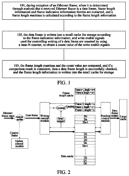
Method and apparatus for checking data frame length
A method and apparatus for checking a data frame length relate to an Ethernet passive optical network in the communication field.
US 9,755,984 B1 · Assignee: SYMANTEC CORPORATION · Inventors: Feroz; Azeem et al.
Sheet 1 of 12 from the published document. All sheets in the USPTO PDF
Methods, apparatuses and systems directed to an aggregate bandwidth utilization control scheme including fair share bandwidth allocation and dynamic allocation of bandwidth in response to detected traffic utilization. In one implementation, the present invention includes a weighted, fair share aggregate bandwidth allocation mechanism that dynamically responds to observed bandwidth utilization to provide unutilized or excess bandwidth to flows and partitions that require it. In another implementation, the present invention features a weighted fair share allocation scheme for hierarchical partition configurations. In other implementations, the present invention provides a per-flow target rate assignment mechanism that prevents spiraling decline of data flow rates.
Enterprises have become increasingly dependent on computer network infrastructures to provide services and accomplish mission-critical tasks. Indeed, the performance, security, and efficiency of these network infrastructures have become critical as enterprises increase their reliance on distributed computing environments and wide area computer networks. To that end, a variety of network devices have been created to provide data gathering, reporting, and/or operational functions, such as firewalls, gateways, packet capture devices, bandwidth management devices, application traffic monitoring devices, and the like. For example, the TCP/IP protocol suite, which is widely implemented throughout the world-wide data communications network environment called the Internet and many wide and local area networks, omits any explicit supervisory function over the rate of data transport over the vario
1 of 12 drawing sheets so far from the published document, cropped to the drawing. Every sheet is in the USPTO PDF.
What the patent claimed, word for word. All of it is now free to use.
The present invention relates to management of network resources and, more particularly, to methods, apparatuses and systems directed to an aggregate network resource utilization control mechanism.
Enterprises have become increasingly dependent on computer network infrastructures to provide services and accomplish mission-critical tasks. Indeed, the performance, security, and efficiency of these network infrastructures have become critical as enterprises increase their reliance on distributed computing environments and wide area computer networks. To that end, a variety of network devices have been created to provide data gathering, reporting, and/or operational functions, such as firewalls, gateways, packet capture devices, bandwidth management devices, application traffic monitoring devices, and the like. For example, the TCP/IP protocol suite, which is widely implemented throughout the world-wide data communications network environment called the Internet and many wide and local area networks, omits any explicit supervisory function over the rate of data transport over the various devices that comprise the network. While there are certain perceived advantages, this characteristic has the consequence of juxtaposing very high-speed packets and very low-speed packets in potential conflict and produces certain inefficiencies. Certain loading conditions degrade performance of networked applications and can even cause instabilities which could lead to overloads that could stop data transfer temporarily.
To facilitate monitoring, management and control of network environments, a variety of network devices, applications, technologies and services have been developed. For example, certain data flow rate control mechanisms have been developed to provide a means to control and optimize efficiency of data transfer as well as allocate available bandwidth among a variety of business enterprise functionalities. For example, U.S. Pat. No. 6,038,216 discloses a method for explicit data rate control in a packet-based network environment without data rate supervision. Data rate control directly moderates the rate of data transmission from a sending host, resulting in just-in-time data transmission to control inbound traffic and buffering of packets, and reduce the inefficiencies associated with dropped packets. Bandwidth management devices also allow for explicit data rate control for flows associated with a particular traffic classification. For example, U.S. Pat. No. 6,412,000, above, discloses automatic classification of network traffic for use in connection with bandwidth allocation mechanisms. U.S. Pat. No. 6,046,980 discloses systems and methods allowing for application layer control of bandwidth utilization in packet-based computer networks. For example, bandwidth management devices allow network administrators to specify policies operative to control and/or prioritize the bandwidth allocated to individual data flows according to traffic classifications. In addition, certain bandwidth management devices, as well as certain routers, allow network administrators to specify aggregate bandwidth utilization controls to divide available bandwidth into partitions. With some network devices, these partitions can be configured to provide a minimum bandwidth guarantee, and/or cap bandwidth, as to a particular class of traffic. An administrator specifies a traffic class (such as FTP data, or data flows involving a specific user or network application) and the size of the reserved virtual link—i.e., minimum guaranteed bandwidth and/or maximum bandwidth. Such partitions can be applied on a per-application basis (protecting and/or capping bandwidth for all traffic associated with an application) or a per-user basis (controlling, prioritizing, protecting and/or capping bandwidth for a particular user). In addition, certain bandwidth management devices allow administrators to define a partition hierarchy by configuring one or more partitions dividing the access link and further dividing the parent partitions into one or more child partitions. U.S. patent application Ser. No. 10/108,085 discloses data structures and methods for implementing a partition hierarchy.
Certain application traffic management devices, such as the PacketShaper® application traffic management device, offered by Packeteer®, Inc. of Cupertino, Calif., support the concurrent use of aggregate bandwidth policies (e.g., partitions), and per-flow bandwidth policies, such as rate policies enforced by the TCP Rate control technologies disclosed in U.S. Pat. No. 6,038,216. A partition is essentially a bandwidth allocation and queuing mechanism. That is, after a packet processor classifies each packet and pushes each packet onto a partition queue associated with the appropriate partition, another process, typically, loops through the partition queues to pop packets off the queues and populate an output queue. Aggregate bandwidth allocation among the different partitions essentially establishes a preference by which a flow control mechanism arbitrates among the corresponding partition queues. For example, a flow control module, while arbitrating among the partition queues, may read more packets from partitions having a higher allocation of bandwidth relative to partitions that have lower allocations. For example, as disclosed in U.S. application Ser. No. 10/108,085, incorporated by reference above, the bandwidth allocated to a given partition affects the rate at which the partition is selected by an output scheduling process and therefore the length of time packets are buffered in the corresponding partition queue. In addition, TCP Rate Control technologies can be used to effect per-flow rate policies to control or influence the rate at which packets are received at a network device and, therefore, use of inbound network bandwidth and the amount of data that is queued at any given time.
While partitions and per-flow rate policies are effective for their intended purposes, the configuration parameters that lead to their effective and predictable concurrent operation is often beyond the skill level of the average end user. For example, effective configuration of per-flow rate policies within a partition often requires a general knowledge of the typical number of data flows falling within the partition at given times. For example, a per-flow target rate is generally allocated based on an estimated rate demand for a given flow, regardless of the configuration of the partition that controls the flows in the aggregate. This per-flow target rate may be limited or adjusted by a per-flow rate policy configured by a user. In either case, these circumstances can result in significant underutilization of available bandwidth if the data flows do not actually consume their allocated rate, resulting in underutilization of the bandwidth allocated to the partition and the access link itself. Furthermore, use of explicit per-flow rate policies as the primary means of allocating per-flow bandwidth may not achieve a fair distribution of this bandwidth across the active flows in the partition.
In light of the foregoing, a need in the art exists for methods, apparatuses and systems directed to bandwidth control mechanism that addresses the problems discussed above. Embodiments of the present invention substantially fulfill this need.
The present invention provides methods, apparatuses and systems directed to an aggregate bandwidth utilization control scheme including fair share bandwidth allocation and dynamic allocation of bandwidth in response to detected traffic utilization. In one implementation, the present invention includes a weighted, fair share aggregate bandwidth allocation mechanism that dynamically responds to observed bandwidth utilization to provide unutilized or excess bandwidth to flows and partitions that require it. In another implementation, the present invention features a weighted fair share allocation scheme for hierarchical partition configurations. In other implementations, the present invention provides a per-flow target rate assignment mechanism that prevents spiraling decline of data flow rates. These and other aspects of various implementations of the present invention will become apparent from the drawings and description provided below.
FIG. 1 is a functional block diagram illustrating a computer network system architecture in which an embodiment of the present invention may operate.
FIG. 2 is a functional block diagram illustrating the functionality of a network application traffic management device, according to one implementation of the present invention.
FIG. 3 is a flow chart diagram showing a method, according to one implementation of the present invention, directed to processing data flows.
FIG. 4A is a flow chart diagram illustrating a process involving reading a packet onto a flow queue and a partition queue.
FIG. 4B is a flow chart diagram setting forth a process directed to re-computing a per-flow bandwidth allocation within a partition.
FIG. 4C is a flow chart diagram providing a method involving scheduling a packet for output from an application traffic management device.
FIG. 4D is a flow chart diagram illustrating the decisional logic associated with placing a flow queue onto a high priority or low priority partition queue.
FIG. 5 is a process flow diagram illustrating the overall process flow associated with the scheduling of packets for output.
FIG. 6 sets forth an exemplary hierarchical partition configuration according to an embodiment of the present invention.
FIG. 7 is a flow chart diagram illustrating operation of an aggregate bandwidth allocation daemon, according to one implementation of the present invention.
FIGS. 8A and 8B , together, are a flow chart diagram illustrating a method, according to one implementation of the present invention, directed to computing an aggregate bandwidth allocation among partitions.
FIGS. 9A thru 9 F illustrate hierarchical partition configurations according to various implementations of the present invention.
FIG. 1 illustrates an exemplary network environment in which embodiments of the present invention may operate. Of course, the present invention can be applied to a variety of network architectures. FIG. 1 illustrates, for didactic purposes, a network 50 , such as wide area network, interconnecting a first enterprise network 40 , supporting a central operating or headquarters facility, and a second enterprise network 40 a , supporting a branch office facility. Network 50 may also be operably connected to other networks, such as network 40 b , associated with the same administrative domain as networks 40 , 40 a , or a different administrative domain. As FIGS. 1 and 2 show, the first network 40 interconnects several TCP/IP end systems, including client devices 42 and server device 44 , and provides access to resources operably connected to computer network 50 via router 22 and access link 21 . Access link 21 is a physical and/or logical connection between two networks, such as computer network 50 and network 40 . The computer network environment, including network 40 and network 50 is a packet-based communications environment, employing TCP/IP protocols, and/or other suitable protocols, and has a plurality of interconnected digital packet transmission stations or routing nodes. First network 40 , and networks 40 a Et 40 b , can each be a local area network, a wide area network, or any other suitable network. As FIGS. 1 and 2 illustrate, application traffic management device 130 , in one implementation, is deployed at the edge of network 40 . As discussed more fully below, application traffic management device 130 is operative to classify and manage data flows traversing access link 21 . In one implementation, application traffic management device 130 also includes functionality operative to monitor the performance of the network (such as network latency) and/or network applications.
As FIG. 2 illustrates, network application traffic management device 130 , in one implementation, comprises network device application processor 75 , and first and second network interfaces 71 , 72 , which operably connect application traffic management device 130 to the communications path between router 22 and network 40 . Network device application processor 75 generally refers to the functionality implemented by application traffic management device 130 , such as network monitoring or reporting, application traffic management, and the like. In one embodiment, network device application processor 75 is a combination of hardware and software, such as a central processing unit, memory, a system bus, an operating system, device drivers, and one or more software modules implementing the functions performed by application traffic management device 130 . For didactic purposes, application traffic management device 130 is configured to manage network traffic traversing access link 21 . The above-identified patents and patent applications, incorporated by reference herein, disclose various functionalities and features that may be incorporated into application traffic management devices according to various implementations of the present invention.
In one embodiment, first and second network interfaces 71 , 72 are the hardware communications interfaces that receive and transmit packets over the computer network environment. In one implementation, first and second network interfaces 71 , 72 reside on separate network interface cards operably connected to the system bus of application traffic management device 130 . In another implementation, first and second network interfaces reside on the same network interface card. In addition, the first and second network interfaces 71 , 72 can be wired network interfaces, such as Ethernet (IEEE 802.3) interfaces, and/or wireless network interfaces, such as IEEE 802.11, BlueTooth, satellite-based interfaces, and the like. As FIG. 2 illustrates, application traffic management device 130 , in one embodiment, includes persistent memory 76 , such as a hard disk drive or other suitable memory device, such writable CD, DVD, or tape drives. In other implementations, application traffic management device 130 can include additional network interfaces, beyond network interfaces 71 and 72 , to support additional access links or other functionality. Furthermore, U.S. application Ser. No. 10/843,185 provides a description of the operation of various modules (according to one possible implementation of the present invention), such as network interface drivers, and data structures for receiving into memory and processing packets encountered at network interfaces 71 , 72 .
As FIG. 2 illustrates, network device application processor 75 , in one implementation, includes a packet processor 92 , flow control module 94 , and traffic classification engine 96 . Network device application processor 75 , in one implementation, further comprises host database 134 , flow database 135 , measurement engine 140 , management information base 138 , and administrator interface 150 . In one embodiment, the packet processor 92 is operative to process data packets, such as detecting new data flows, parsing the data packets for various attributes (such as source and destination addresses, and the like) and storing packet attributes in a buffer structure, and maintaining one or more flow variables or statistics (such as packet count, current rate, etc.) in connection with the data flows and/or the source/destination hosts. The traffic classification engine 96 , as discussed more fully below, is operative to classify data flows based on one or more attributes associated with the data flows. Traffic classification engine 96 , in one implementation, stores traffic classes associated with data flows encountered during operation of application traffic management device 130 , as well as manually created traffic classes configured by a network administrator, in a hierarchical traffic class structure. In one implementation, flow control module 94 is operative to apply aggregate and per-flow bandwidth utilization controls to data flows traversing the access link 21 in the inbound and/or outbound directions.
As discussed above, in one implementation, network device application processor 75 further comprises measurement engine 140 , management information base (MIB) 138 , and administrator interface 150 . Management information base 138 is a database of standard and extended network objects related to the operation of application traffic management device 130 . Measurement engine 140 maintains measurement and statistical data relating to operation of application traffic management device 130 to allow for monitoring of bandwidth utilization and network performance across access link 21 with respect to a plurality of bandwidth utilization and other network statistics on an aggregate and/or per-traffic-class level. In one implementation, measurement engine 140 tracks a variety of metrics corresponding to the partitions implemented by flow control module 94 . These metrics allow flow control module 94 , as discussed in more detail below, to dynamically adjust bandwidth allocations across flows and partitions to improve or manage network application performance.
Administrator interface 150 facilitates the configuration of application traffic management device 130 to adjust or change operational and configuration parameters associated with the device. For example, administrator interface 150 allows administrators to select identified traffic classes and associate them with traffic management policies, such as partitions. Administrator interface 150 also displays various views associated with a hierarchical traffic classification scheme and allows administrators to configure or revise the hierarchical traffic classification scheme. Administrator interface 150 can provide a command line interface and/or a graphical user interface accessible, for example, through a conventional browser on client device 42 .
A.1. Packet Processing
As discussed above, packet processor 92 , in one implementation, is operative to detect new data flows, instantiate data structures associated with the flows and parse packets to identify packet attributes, such as source and destination addresses, port numbers, etc., and populate one or more fields in the data structures. The U.S. Patents and patent applications identified above discuss the operation of packet processors that can be incorporated into embodiments of the present invention. In one embodiment, when packet processor 92 encounters a new data flow it stores the source and destination IP addresses contained in the packet headers in host database 134 . Packet processor 92 further constructs a control block (flow) object in flow database 135 including attributes characterizing a specific flow between two end systems, such as source and destination port numbers, etc. Other flow attributes in the flow object may include application specific attributes gleaned from layers above the TCP layer, such as codec identifiers for Voice over IP calls, Citrix database identifiers, and the like. Packet processor 92 also stores meta information relating to the received packets in a packet buffer—a memory space, typically in dynamic random access memory (DRAM), reserved for packets traversing application traffic management device 130 . In one embodiment, the packets are stored in the packet buffer with a wrapper including various information fields, such as the time the packet was received, the packet flow direction (inbound or outbound), and a pointer to the flow object corresponding to the flow of which the packet is a part.
In typical network deployments, the majority of data flows are generally TCP or UDP flows. However, any suitable transport layer flow can be recognized and detected. As discussed more fully below, in one embodiment, flows are identified based on the following flow attributes: 1) source IP address, 2) destination IP address, 3) source port number, 4) destination port number, and 5) protocol (derived from the “protocol” field in IPv4 headers, and the “NextHeader” field in IPv6 headers). One skilled in the art will recognize that flows can be identified in relation to a variety of attributes and combinations of attributes. In addition, methods for determining new data flows and assigning packets to existing data flows are well known in the art and also depend on the particular transport layer protocol employed. For a TCP flow, for example, packet processor 92 can determine a new data flow by detecting SYN, SYN/ACK, and/or ACK packets. However, a new data flow, depending on the network protocol associated with the flow, can simply be a data flow for which there is no corresponding flow object. For example, with UDP and GRE flows (where there is no explicit connection or handshake mechanism, such as SYN packets), a new flow is recognized by associating the source and destination addresses and port numbers to the flow and the flow type (e.g., UDP, GRE, etc.). Accordingly, when a UDP packet identifies a new address/port pair, the attributes discussed above are stored in a data structure along with the time of last packet. A new UDP flow between the same address/port pairs can be determined by comparing the last packet time to a threshold value (e.g., 2 minutes). If the difference between the time of the last packet and the time of the current packet is greater than the threshold, the current packet is deemed part of a new flow. In another implementation, a background and/or separate process can periodically compare the last packet times associated with a flow to a threshold period of time and deem the flow terminated if the last packet time is beyond the threshold period of time. The termination of TCP connections is typically detected by identifying FIN packets; however, the timeout mechanisms discussed above can be used in situations where a FIN packet is not detected.
In one embodiment, a control block (flow) object contains a flow specification object including such attributes as pointers to the “inside” and “outside” IP addresses in host database 134 , as well as other flow specification parameters, such as inside and outside port numbers, service type (see below), protocol type and other parameters characterizing the data flow. In one embodiment, such parameters can include information gleaned from examination of data within layers 2 through 7 of the OSI reference model. U.S. Pat. No. 6,046,980 and U.S. Pat. No. 6,591,299, as well as others incorporated by reference herein, disclose classification of data flows for use in a packet-based communications environment. FIGS. 1 and 2 illustrate the concept associated with inside and outside addresses, where network interface 71 is the “inside” network interface and network interface 72 is the “outside” network interface. As discussed above, in one embodiment, a flow specification object includes an “inside” and “outside” address relative to application traffic management device 130 . See FIG. 1 . For a TCP/IP packet, packet processor 92 can compute the inside and outside addresses based on the source and destination network addresses of the packet and the direction of the packet flow. Still further, packet processor 92 can also identify which host is the client and which host is the server for a given data flow and store this information in the flow specification or flow object. The identification of a server or client in a given transaction generally depends on the network protocols employed by the hosts. For example, in TCP flows, a client initiates a transaction by transmitting a SYN packet to initiate a TCP connection. Application traffic management device 130 can detect the SYN packet and note the source network address of the packet as the client host, and the destination address as the server host. One of ordinary skill in the art will recognize how to identify clients and servers in connection with other networking protocols.
In one embodiment, packet processor 92 creates and stores flow objects corresponding to data flows in flow database 135 . In one embodiment, flow object attributes include a pointer to a corresponding flow specification object, as well as other flow state parameters, such as TCP connection status, timing of last packets in the inbound and outbound directions, speed information, apparent round trip time, packet count, etc. Flow object attributes further include at least one traffic class identifier (or pointer(s) thereto) associated with the data flow, as well as policy parameters (or pointers thereto) corresponding to the identified traffic class. In one embodiment, flow objects further include a list of traffic classes for which measurement data (maintained by measurement engine 140 ) associated with the data flow should be logged. In one embodiment, to facilitate association of an existing flow object to subsequent packets associated with a data flow or connection, flow database 135 further maintains a control block hash table including a key comprising a hashed value computed from a string comprising the inside IP address, outside IP address, inside port number, outside port number, and protocol type (e.g., TCP, UDP, etc.) associated with a pointer to the corresponding flow object. According to this embodiment, to identify whether a flow object exists for a given data flow, packet processor 92 hashes the values identified above and scans the hash table for a matching entry. If one exists, packet processor 92 associates the pointer to the corresponding flow object with the packets in the data flow.
A.2. Traffic Classification Engine
As discussed above, traffic classification engine 96 , in one implementation, is operative to classify data flows into one of a plurality of traffic classes. Traffic classification engine 96 , in one implementation, comprises a plurality of service type identification modules, each of which correspond to a set of service types. Each service type identification module analyzes one or more packets in a given data flow to attempt to identify a service type corresponding to the flow. A service type, in one implementation, can be a network protocol, a service, or a network-application. For example, one service type identification module can correspond to a network application, such as Citrix®, while another service type identification module can be dedicated to detecting Oracle® or PostgreSQL database traffic. Still other service type identification modules can classify HTTP flows, FTP flows, ICMP flows, RTP flows, NNTP, SMTP, SSL, DICOM and the like. In one implementation, traffic classification engine 96 passes pointers to received packets to each service type identification module, which then inspect the packets stored in the buffer memory. In one implementation, each service type identification module has an associated packet count threshold (in the aggregate, packets from server to client, or client to server) after which it no longer attempts to classify a data flow. In one implementation, the packet count threshold will vary across the service type identification modules. For example, a service type identification module dedicated to classifying Citrix® traffic may be able to classify a data flow with certainty after three packets. In many instances, application traffic management device 130 may have to encounter more than one packet corresponding to a data flow in order to finally classify the data flow. For example, the initial TCP handshake packets may only reveal IP address, port numbers and protocol identifiers. While this information may be sufficient to identify HTTP traffic, for example, additional packets (such as data packets) may reveal a more specific network application, such as an accounting application or peer-to-peer file sharing application, that utilizes HTTP. Accordingly, in one implementation, each service type identification module responds to receiving a pointer to a packet by 1) reporting a matching service type identifier and the desire to inspect more packets in the flow (to possibly identify a more specific service type identifier); 2) reporting a matching service type and no interest in inspecting subsequent packets in the flow; 3) reporting no matching service type identifier and the desire to inspect more packets in the flow; and 4) reporting no matching service type and no interest in inspecting subsequent packets in the flow.
To allow for identification of service types (e.g., FTP, HTTP, etc.), traffic classification engine 96 , in one embodiment, is supported by one to a plurality of service identification tables in a relational database that allow for identification of a particular service type (e.g., application, protocol, etc.) based on the attributes of a particular data flow. Of course, other suitable data structures can be used to support the identification of service types, such as a set of hard-coded instructions, an XML file, and the like. In one embodiment, a services table including the following fields: 1) service ID, 2) service aggregate (if any), 3) name of service, 4) service attributes (e.g., port number, outside IP address, etc.), and a 5) default bandwidth management policy. A service aggregate encompasses a combination of individual services (each including different matching criteria, such as different port numbers, etc.) corresponding to the service aggregate. When application traffic management device 130 encounters a new flow, the service type identification modules of traffic classification engine 96 analyze the data flow against the service attributes in their respective services tables to identify a service ID corresponding to the flow. In one embodiment, traffic classification engine 96 may identify more than one service ID associated with the flow. In this instance, traffic classification engine 96 associates the more/most specific service ID to the flow. For example, network traffic associated with a peer-to-peer file sharing service may be identified according to a network protocol, such as TCP or HTTP traffic, as well as higher level, application-specific traffic types such as the actual file sharing application itself (e.g., Napster, Morpheus, etc.). In this instance, traffic classification engine 96 associates the flow with the most specific service ID. As a further example, an RTSP application data flow can be further classified to RTSP-Broadcast or RTSP-REALNET-TCP in the middle of the flow after a particular signature in the packets is encountered. In one implementation, traffic classification engine 96 writes the identified service type ID into the control block (flow) object corresponding to the data flow.
As discussed more fully below, service type identification, in one implementation, is a preliminary operation to the classification of a data flow according to the hierarchical traffic classification scheme configured by a network administrator. For example, a traffic class maintained by traffic classification engine 96 may be configured to include matching rules based on the service IDs in the services table. For example, a matching rule directed to HTTP traffic may simply refer to the corresponding service ID, as opposed to the individual attributes that the service type identification modules uses to initially identify the service. This implementation allows for a variety of hierarchical traffic classification configurations, such as the configuration of child traffic classes that further classify HTTP traffic on the basis of a network application, a range of IP addresses, and the like. Still further, the service type identifiers can correspond to a specific network application (e.g., Napster, Citrix, NetIQ, Oracle, Skype, etc.) and more generally to network protocols or services, such as IP, TCP, HTTP, SOAP, XML, UDP, FTP, SMTP, FTP, UDP, etc. As discussed more fully below, in one implementation, traffic classification engine 96 triggers operation of host probing module 97 for a given data flow, if a service type identifier corresponding to a network application (as opposed to a protocol or service) is not identified within a threshold number of packets.
A traffic class comprises a set of matching rules or attributes allowing for logical grouping of data flows that share the same characteristic or set of characteristics. In one implementation, the matching rules can correspond to the service type identifiers discussed above, as well as other data flow attributes, such as the network interface on which the packets are received by application traffic management device 130 , whether the server is the inside or outside host (see above), non-standard and standard port numbers, host IP address or subnet, MAC address, application-specific strings, diffserv codes, MPLS tags, VLAN tags, and the like. In one embodiment, each traffic class has at least one attribute defining the criterion(ia) used for identifying a specific traffic class. In one implementation, the attributes defining a given traffic class can be based on explicitly presented attributes of one or more packets corresponding to a data flow (as discussed above), or be based on behavioral attributes of the end systems associated with the flow. The U.S. patent applications identified above disclose various network traffic classification mechanisms that can be incorporated into embodiments of the present invention. For example, a traffic class can be defined by configuring an attribute defining a particular IP address or subnet. Of course, a particular traffic class can be defined in relation to a plurality of related and/or orthogonal data flow attributes. U.S. Pat. Nos. 6,412,000 and 6,591,299, and U.S. patent application Ser. No. 10/039,992 describe some of the data flow attributes that may be used to define a traffic class, as well as the use of hierarchical classification structures to associate traffic classes to data flows. In one embodiment, application traffic management device 130 includes functionality allowing for classification of network traffic based on information from layers 2 to 7 of the OSI reference model. Application traffic management device 130 can be configured to include matching rules that define a plurality of network applications commonly found in enterprise networks, such as database applications, Citrix® flows, ERP applications, and the like. As discussed below, the matching rules or attributes for a traffic class may be based on various types of node behavior, such as the number of concurrent connections of the inside or outside host.
In one embodiment, application traffic management device 130 is configured to include a predefined set of traffic classes based upon a knowledge base gleaned from observation of common or known traffic types on current networks. Application traffic management device 130 , in one embodiment, also allows an administrator to manually create a traffic class by specifying a set of matching attributes. As discussed above, administrator interface 150 , in one embodiment, allows for selection of a traffic class and the configuration of traffic management policies for the selected traffic class. Administrator interface 150 , in one embodiment, also allows for the selection and arrangement of traffic classes into hierarchical reference trees. In one embodiment, traffic classification engine 96 also stores traffic classes added by the traffic discovery module. Furthermore, as discussed below, application traffic management device 130 may also include traffic class discovery functionality that automatically adds traffic classes to traffic classification engine 96 in response to data flows traversing the device. Automatic network traffic discovery and classification (see below) is disclosed in U.S. Pat. Nos. 6,412,000, 6,457,051, and 6,591,299, which are incorporated herein by reference.
Traffic classification engine 96 , in one implementation, stores traffic classes associated with data flows that traverse access link 21 . Traffic classification engine 96 , in one embodiment, stores the traffic classes and corresponding data (e.g., matching rules, policies, partition pointers, etc.) related to each traffic class in a hierarchical tree. This tree is organized to show parent-child relationships—that is, a particular traffic class may have one or more subordinate child traffic classes with more specific characteristics (matching rules) than the parent class. For example, at one level a traffic class may be configured to define a particular user group or subnet, while additional child traffic classes can be configured to identify specific application traffic associated with the user group or subnet. U.S. application Ser. No. 10/334,467, as well as other patents and patent applications identified above, disclose how traffic classification engine 96 traverses the hierarchical tree to match a data flow to a leaf traffic class node.
In one embodiment, the root traffic classifications are “/Inbound” and “/Outbound” data flows. Any data flow not explicitly classified is classified as “/Inbound/Default” or “/Outbound/Default”. In other implementations, the concept of “inbound” and “outbound” is replaced by a set of policies corresponding to pairs of network interfaces, such as interfaces 71 and 72 , and the direction of packet traffic. For example, packets flowing from network interface 71 to network interface 72 (and vice versa) can be classified on that basis to eliminate any potential restrictions on classification of data flows in different network topologies. A “LocalHost” traffic class, in one implementation, corresponds to packets and data flows destined for application traffic management device 130 , such as requests for stored measurement data, traffic class mapping packets, or device configuration changes. In one embodiment, traffic classification engine 96 attempts to match to a leaf traffic class node before proceeding to remaining traffic class nodes in the hierarchical configuration. If a traffic class is found, the traffic classification engine 96 stops the instant search process and returns the identified traffic classification. Of course, one skilled in the art will recognize that alternative ways for traversing the hierarchical traffic class configuration can be implemented. For example, traffic classification engine 96 may be configured to traverse all traffic class nodes at a given level before proceeding to lower levels of the traffic classification tree.
The description continues in the full USPTO document.
About 5,826 words. The USPTO PDF has it with every drawing.
Fees are due 3.5, 7.5 and 11.5 years after grant. This patent expired on September 5, 2025, so the fee marked "not paid" was the one that went unpaid.
Aggregate network resource utilization control scheme
Filed Feb 2005 · granted Nov 2008Aggregate network resource utilization control scheme
Filed Oct 2008 · granted Sep 2017Earlier publications, parents and continuations. None of them can still be enforced, or this patent would not be listed.
Prior art cited by the examiner or applicant. Useful when you check your own idea for novelty.
Everything on this page comes from the documents linked above.


