Background of the invention
Field of the Invention
The present invention relates to an image processing apparatus, an image capturing apparatus, an image generation apparatus, and an image processing method, and relates particularly to a technique for correcting a distortion of a captured image that is caused by a shake of an image capturing apparatus.
Description of the Related Art
In recent years, CMOS image sensors that serve as an image sensor for use in an image capturing apparatus have become rapidly widespread. When an CMOS image sensor is used to shoot a moving image, a readout method in which accumulated electric charges are sequentially read out one line after another from the upper section to the lower section of the CMOS image sensor is widely used. This readout method is referred to as a rolling shutter method, and has a feature that readout timings are different between the upper and lower sections of the image sensor. Due to this feature, when the image capturing apparatus is shaken and the position of a subject on the image sensing surface is moved, a distortion (rolling shutter distortion) resulting from a difference in charge readout timing of the image sensor occurs in a captured image.
Various types of methods for correcting such a rolling shutter distortion by image processing have been proposed. Japanese Patent Laid-Open No. 2011-114649 discloses a technique for correcting, when a rolling shutter distortion correction amount exceeds a correction limit, only a part of the occurring rolling shutter distortion.
However, when performing control for correcting only a part of a rolling shutter distortion as described in Japanese Patent Laid-Open No. 2011-114649, the following problems will occur. That is, a rolling shutter distortion exceeds a correction limit mainly when the image capturing apparatus is in a panning state. In panning a moving image, even when only a part of a rolling shutter distortion is corrected, the residual uncorrected rolling shutter distortion is hardly noticeable under the movement of the video picture in the panning.
Meanwhile, currently, most image capturing apparatuses capable of shooting a moving image have a function to generate a still image from each of frame images constituting the moving image. When this function is used to generate a still image, the residual uncorrected rolling shutter distortion will significantly reduce the quality of the still image.
Summary of the invention
The present invention has been made in consideration of the above situation, and prevents a reduction in the quality of a still image generated from a frame image of a moving image shot by an image capturing apparatus, even when a rolling shutter distortion partially remains uncorrected.
According to the present invention, provided is an image processing apparatus that records a moving image used for generating a still image by a generation unit, comprising: a correction amount calculation unit configured to calculate, for each frame of the moving image, a correction amount for correction of a rolling shutter distortion of an image signal based on a shake amount detected by a camera shake amount detection unit; and a recording unit configured to record the correction amount in association with an image for each frame of the moving image, wherein the generation unit corrects an image of a selected frame from among the images of the frames based on the associated correction amount, and generates a still image.
Further, according to the present invention, provided is an image processing apparatus that records a moving image used for generating a still image by a generation unit, comprising: a correction amount calculation unit configured to calculate, for each frame of the moving image, a correction amount for correction of a rolling shutter distortion of an image signal based on a shake amount detected by a camera shake amount detection unit; a correction unit configured to correct, for each frame, the rolling shutter distortion based on the correction amount; a residual correction amount calculation unit configured to calculate, for each frame, a residual correction amount, which is an amount of the rolling shutter distortion that is not corrected by the correction unit; and a recording unit configured to record the residual correction amount in association with an image for each frame of the moving image, wherein the generation unit corrects an image of a selected frame from among the images of the frames based on the associated residual correction amount, and generates a still image.
Furthermore, according to the present invention, provided is an image capturing apparatus comprising: an image sensor; and an image processing apparatus that records a moving image used for generating a still image by a generation unit, and comprises: a correction amount calculation unit configured to calculate, for each frame of the moving image, a correction amount for correction of a rolling shutter distortion of an image signal based on a shake amount detected by a camera shake amount detection unit; and a recording unit configured to record the correction amount in association with an image for each frame of the moving image, wherein the generation unit corrects an image of a selected frame from among the images of the frames based on the associated correction amount, and generates a still image.
Further, according to the present invention, provided is an image capturing apparatus comprising: an image sensor; and an image processing apparatus that records a moving image used for generating a still image by a generation unit and comprises: a correction amount calculation unit configured to calculate, for each frame of the moving image, a correction amount for correction of a rolling shutter distortion of an image signal based on a shake amount detected by a camera shake amount detection unit; a correction unit configured to correct, for each frame, the rolling shutter distortion based on the correction amount; a residual correction amount calculation unit configured to calculate, for each frame, a residual correction amount, which is an amount of the rolling shutter distortion that is not corrected by the correction unit; and a recording unit configured to record the residual correction amount in association with an image for each frame of the moving image, wherein the generation unit corrects an image of a selected frame from among the images of the frames based on the associated residual correction amount, and generates a still image.
Further, according to the present invention, provided is an image generation apparatus that generates a still image from each frame image of a moving image recorded by an image processing apparatus that records a moving image used for generating a still image by a generation unit, and comprises: a correction amount calculation unit configured to calculate, for each frame of the moving image, a correction amount for correction of a rolling shutter distortion of an image signal based on a shake amount detected by a camera shake amount detection unit; and a recording unit configured to record the correction amount in association with an image for each frame of the moving image, wherein the generation unit corrects an image of a selected frame from among the images of the frames based on the associated correction amount, and generates a still image.
Further, according to the present invention, provided is an image generation apparatus that generates a still image from each frame image of a moving image recorded by an image processing apparatus that records a moving image used for generating a still image by a generation unit and comprises: a correction amount calculation unit configured to calculate, for each frame of the moving image, a correction amount for correction of a rolling shutter distortion of an image signal based on a shake amount detected by a camera shake amount detection unit; a correction unit configured to correct, for each frame, the rolling shutter distortion based on the correction amount; a residual correction amount calculation unit configured to calculate, for each frame, a residual correction amount, which is an amount of the rolling shutter distortion that is not corrected by the correction unit; and a recording unit configured to record the residual correction amount in association with an image for each frame of the moving image, wherein the generation unit corrects an image of a selected frame from among the images of the frames based on the associated residual correction amount, and generates a still image.
Further, according to the present invention, provided is an image processing method in which a moving image used for generating a still image is recorded, the method comprising: calculating, for each frame of the moving image, a correction amount for correction of a rolling shutter distortion of an image signal based on a shake amount detected by a camera shake amount detection unit; recording the correction amount in association with an image for each frame of the moving image; and correcting an image of a selected frame among the recorded images of the frames based on the associated correction amount and generating a still image.
Further, according to the present invention, provided is an image processing method in which a moving image used for generating a still image is recorded, the method comprising: calculating, for each frame of the moving image, a correction amount for correction of a rolling shutter distortion of an image signal based on a shake amount detected by a camera shake amount detection unit; correcting, for each frame, the rolling shutter distortion based on the correction amount; calculating, for each frame, a residual correction amount, which is an amount of the rolling shutter distortion that is not corrected in the correction step; recording the residual correction amount in association with an image for each frame of the moving image; and correcting an image of a selected frame from among the recorded images of the frames based on the associated residual correction amount, and generating a still image.
Further, according to the present invention, provided is a non-transitory readable storage medium having stored thereon a program which is executable by an image processing apparatus, the program having a program code for realizing an image processing method in which a moving image used for generating a still image is recorded, the method comprising: calculating, for each frame of the moving image, a correction amount for correction of a rolling shutter distortion of an image signal based on a shake amount detected by a camera shake amount detection unit; recording the correction amount in association with an image for each frame of the moving image; and correcting an image of a selected frame among the recorded images of the frames based on the associated correction amount and generating a still image.
Further, according to the present invention, provided is a non-transitory readable storage medium having stored thereon a program which is executable by an image processing apparatus, the program having a program code for realizing an image processing method in which a moving image used for generating a still image is recorded, the method comprising: calculating, for each frame of the moving image, a correction amount for correction of a rolling shutter distortion of an image signal based on a shake amount detected by a camera shake amount detection unit; correcting, for each frame, the rolling shutter distortion based on the correction amount; calculating, for each frame, a residual correction amount, which is an amount of the rolling shutter distortion that is not corrected in the correction step; recording the residual correction amount in association with an image for each frame of the moving image; and correcting an image of a selected frame from among the recorded images of the frames based on the associated residual correction amount, and generating a still image.
Further features of the present invention will become apparent from the following description of exemplary embodiments (with reference to the attached drawings).
Brief description of the drawings
The accompanying drawings, which are incorporated in and constitute a part of the specification, illustrate embodiments of the invention, and together with the description, serve to explain the principles of the invention.
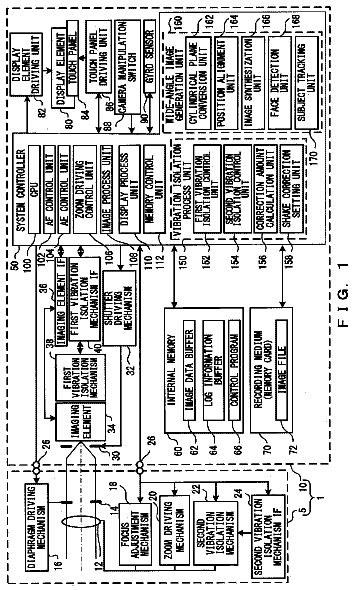
FIG. 1 is a block diagram illustrating examples of functional configurations of an image capturing apparatus according to a first embodiment of the present invention, at a time of moving image shooting;
FIGS. 2A to 2C are diagrams illustrating operations of a first RS distortion correction amount calculation unit and a second RS distortion correction amount calculation unit according to the embodiment;
FIGS. 3A to 3D are diagrams illustrating operations of the second RS distortion correction amount calculation unit and a residual RS distortion correction amount calculation unit according to the embodiment;
FIGS. 4A to 4D are diagrams illustrating rolling shutter distortion correction by an RS distortion correction unit according to the embodiment;
FIG. 5 is a block diagram illustrating examples of functional configurations, of the image capturing apparatus according to the embodiment, for generating a still image from a moving image;
FIGS. 6A to 6D are diagrams illustrating correction of residual RS distortion amounts by the RS distortion correction unit according to the embodiment;
FIG. 7 is a block diagram illustrating examples of functional configurations, of an image capturing apparatus according to a second embodiment, for moving image shooting;
FIGS. 8A and 8B are diagrams illustrating processing of a movement detection/calculation unit according to the second embodiment;
FIGS. 9A to 9D are diagrams illustrating processing of the movement detection/calculation unit and a residual RS distortion correction control unit according to the second embodiment;
FIG. 10 is a flowchart illustrating processing of the residual RS distortion correction control unit according to the second embodiment; and
FIGS. 11A to 11C are graphs for illustrating processing of step S 102 of FIG. 10 .
Description of the embodiments
Exemplary embodiments of the present invention will be described in detail in accordance with the accompanying drawings. First Embodiment
Moving Image Shooting
FIG. 1 is a block diagram illustrating functional configurations of a video camera serving as an example of an image capturing apparatus 100 according to a first embodiment of the present invention, at a time of moving image shooting. Hereinafter, the functional configurations of the image capturing apparatus 100 of FIG. 1 and examples of their operations will specifically be described.
An image capturing optical system 101 for ƒms a subject image (not shown) on an image sensor 102 . Note that although FIG. 1 shows the image capturing optical system 101 constituted by a single lens, the image capturing optical system 101 commonly includes a plurality of lenses such as a zoom lens and a focus lens, a diaphragm, and the like so as to be able to control zooming, focusing, an amount of incident light, and the like. The image sensor 102 of the present embodiment is a CMOS image sensor that includes a plurality of photoelectric conversion elements arranged two-dimensionally, and sequentially outputs accumulated electric charges at a different timing for each line in a frame period, from the upper section to the lower section of the image sensor 102 . As described above, this driving method is referred to as a rolling shutter method, and hereinafter, “RS” refers to an abbreviation of “rolling shutter”. The image sensor 102 converts, using the rolling shutter method, the subject image formed by the image capturing optical system 101 into electrical signals serving as image signals, and supplies the converted electrical signals to a signal processing unit 103 . The signal processing unit 103 generates video signals complying with, for example, an NTSC format from the image signals obtained by the image sensor 102 , and supplies the generated video signals to an image memory 104 .
An angular velocity sensor 111 detects a shake of the image capturing apparatus 100 as an angular velocity signal, and supplies the angular velocity signal to an A/D converter 112 . The A/D converter 112 digitalizes the angular velocity signal from the angular velocity sensor 111 , and supplies the digitalized signal as angular velocity data to a first RS distortion correction amount calculation unit 113 and a second RS distortion correction amount calculation unit 114 provided inside a microcomputer (μCOM) 110 .
An RS distortion correction unit 105 corrects a rolling shutter distortion generated in a captured image stored in the image memory 104 based on a calculation result of the second RS distortion correction amount calculation unit 114 . The residual RS distortion correction amount calculation unit 115 calculates a residual rolling shutter distortion correction amount based on calculation results of the first RS distortion correction amount calculation unit 113 and the second RS distortion correction amount calculation unit 114 , and supplies the calculated residual correction amount to a metadata generation unit 116 .
A moving image encoding unit 107 compresses the video signals supplied from the RS distortion correction unit 105 into a predetermined format, and supplies the compressed video signals to the metadata generation unit 116 . The metadata generation unit 116 generates metadata based on the data supplied from the residual RS distortion correction amount calculation unit 115 , and records, in a recording medium 108 , the generated metadata in association with moving image data that is output from the moving image encoding unit 107 . Note that the metadata handled in the metadata generation unit 116 will be described in detail later.
The recording medium 108 may be, for example, a magnetic recording medium such as a hard disk, or an information recording medium such as a semiconductor memory, but is not limited to these. Furthermore, a display device 106 is constituted by, for example, a liquid crystal display element (LCD) or the like, and displays an image that is output from the RS distortion correction unit 105 .
The following will specifically describe the operations of the RS distortion correction unit 105 , the first RS distortion correction amount calculation unit 113 , the second RS distortion correction amount calculation unit 114 , the residual RS distortion correction amount calculation unit 115 , and the metadata generation unit 116 according to the first embodiment.
FIGS. 2A to 2C are diagrams illustrating operations of the first RS distortion correction amount calculation unit 113 . FIG. 2A shows a captured image in which arbitrary image lines are denoted by L 0 to L 6 . FIG. 2B is a graph for which an ordinate indicates the time and an abscissa indicates the temporal change in the camera shake amount or camera shake angle on an image sensing surface, the camera shake amount or camera shake angle being calculated based on the angular velocity data. Note that charge accumulation timings of the image lines L 0 to L 6 of the captured image of FIG. 2A respectively correspond to times T 0 to T 6 . The graph of FIG. 2B shows the camera shake amount or camera shake angle gradually changing from the time T 0 to the time T 6 .
The first RS distortion correction amount calculation unit 113 calculates camera shake amounts or camera shake angles a 0 to a 6 on the image sensing surface at the respective times T 0 to T 6 based on outputs of the A/D converter 112 , and stores the calculated camera shake amounts or camera shake angles in a memory (not shown) provided inside the μCOM 110 . Note here that the first RS distortion correction amount calculation unit 113 is described as being a unit for calculating seven pieces of data of the camera shake angles a 0 to a 6 , but the number of pieces of data to be acquired is not limited to this. The number of pieces of data to be calculated is arbitrary as long as a plurality of pieces of camera shake angle data are calculated in synchronization with the charge accumulation timings of image lines of an image.
The first RS distortion correction amount calculation unit 113 further performs calculation for subtracting the camera shake angle a 3 at the time T 3 that corresponds to the charge accumulation timing of the image line L 3 that extends in the image center of the captured image, from the camera shake angles a 0 to a 6 . FIG. 2C is a graph illustrating the results of this calculation, and its ordinate and abscissa are the same as those of FIG. 2B . Assuming that shifted camera shake angles b 0 to b 6 are results obtained by subtracting the camera shake angle a 3 from the camera shake angles a 0 to a 6 , the calculation results are such that the camera shake angles a 0 to a 6 are shifted so that b 3 =0 is satisfied, as shown in FIG. 2C . The first RS distortion correction amount calculation unit 113 supplies the shifted camera shake angles b 0 to b 6 to the second RS distortion correction amount calculation unit 114 and the residual RS distortion correction amount calculation unit 115 .
The second RS distortion correction amount calculation unit 114 uses the shifted camera shake angles b 0 to b 6 to perform calculation of data (RS distortion correction setting data) that is to be set in the RS distortion correction unit 105 . Specifically, the second RS distortion correction amount calculation unit 114 determines whether or not the shifted camera shake angles b 0 to b 6 exceed a correction limit within which a rolling shutter distortion can be corrected using the method that will be described later, and if the shifted camera shake angles do not exceed the correction limit, the shifted camera shake angles b 0 to b 6 are set as the RS distortion correction setting data in the RS distortion correction unit 105 . If the shifted camera shake angles b 0 to b 6 exceed the correction limit, the shifted camera shake angles b 0 to b 6 are corrected so that the RS distortion correction setting data falls within the correction limit. For example, in FIG. 2C , the RS distortion correction amounts that correspond to the shifted camera shake angles b 1 and b 5 are the correction limits, the shifted camera shake angles b 0 to b 6 are multiplied by a gain so that the maximum value of the shifted camera shake angles b 0 to b 6 falls within a range of the RS distortion correction amounts that correspond to the shifted camera shake angles b 1 to b 5 .
FIG. 3A is a graph for which an ordinate indicates the same as that of FIG. 2B , and an abscissa indicates the RS distortion correction amount. Note that the units of the abscissas of FIG. 3A and FIG. 2C are the same. The solid line graph of FIG. 3A shows adjusted correction amounts c 0 to c 6 , which are products obtained by multiplying the shifted camera shake angles b 0 to b 6 by a gain, and the dashed line graph shows the same graph as that of FIG. 2C . The second RS distortion correction amount calculation unit 114 sets the adjusted correction amounts c 0 to c 6 as the RS distortion correction setting data in the RS distortion correction unit 105 .
FIGS. 4A to 4D are diagrams illustrating methods in which the RS distortion correction unit 105 performs rolling shutter distortion correction based on the RS distortion correction setting data c 0 to c 6 calculated by the second RS distortion correction amount calculation unit 114 . FIG. 4A shows correction of a rolling shutter distortion in the lateral direction of the image, FIG. 4B shows correction of a rolling shutter distortion in the longitudinal direction of the image, and FIG. 4C shows correction of a rolling shutter distortion in the rotating direction of the image. FIG. 4D shows the concept of an output image when the rolling shutter distortions of FIGS. 4A, 4B, and 4C are completely corrected.
The rectangle of FIG. 4A shows the range of an image 401 constituted by all pixels that can be obtained from the image sensor 102 . A small parallelogram inside the image 401 indicates a subject 402 that was originally square-shaped and is captured while being distorted at an angle by a rolling shutter distortion caused by a shake of the image capturing apparatus 100 in the yaw direction. The graph on the right side of FIG. 4A is a graph for which an ordinate indicates the time and an abscissa indicates the correction amount of the rolling shutter distortion (RS distortion correction amount), and in which the pieces of RS distortion correction setting data at the times T 0 to T 6 are plotted.
The RS distortion correction unit 105 calculates, using a well-known method such as linear interpolation, polynomial approximation, or least squares, the RS distortion correction amounts that correspond to all the image lines of the captured image, based on the discrete RS distortion correction setting data at the times T 0 to T 6 . The RS distortion correction unit 105 corrects the rolling shutter distortion by changing the image output start position in the horizontal direction every image line according to the RS distortion correction amounts. That is, by restricting an image readout range 403 as the large parallelogram of FIG. 4A , the rolling shutter distortion is corrected.
Furthermore, in FIG. 4B , the small and vertically long rectangle inside the image 401 indicates the subject 402 that was originally square-shaped and is distorted so as to extend vertically by a rolling shutter distortion caused by a shake of the image capturing apparatus 100 in the pitch direction. The graph on the right side of FIG. 4B is a graph for which an ordinate indicates the time and an abscissa indicates the RS distortion correction amount, and in which the pieces of RS distortion correction setting data at the times T 0 to T 6 are plotted.
As described above, the RS distortion correction unit 105 calculates the RS distortion correction amounts at the charge accumulation timings for all the image lines of the captured image, based on the discrete RS distortion correction setting data at the times T 0 to T 6 . The RS distortion correction unit 105 corrects the rolling shutter distortion by shifting and changing the image readout lines up and down according to the RS distortion correction amounts. That is, by restricting the image readout range 403 as the rectangle immediately inside the range of the captured image of FIG. 4B , the rolling shutter distortion is corrected. Note that in FIG. 4B , the sections with the dotted lines show image readout ranges when the rolling shutter distortion is not corrected.
Similarly, in FIG. 4C , the small sector inside the image 401 indicates the subject 402 that was originally square-shaped and is captured while being distorted in the shape of a sector by a rolling shutter distortion caused by a shake of the image capturing apparatus 100 in the direction of rotation about the optical axis. The graph on the right side of FIG. 4C is a graph in which an ordinate indicates the time and an abscissa indicates the RS distortion correction amount, and in which the pieces of RS distortion correction setting data at the times T 0 to T 6 are plotted.
As described above, the RS distortion correction unit 105 calculates the RS distortion correction amounts at the charge accumulation timings corresponding to all the image lines of the captured image, based on the discrete RS distortion correction setting data at the times T 0 to T 6 . The RS distortion correction unit 105 corrects the rolling shutter distortion by changing the image readout positions so as to rotate the image readout lines about the image center O serving as the original point according to the RS distortion correction amounts. That is, by restricting the image readout range 403 as the large sector-shaped figure of FIG. 4C , the rolling shutter distortion is corrected.
FIG. 4D shows, as described above, the output image that is obtained when the rolling shutter distortion is completely corrected without any distortion remaining uncorrected, and the subject that is distorted in FIGS. 4A to 4C is corrected to the original shape. The correction that gives a result as shown in FIG. 4D is performed when the data in the second RS distortion correction amount calculation unit 114 that was supplied from the first RS distortion correction amount calculation unit 113 does not exceed a correction limit, and is set without change as the RS distortion correction setting data in the RS distortion correction unit 105 . On the other hand, when the data in the second RS distortion correction amount calculation unit 114 that was supplied from the first RS distortion correction amount calculation unit 113 exceeds the correction limit, the distortions of the subjects of FIGS. 4A to 4C approximate the state of FIG. 4D , but are not completely corrected.
The residual RS distortion correction amount calculation unit 115 calculates this residual rolling shutter distortion correction amount (residual RS distortion amount), and supplies the calculated residual rolling shutter distortion correction amount to the metadata generation unit 116 . The following will describe calculation in the residual RS distortion correction amount calculation unit 115 with reference to FIGS. 3A and 3B . The residual RS distortion correction amount calculation unit 115 calculates differences between the camera shake amounts or shifted camera shake angles b 0 to b 6 (the dashed line of FIG. 3A ) on the image sensing surface that are calculated by the first RS distortion correction amount calculation unit 113 , and the RS distortion correction setting data c 0 to c 6 (the solid line of FIG. 3A ) that are calculated by the second RS distortion correction amount calculation unit 114 , at the respective times T 0 to T 6 .
FIG. 3B is a graph showing the calculation results obtained by the calculation of bn−cn (n=0 to 6) with respect to the data at the respective times T 0 to T 6 . Here, the calculation is given as the residual RS distortion amount dn=bn−cn (n=0 to 6).
As described with reference to FIGS. 4A to 4D , the range of an output image subjected to the rolling shutter distortion correction is smaller than the captured image. Therefore, it is necessary to convert the data on the residual RS distortion amount into data that corresponds to the output image range. In FIG. 3C , the solid line rectangle indicates the captured image 401 , and the solid line rectangle inside the captured image 401 indicates the output image 403 . FIG. 3D is a graph for which an ordinate indicates the time and an abscissa indicates the residual RS distortion amount, as with in FIG. 3B . The residual RS distortion amount needs to be data that is associated with an output image. Therefore, as shown in FIG. 3C , the image lines on which data on the residual RS distortion amounts are recorded are set as L 10 to L 16 in the range of the output image 403 . Then, the times that correspond to the charge accumulation timings of the image lines L 10 to L 16 are defined as T 10 to T 16 , and the adjusted residual RS distortion amounts e 0 to e 6 at the times T 10 to T 16 are calculated, as shown in the graph of FIG. 3D . The calculation of the adjusted residual RS distortion amounts e 0 to e 6 is performed using a method such as linear interpolation or polynomial approximation interpolation, by adjusting the residual RS distortion amounts at the times T 10 to T 16 based on T 0 to T 6 and the residual distortion amounts d 0 to d 6 of the graph of FIG. 3B .
The residual RS distortion correction amount calculation unit 115 supplies the residual RS distortion amounts e 0 to e 6 to the metadata generation unit 116 . The metadata generation unit 116 records, in the recording medium 108 , the residual RS distortion amounts e 0 to e 6 in association with an image for each frame (frame image) that includes the residual RS distortion amount, as metadata. By repeatedly performing the above-described processing for a plurality of frames, a moving image is recorded.
Still Image Generation
The following will describe processing in which a user determines, from a moving image, a frame image that is used for generating a still image. FIG. 5 is a block diagram illustrating functional configurations, of a video camera that serves as an example of the image capturing apparatus 100 according to the first embodiment, for generating a still image from moving image data. Hereinafter, the functional configurations and examples of their operations will be described with reference to FIG. 5 . Note that in FIG. 5 , the same reference numerals are given to the functional configurations used in common with the case of moving image shooting described with reference to FIG. 1 , and detailed descriptions thereof are omitted.
An operation member 210 is a member for a user to perform various types of operations, the operation member 210 being a touch panel, an arrow key, various types of buttons, or the like, for example. A UI control unit 211 provided inside the μCOM 110 performs processing for analyzing an operation of the operation member 210 by the user, and transmitting an instruction to an appropriate configuration block of the image capturing apparatus 100 .
When the user operates the operation member 210 to designate a given frame (designated frame) of a shot moving image and the UI control unit 211 detects the operation for generating a still image, the UI control unit 211 transmits, to a moving image decoding unit 201 , an instruction to decode the frame image of the designated frame. Furthermore, the UI control unit 211 transmits, to a metadata analyzing unit 212 , an instruction to read out the metadata that is recorded in the recording medium 108 in association with the designated frame.
The moving image decoding unit 201 decodes the compressed moving image recorded in the recording medium 108 to generate a frame image of the designated frame, and stores the generated frame image in the image memory 104 . The metadata analyzing unit 212 analyzes the metadata of the designated frame to determine whether or not a residual RS distortion amount is included. If a residual RS distortion amount is not included, the metadata analyzing unit 212 transmits an instruction not to perform rolling shutter distortion correction to the RS distortion correction unit 105 , whereas if a residual RS distortion amount is included, the metadata analyzing unit 212 sets the residual RS distortion amount in the RS distortion correction unit 105 .
The RS distortion correction unit 105 performs correction of the residual RS distortion amount in accordance with the instruction of the metadata analyzing unit 212 . The metadata analyzing unit 212 analyzes the metadata of the designated frame, determines the image size of the still image, and sets the determined image size in an image size correction unit 202 .
The image size correction unit 202 changes the image size in accordance with the instruction of the metadata analyzing unit 212 . A still image encoding unit 203 encodes, using JPEG compression, the still image of the image size changed by the image size correction unit 202 , and the eventual encoded still image data is recorded in the recording medium 108 .
The following will describe in detail the operations of the correction of a residual RS distortion amount, by the metadata analyzing unit 212 , the RS distortion correction unit 105 , and the image size correction unit 202 . As described above, when, in FIG. 1 , data supplied from the first RS distortion correction amount calculation unit 113 to the second RS distortion correction amount calculation unit 114 exceeds the correction limit, the RS distortion correction unit 105 does not completely correct the rolling shutter distortion at a time of moving image shooting. Accordingly, a moving image in which the distortion of the subject remains is recorded in the recording medium 108 . The operation when the image of the designated frame selected by the user includes the residual RS distortion amounts shown in the graph of FIG. 3D will be described with reference to FIGS. 6A to 6D .
FIGS. 6A to 6D are diagrams illustrating, based on the data indicating the residual RS distortion amounts set by the metadata analyzing unit 212 , the methods in which the RS distortion correction unit 105 performs correction of the residual RS distortion amounts. FIG. 6A shows correction in the lateral direction of the image, FIG. 6B shows correction in the vertical direction of the image, and FIG. 6C shows correction in the rotational direction of the image. FIG. 6D shows the image in which the residual RS distortion amounts of FIGS. 6A, 6B, and 6C are corrected.
The thin solid line rectangle in the figure on the left side of FIG. 6A indicates the range of a recorded image 601 recorded in the recording medium 108 . The small parallelogram inside the recorded image 601 indicates a subject 602 that was originally square-shaped and is distorted at an angle by a rolling shutter distortion in the lateral direction, showing the state in which the rolling shutter distortion at a time of shooting is not completely corrected. The graph on the right side of FIG. 6A is a graph for which an ordinate indicates the time and an abscissa indicates the residual RS distortion amount, and in which the set data for the residual RS distortion amounts at the times T 10 to T 16 are plotted.
The RS distortion correction unit 105 performs correction of the residual RS distortion amounts by changing the image output start position in the horizontal direction every image line according to the residual RS distortion amounts. That is, by restricting an image readout range 603 as the large parallelogram with a thick line of FIG. 6A , the correction of the residual RS distortion amounts is realized.
Furthermore, in FIG. 6B , the small and vertically long rectangle inside the recorded image 601 also indicates the subject 602 . Here, the subject 602 was originally square-shaped and is distorted so as to extend vertically by a rolling shutter distortion in the vertical direction, showing the state in which the rolling shutter distortion at a time of shooting is not completely corrected. The graph on the right side of FIG. 6B is a graph for which an ordinate indicates the time and an abscissa indicates the residual RS distortion amount, and in which the set data for the residual RS distortion amounts at the times T 10 to T 16 are plotted.
The RS distortion correction unit 105 performs correction of the residual RS distortion amounts by shifting and changing the image readout lines up and down according to the residual RS distortion amounts. That is, by restricting the image readout range 603 as the thick line parallelogram of FIG. 6B , the correction of the residual RS distortion amounts is realized.
Similarly, in FIG. 6C , the small sector inside the recorded image 601 also indicates the subject 602 . Here, the subject 602 was originally square-shaped and is distorted in the shape of a sector by a rolling shutter distortion in the rotational direction of the image, showing the state in which the rolling shutter distortion at a time of shooting is not completely corrected. The graph on the right side of FIG. 6C is a graph an for which ordinate indicates the time and an abscissa indicates the residual RS distortion amount, and in which the set data for the residual RS distortion amounts at the times T 10 to T 16 are plotted.
The description continues in the full USPTO document.
 Lapsed, fee not paid18 drawings