 Lapsed, fee not paid3 drawings
Vehicles & Drones · US 9,738,306 B2
Energy absorbing steering column assembly
A steering column assembly for a vehicle includes a housing defining a bore that extends along an axis.
US 9,738,308 B2 · Assignee: TOYOTA JIDOSHA KABUSHIKI KAISHA · Inventors: Ueyama; Masao et al.
Sheet 1 of 9 from the published document. All sheets in the USPTO PDF
A control device ( 50 ) for an electric power steering device ( 10 ) is configured to: store a basic target return speed (Vrb), which increases in magnitude as the magnitude of a steering angle (θ) increases; calculate, when a steering wheel ( 14 ) is being returned to a neutral position, the basic target return speed (Vrb) based on an actual steering angle (Step 10 ); calculate a transitional target return speed (Vtrt), which gradually increases in magnitude and gradually approaches the basic target return speed as the magnitude of the actual steering wheel decreases; and control, when the magnitude of a difference between the basic target return speed and the transitional target return speed is more than a reference value, a steering assist torque so that a return speed reaches the transitional target return speed (Step 20 to Step 160 ).
In an electric power steering device, there is known such control of a return speed that, when a steering wheel is brought into a state of returning toward a neutral position, the steering wheel appropriately returns toward the neutral position even when the self-aligning torque of the steered wheels is low. In this return speed control, a basic target return speed, which is an ideal return speed, is calculated based on a vehicle speed and a steering angle, and a steering assist torque is controlled through feedback control based on a deviation between an actual return speed and the basic target return speed so that the actual return speed reaches the basic target return speed. The basic target return speed is calculated so as to increase in the magnitude as the magnitude of the steering angle increases. At the beginning of the return speed control, the magnitude of the deviation between
1 of 9 drawing sheets so far from the published document, cropped to the drawing. Every sheet is in the USPTO PDF.
What the patent claimed, word for word. All of it is now free to use.
The present invention relates to an electric power steering device to be used for vehicles such as motor vehicles.
In an electric power steering device, there is known such control of a return speed that, when a steering wheel is brought into a state of returning toward a neutral position, the steering wheel appropriately returns toward the neutral position even when the self-aligning torque of the steered wheels is low. In this return speed control, a basic target return speed, which is an ideal return speed, is calculated based on a vehicle speed and a steering angle, and a steering assist torque is controlled through feedback control based on a deviation between an actual return speed and the basic target return speed so that the actual return speed reaches the basic target return speed.
The basic target return speed is calculated so as to increase in the magnitude as the magnitude of the steering angle increases. At the beginning of the return speed control, the magnitude of the deviation between the actual return speed and the basic target return speed is large. Thus, the magnitude of a feedback control amount is significantly large, and hunting is often caused in which a state of an excessive actual return speed and a state of an insufficient actual return speed with respect to the basic target return speed are alternately repeated. In order to avoid unnecessary increase/decrease in the return speed due to the hunting, for example, as disclosed in Japanese Patent Application Laid-open No. Sho 62-241768, such a configuration that as the magnitude of the deviation of the return speed increases, a gain of the feedback control is decreased is known.
In the electric power steering device disclosed in Japanese Patent Application Laid-open No. Sho 62-241768, at the beginning of the return speed control, the magnitude of the deviation of the return speed is large. Thus, the gain of the feedback control is decreased, and the magnitude of the feedback control amount does not increase to a large value. Therefore, the magnitude of the actual return speed does not become sufficiently large, and thus a decrease speed of the magnitude of the steering angle is small. Thus, the change in the basic target return speed with respect to the elapsed time is slow, and a state in which the magnitude of the deviation of the return speed is large continues for a long period. Therefore, a state in which the gain of the feedback control is set to a small value also continues for a long period. As a result, the period until the steering wheel returns to the neutral position becomes significantly long. Thus, with the electric power steering device disclosed in Japanese Patent Application Laid-open No. Sho 62-241768, the unnecessary increase/decrease in the return speed due to the hunting can be avoided, but the original purpose of the return speed control, which is to appropriately return the steering wheel toward the neutral position, cannot be attained.
It is a primary object of the present invention to change, in the return speed control for the electric power steering device, the return speed in synchronization with the basic target return speed as closely as possible and appropriately return the steering wheel toward the neutral position while avoiding the unnecessary increase/decrease in the return speed due to the hunting.
According to one embodiment of the present invention, there is provided an electric power steering device, including: a steering assist torque applying device; and a control device configured to control a steering assist torque to be applied by the steering assist torque applying device to a steering apparatus for a vehicle, in which: the control device includes a storage device configured to store a relationship between a basic target return speed, which increases in magnitude as a magnitude of an actual steering angle increases, and a steering angle, and is configured to calculate, when a steering wheel is being returned toward a neutral position, the basic target return speed based on the actual steering angle and the relationship, and to apply feedback control to the steering assist torque so that a return speed of the steering wheel reaches the calculated basic target return speed.
The control device is configured to calculate, when the steering wheel is being returned toward the neutral position, a transitional target return speed, which gradually increases in magnitude and gradually approaches the basic target return speed as the magnitude of the actual steering angle decreases, and to apply, when a magnitude of a difference between the basic target return speed and the transitional target return speed is more than a reference value, feedback control to the steering assist torque so that the return speed of the steering wheel reaches the transitional target return speed in place of the calculated basic target return speed.
With the above-mentioned configuration, when the steering wheel is being returned toward the neutral position, the transitional target return speed, which gradually increases in magnitude and approaches the basic target return speed as the magnitude of the actual steering angle decreases, is calculated. At the beginning of the return speed control, the magnitude of the difference between the basic target return speed and the transitional target return speed is more than the reference value, and the feedback control is applied to the steering assist torque so that the return speed of the steering wheel reaches the transitional target return speed.
The transitional target return speed is calculated so as to gradually approach the basic target return speed as the magnitude of the actual steering wheel decreases, and thus the magnitude of the transitional target return speed gradually increases as the return speed control progresses. The actual return speed of the steering wheel is controlled so as to reach the transitional target return speed, and thus the magnitude of the actual return speed gradually increases as the return speed control progresses. Thus, the magnitude of the difference between the actual return speed and the transitional target return speed does not increase, and the magnitude of the feedback control amount does not thus excessively increase.
Thus, the unnecessary increase/decrease in the return speed due to the hunting caused by the rapid increase in the return speed of the steering wheel can be avoided. Moreover, the gain of the feedback control does not need to be decreased, and the excessive extension of the period until the steering wheel returns to the neutral position as in the electric power steering device disclosed in Japanese Patent Application Laid-open No. Sho 62-241768 can also be avoided.
Moreover, when the transitional target return speed gradually approaches the basic target return speed, and the magnitude of the difference between the basic target return speed and the transitional target return speed becomes equal to or less than the reference value, the return speed of the steering wheel is controlled so as to reach the basic target return speed. Thus, the return speed of the steering wheel is controlled to reach the transitional target return speed, which gradually approaches the basic target return speed, and then, to reach the basic target return speed, which is the original target value. Thus, the return speed can be changed in synchronization with the basic target return speed as closely as possible while avoiding the unnecessary increase/decrease in the return speed due to the hunting, thereby appropriately returning the steering wheel toward the neutral position.
Expressions such as “the steering wheel is returned toward the neutral position” and “returns the steering wheel toward the neutral position” herein are not limited to the case in which the target position is the neutral position in the return speed control. In other words, the expressions include, in a case in which the steering wheel is incrementally turned beyond the neutral position toward the opposite direction such as in reciprocating steering, a return of the steering wheel toward the neutral position. Further, the expressions include a case in which the return of the steering wheel is finished before the steering wheel reaches the neutral position such as a case in which when the steering wheel is being returned toward the neutral position, the steering wheel is held or incrementally steered toward the direction opposite to the neutral position.
According to one embodiment of the present invention, the control device is configured to determine whether or not the steering wheel is being returned toward the neutral position by an active return steering by a driver, and to calculate, in a case in which the steering wheel is being returned toward the neutral position by the active return steering by the driver, the transitional target return speed so that the magnitude of the transitional target return speed increases compared with a case in which the steering wheel is being returned toward the neutral position not by the active return steering by the driver.
In general, when the steering wheel is being returned toward the neutral position by the active return steering by the driver, the driver is considered to desire an efficient return of the steering wheel toward the neutral position. Conversely, when the steering wheel is being returned toward the neutral position not by the active return steering by the driver, the driver is considered to desire a moderate return of the steering wheel toward the neutral position.
With the above-mentioned configuration, it is determined whether or not the steering wheel is being returned toward the neutral position by the active return steering by the driver. Further, in the case in which the steering wheel is being returned toward the neutral position by the active return steering by the driver, the transitional target return speed is calculated so that the magnitude increases compared with the case in which the steering wheel is being returned toward the neutral position not by the active return steering by the driver.
Thus, while the steering wheel is being returned toward the neutral position by the active return steering by the driver, the magnitude of the transitional target return speed increases. Thus, the steering wheel can efficiently be returned toward the neutral position by increasing the magnitude of the steering assist torque. In contrast, while the steering wheel is being returned toward the neutral position not by the active return steering by the driver, the magnitude of the transitional target return speed does not increase. Thus, the steering wheel can moderately be returned toward the neutral position by preventing the magnitude of the steering assist torque from being excessively increased.
The determination of whether or not the steering wheel is being returned toward the neutral position by the active return steering by the driver may be made in an arbitrary manner. For example, in International Patent WO2014-087546A filed by the applicant of the subject application, there is described determining which of an active operation, a passive operation, and a holding operation, the driver is carrying out as the steering operation based on a sum of a product of a steering angular velocity and the steering torque, and a product of the steering angle and the derivative of the steering torque.
The “active operation” is an operation in which energy of steering is provided from the driver to a steering apparatus, namely, an operation in which the driver actively carries out the transitional steering, thereby increasing energy of the steering held by the steering apparatus. The “passive operation” is an operation in which energy of steering is provided from the steering apparatus to the driver, namely, an operation in which the energy of the steering held by the steering apparatus is transmitted to the driver, and the driver passively carries out the transitional steering. The “holding operation” is a state in which the energy of the steering is not given/received between the steering apparatus and the driver, namely, a state in which the driver does not carry out the transitional steering, and the potential energy held by the steering apparatus is not changed.
As disclosed in International Patent WO2014-087546A, a steering power based on a product of the steering angular velocity and the steering torque reflects strength of an intention of the driver to change a travel direction of the vehicle under the state in which the driver carries out the transitional steering operation. On the other hand, a steering power based on a product of the steering angle and the derivative of the steering torque reflects strength of an intention of the driver to permit a rotation of the steering wheel rotated by an inverse input from a road surface. Thus, under the state in which the steering wheel is being returned toward the neutral position, when the steering operation is determined to be the active operation based on the sum of the products, the steering wheel may be determined to be being returned toward the neutral position by the active return steering by the driver.
According to another embodiment of the present invention, the control device is configured to: set, at predetermined periods, the calculated basic target return speed to a preliminary target return speed; set, when a magnitude of a difference between the preliminary target return speed and a previous target return speed is more than an increase restriction value, a current target return speed so that a magnitude of the current target return speed is a sum of a magnitude of the previous target return speed and the increase restriction value; set, when the magnitude of the difference between the preliminary target return speed and the previous target return speed is not more than the increase restriction value, the current target return speed to the preliminary target return speed; and apply low-pass filtering to the current target return speed to calculate the transitional target return speed.
With the above-mentioned configuration, the calculated basic target return speed is set to the preliminary target return speed at predetermined periods. When the magnitude of the difference between the preliminary target return speed and the previous target return speed is more than the increase restriction value, the current target return speed is set so that the magnitude of the current target return speed is the sum of the magnitude of the previous target return speed and the increase restriction value. When the magnitude of the difference between the preliminary target return speed and the previous target return speed is not more than the increase restriction value, the current target return speed is set to the preliminary target return speed. Further, the transitional target return speed is calculated by applying the low-pass filtering to the current target return speed.
Thus, by restricting the increase amount of the target return speed at predetermined periods to be equal to or less than the increase restriction value, the increase rate of the magnitude of the transitional target return speed can be prevented from being excessive. Further, the transitional target return speed is calculated by applying the low-pass filtering to the target return speed, and thus, the transitional target return speed can reliably and gradually be caused to approach the basic target return speed.
Further, according to another embodiment of the present invention, the control device is configured to determine whether or not the steering wheel is being returned toward the neutral position by an active return steering by a driver, and to increase, in a case in which the steering wheel is being returned toward the neutral position by the active return steering by the driver, a cutoff frequency for carrying out the low-pass filtering compared with a case in which the steering wheel is being returned toward the neutral position not by the active return steering by the driver.
With the above-mentioned configuration, it is determined whether or not the steering wheel is being returned toward the neutral position by the active return steering by the driver. Further, in the case in which the steering wheel is being returned toward the neutral position by the active return steering by the driver, the cutoff frequency for the low-pass processing is increased compared with the case in which the steering wheel is being returned toward the neutral position not by the active return steering by the driver.
Thus, when the steering wheel is being returned toward the neutral position by the active return steering by the driver, the cutoff frequency increases. Thus, the steering wheel can efficiently be returned toward the neutral position by increasing the magnitude and the increase rate of the transitional target return speed. In contrast, when the steering wheel is being returned toward the neutral position not by the active return steering by the driver, the cutoff frequency does not increase. Thus, the steering wheel can moderately be returned toward the neutral position by preventing the magnitude and the increase rate of the transitional target return speed from being excessive.
Further, according to another embodiment of the present invention, the control device is configured to increase, in a case in which the magnitude of the actual steering angle is small, the increase restriction value compared with a case in which the magnitude of the actual steering angle is large.
With the above-mentioned configuration, under the state in which the magnitude of the actual steering angle is small, and the self-aligning torque of the steered wheels is low, the steering wheel can efficiently be retuned toward the neutral position by increasing the increase restriction value to further increase the magnitude and the increase rate of the transitional target return speed. In contrast, under the state in which the magnitude of the actual steering angle is large, and the self-aligning torque of the steered wheels is high, the unnecessary increase/decrease in the return speed due to the hunting can be avoided by decreasing the increase restriction value to further decrease such a fear that the magnitude and the increase rate of the transitional target return speed excessively increase.
Further, according to another embodiment of the present invention, the control device is configured to determine whether or not the steering wheel is being returned toward the neutral position by an active return steering by a driver, and to increase, in a case in which the steering wheel is being returned toward the neutral position by an active return steering by a driver, the increase restriction value compared with a case in which the steering wheel is being returned toward the neutral position not by the active return steering by the driver.
With the above-mentioned configuration, it is determined whether or not the steering wheel is being returned toward the neutral position by the active return steering by the driver. Further, in the case in which the steering wheel is being returned toward the neutral position by the active return steering by the driver, the increase restriction value is increased compared with the case in which the steering wheel is being returned toward the neutral position not by the active return steering by the driver.
Thus, when the steering wheel is being returned toward the neutral position by the active return steering by the driver, the increase restriction value increases. Thus, the steering wheel can efficiently be returned toward the neutral position by increasing the magnitude and the increase rate of the transitional target return speed. In contrast, when the steering wheel is being returned toward the neutral position not by the active return steering by the driver, the increase restriction value does not increase. Thus, the steering wheel can moderately be returned toward the neutral position by preventing the magnitude and the increase rate of the transitional target return speed from being excessive.
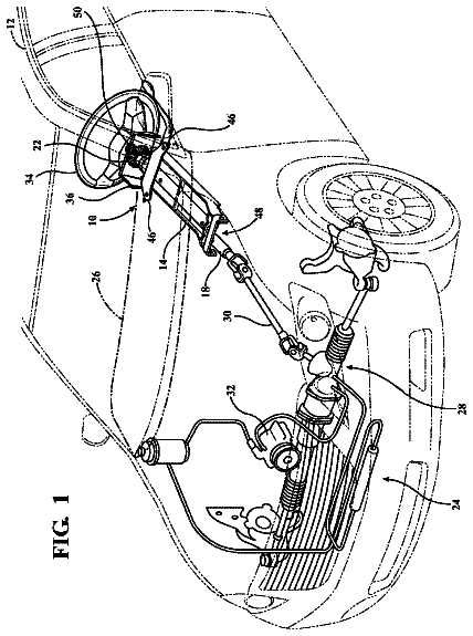
FIG. 1 is an explanatory diagram for illustrating an overview of an electric power steering device according to a first embodiment of the present invention.
FIG. 2 is a flowchart for illustrating a control routine for a return speed Vr toward a neutral position of a steering wheel according to the first embodiment.
FIG. 3 is a flowchart for illustrating a calculation routine for a cutoff frequency fcl and an increase change restriction value ΔVrc to be executed in Step 40 of FIG. 2 .
FIG. 4 is a flowchart for illustrating a control routine for the return speed Vr toward the neutral position of the steering wheel in an electric power steering device according to a second embodiment of the present invention.
FIG. 5 is a flowchart for illustrating a calculation routine for the cutoff frequency fcl and the increase change restriction value ΔVrc to be executed in Step 40 of FIG. 4 .
FIG. 6 is a graph for showing a map to be used to calculate a basic target return speed Vrb based on the absolute value of a steering angle θ and a vehicle speed V.
FIG. 7 is a graph for showing a map to be used to calculate a correction coefficient Ks based on the absolute value of the steering angle θ.
FIG. 8 is a graph for showing a map to be used to calculate the increase change restriction value ΔVrc based on the absolute value of the steering angle θ.
FIG. 9 is a graph for showing a relationship between the steering angle θ and a steering angular velocity θd for an example of a steering operation in which, in a vehicle in which the return speed Vr is not controlled, the steering wheel is incrementally steered from the neutral position, undergoes a hold steering state, and is returned toward the neutral position.
FIG. 10 is a graph for showing changes in the steering angle θ (top row) and the steering angular velocity θd (bottom row) for the example in which the steering wheel is incrementally steered from the neutral position, undergoes the hold steering state, and is returned toward the neutral position.
FIG. 11 is a graph for showing an example of changes in the steering angle θ (top row), the target return speed (middle row), and a steering assist torque (bottom row) for showing a comparison in actions and effects of the first embodiment with the electric power steering device disclosed in Japanese Patent Application Laid-open No. Sho 62-241768.
FIG. 12 is a graph for showing a difference in an increase rate of the magnitude of a transitional target return speed Vtrt depending on whether or not a steering operation of a driver is a passive steering operation according to the first embodiment.
FIG. 13 is a graph for showing a difference in an increase rate of the magnitude of the transitional target return speed Vtrt depending on whether or not the steering operation of the driver is a passive steering operation according to the second embodiment.
Now, with reference to the accompanying drawings, preferred embodiments of the present invention are described in detail. First Embodiment
FIG. 1 is an explanatory diagram for illustrating an overview of an electric power steering device 10 according to a first embodiment of the present invention. The electric power steering device 10 according to this embodiment is constructed as a column assist type electric power steering device. The electric power steering device according to the present invention may be a power steering device of another type such as a rack assist type electric power steering device with its motor coaxial with a rack as long as a steering assist torque can be controlled.
In FIG. 1 , the electric power steering device 10 is applied to a steering apparatus 12 . The steering apparatus 12 includes a steering wheel 14 to be operated by a driver, an upper steering shaft 16 configured to rotate along with the steering wheel 14 , an intermediate shaft 18 , and a steering mechanism 20 . The intermediate shaft 18 is coupled to a bottom end of the upper steering shaft 16 at a top end of the intermediate shaft 18 via a universal joint 22 , and is coupled to a pinion shaft 26 of the steering mechanism 20 at a bottom end of the intermediate shaft 18 via a universal joint 24 .
The steering mechanism 20 includes a rack-and-pinion apparatus 28 , and tie rods 30 L and 30 R. The rack-and-pinion apparatus 28 converts a rotation of the pinion shaft 26 into a translational motion in a vehicle lateral direction of a rack bar 32 , and also performs conversion in an opposite direction. The tie rods 30 L and 30 R are pivotally connected to tips of the rack bar 32 at inner ends of the tie rods 30 L and 30 R. The tie rods 30 L and 30 R are pivotally connected, at outer ends of the tie rods 30 L and 30 R, to knuckle arms 36 L and 36 R provided to carriers (not shown) for front left and right wheels 34 L and 34 R.
Thus, the rotational displacement and the rotational torque of the steering wheel 14 are converted by the steering mechanism 20 into pivot displacement and pivot torques about kingpin axes (not shown) of the front wheels 34 L and 34 R, and then are transmitted to the front wheels 34 L and 34 R. Moreover, pivot displacement and pivot torques about the kingpin axes received by the front left and right wheels 34 L and 34 R from a road surface 38 are transmitted by the steering mechanism 20 to the steering wheel 14 as a rotational displacement and a rotational torque, respectively.
The electric power steering device 10 includes a power steering unit 46 including a motor 42 and a conversion device 44 . The conversion device 44 includes a worm gear fixed to a rotation shaft of the motor 42 , and a worm wheel fixed to the upper steering shaft 16 , which are not shown in FIG. 1 . A rotational torque of the motor 42 is converted into a rotational torque of the upper steering shaft 16 by the conversion device 44 , and is transmitted to the upper steering shaft 16 as the steering assist torque. Thus, the power steering unit 46 is configured to function as a steering assist torque applying device for applying the steering assist torque to the steering apparatus 12 .
Moreover, the electric power steering device 10 includes an electronic control device 50 . The electronic control device 50 functions as a control device configured to control a steering assist torque by controlling the rotational torque applied by the motor 42 as described in detail later. Signals representing a steering angle θ and a steering torque T are input to the electronic control device 50 respectively from a steering angle sensor 52 and a torque sensor 54 provided to the upper steering shaft 16 . Moreover, a signal representing a vehicle speed V is also input to the electronic control device 50 from a vehicle speed sensor 56 . Note that, the steering angle sensor 52 and the torque sensor 54 respectively detect the steering angle θ and the steering torque T, which are defined to be positive when the vehicle is steered toward a right turn direction.
The electronic control device 50 includes a microcomputer 66 including a CPU 58 , a ROM 60 , a RAM 62 , and an input/output port device connected to one another via a bidirectional common bus 64 . The ROM 60 is configured to function as a storage device configured to store a program for carrying out control for the steering assist torque to be executed in accordance with flowcharts illustrated in FIG. 2 and FIG. 3 described later, maps shown in FIG. 6 to FIG. 8 , and the like. The CPU 58 and the RAM 62 are configured to function as a calculation device configured to carry out various calculations for controlling the steering assist torque as detailed later.
In particular, FIG. 6 is a graph for showing a relationship between the steering angle θ, the vehicle speed V, and a basic target return speed Vrb for a range in which the steering angle θ is equal to or more than 0. A curve representing the basic target return speed Vrb for a range in which the steering angle θ is negative, which is not shown in FIG. 6 , is point symmetric to the curve of FIG. 6 with respect to the origin. The basic target return speed Vrb is an ideal return speed when the steering wheel 14 is returned from a position at which the magnitude of the steering angle θ is infinite toward the neutral position, and is determined by specifications of the vehicle. The basic target return speed Vrb is in general a function of the square root of the absolute value of the steering angle θ, and the magnitude of the basic target return speed Vrb increases as the absolute value of the steering angle θ increases, and decreases as the vehicle speed V increases. The return speed such as the basic target return speed Vrb is a rotational angular velocity when the steering wheel 14 returns toward the neutral position.
The electronic control device 50 is configured to, when the steering wheel 14 is being incrementally steered or is being held, control the steering assist torque for the incremental steering or the hold steering. In other words, the electronic control device 50 is configured to calculate a target steering assist torque Tat based on the steering torque T and the vehicle speed V. Further, the electronic control device 50 is configured to control the power steering unit 46 so that a steering assist torque Ta reaches the target steering assist torque Tat, thereby decreasing a steering load imposed on the driver.
In contrast, the electronic control device 50 is configured to, under a state in which the steering wheel 14 is being returned toward the neutral position, follow the flowcharts illustrated in FIG. 2 and FIG. 3 to control a return speed Vr of the steering wheel 14 toward the neutral position. In other words, the electronic control device 50 is configured to calculate the basic target return speed Vrb based on the steering angle θ and the vehicle speed V, and calculate a target return speed Vrt for appropriately returning the steering wheel 14 toward the neutral position based on the basic target return speed Vrb. Further, the electronic control device 50 is configured to control the steering assist torque Ta by controlling the power steering unit 46 through feedback control based on the deviation between the actual return speed Vr of the steering wheel 14 and the target return speed Vrt so that the actual return speed Vr reaches the target return speed Vrt.
Referring to the flowcharts illustrated in FIG. 2 and FIG. 3 , a description is now given of the control of the return speed Vr of the steering wheel 14 toward the neutral position (hereinafter simply referred to as “control” as necessary) according to the first embodiment. The control in accordance with the flowchart illustrated in FIG. 2 is repeated at predetermined periods under the state in which the steering wheel 14 is being returned toward the neutral position. In the course of the control in accordance with the flowchart illustrated in FIG. 2 , when the steering wheel 14 is brought into the incremental steering state or the hold steering state, the control of the steering assist torque transitions to the control of the steering assist torque for the incremental steering or the hold steering.
The determination of whether or not the steering wheel 14 is being returned toward the neutral position is not a part of the present invention, and may be made in any manner. For example, the above-mentioned determination may be made based on any one of or a combination of whether or not the magnitude of the steering torque T is less than a value required for the hold steering, whether or not the signs of the steering angle θ and the steering angular velocity θd are different from each other, whether or not the signs of the steering angle θ and the steering torque T are different from each other, and whether or not the signs of the steering torque T and the steering angular velocity θd are different from each other.
First, in Step 10 , through use of the map shown in FIG. 6 , the basic target return speed Vrb corresponding to the steering angle θ and the vehicle speed V is calculated. In this case, the basic target return speed Vrb is calculated to be a negative value when the steering angle θ has a positive value, and is calculated to be a positive value when the steering angle θ has a negative value.
In Step 20 , it is determined whether or not a flag F is 1, that is, whether or not calculation of a transitional target return speed Vtrt described later is unnecessary and a final target return speed Vfrt is to be set to the basic target return speed Vrb. When an affirmative determination is made, the control proceeds to Step 150 . When a negative determination is made, in Step 30 , a preliminary target return speed Vprt is set to the basic target return speed Vrb, and then, the control proceeds to Step 40 . The flag F is reset to 0 when the control starts, and is also reset to 0 when the steering wheel 14 is brought into the incremental steering state or the hold steering state in the course of the control in accordance with the flowchart illustrated in FIG. 2 .
In Step 40 , in accordance with the flowchart illustrated in FIG. 3 , a cutoff frequency fcl for low-pass filtering in Step 110 described later, and further, an increase change restriction value ΔVrc for restricting the increase amount of the target return speed Vrt are calculated. The calculation of the cutoff frequency fcl and the increase change restriction value ΔVrc carried out in accordance with the flowchart illustrated in FIG. 3 is described later.
In Step 80 , it is determined whether or not the absolute value of a deviation ΔVprt between the preliminary target return speed Vprt and a previous target return speed Vrtf is more than the increase change restriction value ΔVrc, that is, whether or not the restriction on the increase amount of the target return speed Vrt is necessary. When a negative determination is made, in Step 90 , the target return speed Vrt is set to the preliminary target return speed Vprt. In contrast, when an affirmative determination is made, in Step 100 , the target return speed Vrt is set to a sum Vrtf+signθ.Math.ΔVrc of the previous return speed Vrtf and a product signθ.Math.ΔVrc of signθ and the increase change restriction value ΔVrc, where signθ represents the sign of the steering angle θ.
In Step 110 , through application of the low-pass filtering to the target return speed Vrt at the cutoff frequency fcl set in Step 40 , the transitional target return speed Vtrt is calculated.
In Step 120 , it is determined whether or not the absolute value of a deviation ΔVtrt between the basic target return speed Vrb and the transitional target return speed Vtrt is more than a reference value α (positive constant). In other words, it is determined whether or not the return speed control cannot be caused to transition to the control based on the basic target return speed Vrb, and thus the control based on the transitional target return speed Vtrt needs to be continued. When a negative determination is made, in Step 130 , the flag F is set to 1, and then, the control proceeds to Step 150 . In contrast, when an affirmative determination is made, in Step 140 , both of the final target return speed Vfrt and the previous target return speed Vrtf to be used in the next control cycle are set to the transitional target return speed Vtrt, and then, the control proceeds to Step 160 .
In Step 150 , the return speed control may transition from the control based on the transitional target return speed Vtrt to the control based on the basic target return speed Vrb, and thus the final target return speed Vfrt is set to the basic target return speed Vrb.
In Step 160 , the actual return speed Vr is calculated as a time derivative of the steering angle θ, and, based on a deviation between the final target return speed Vfrt and the actual return speed Vr, feedback control is applied to the steering assist torque Ta (assist torque in the return direction) so that the deviation decreases.
Referring to the flowchart illustrated in FIG. 3 , a description is now given of the calculations of the cutoff frequency fcl and the increase change restriction value ΔVrc to be carried out in Step 40 .
First in Step 44 , a time derivative Td of the steering torque T is calculated, and in accordance with Expression (1), an active/passive index value INs is calculated. When INs has a positive value, the steering operation by the driver is an active steering operation, and the driver is actively returning the steering wheel 14 toward the neutral position. When INs is a negative value, the steering operation by the driver is a passive steering operation, and the arms of the driver are moved by the rotation of the steering wheel 14 returning toward the neutral position. When INs is 0, the steering operation of the driver is neither the active steering operation nor the passive steering operation, and a state in which the steering wheel 14 is not rotated is present. INs=θd.Math.T+θ.Math.Td
In Step 46 , it is determined whether or not the active/passive index value INs of the steering is a negative value, that is, whether or not the steering operation by the driver is the passive steering operation. When a negative determination is made, the control proceeds to Step 56 , and when an affirmative determination is made, the control proceeds to Step 48 .
In Step 48 , based on the absolute value of the steering angle θ, a correction coefficient Ks (positive value) based on the magnitude of the steering angle θ is calculated from the map shown in FIG. 7 . As shown in FIG. 7 , the correction coefficient Ks is calculated so as to generally decrease as the absolute value of the steering angle θ increases, to be less than 1 in a region where the absolute value of the steering angle θ is large, and to be more than 1 in a region where the absolute value of the steering angle θ is small.
In Step 50 , in accordance with Expression (2), the cutoff frequency fcl for the low-pass filtering in Step 110 is calculated. In this expression, fclb is a base value (positive constant) for the cutoff frequency. The active/passive index value INs for the steering is negative, and 1+INs is thus less than 1. Thus, fclb.Math.(1+INs) is less than the base value fclb. fcl=fclb .Math.(1 +INs ).Math. Ks
In Step 52 , based on the absolute value of the steering angle θ, the increase change restriction value ΔVrc (positive value) is calculated from the map shown in FIG. 8 . As shown in FIG. 8 , the increase change restriction value ΔVrc is calculated so as to generally decrease as the absolute value of the steering angle θ increases.
In Step 56 , it is determined whether or not the active/passive index value INs of the steering is a positive value, that is, whether or not the steering operation by the driver is the active steering operation. When a negative determination is made, the control proceeds to Step 64 , and when an affirmative determination is made, the control proceeds to Step 58 . Note that, in Step 56 , a negative determination is made when the active/passive index value INs of the steering is 0. The active/passive index value INs is calculated in accordance with Expression (1). Thus, even when it is determined that the steering wheel 14 is being returned toward the neutral position, the active/passive index value INs may be 0.
The description continues in the full USPTO document.
About 6,728 words. The USPTO PDF has it with every drawing.
Fees are due 3.5, 7.5 and 11.5 years after grant. This patent expired on August 22, 2025, so the fee marked "not paid" was the one that went unpaid.
ELECTRIC POWER STEERING DEVICE
Filed May 2016 · published Dec 2016Electric power steering device
Filed May 2016 · granted Aug 2017Earlier publications, parents and continuations. None of them can still be enforced, or this patent would not be listed.
Prior art cited by the examiner or applicant. Useful when you check your own idea for novelty.
Everything on this page comes from the documents linked above.


