 Lapsed, fee not paid9 drawings
Industrial Equipment · US 9,732,549 B2
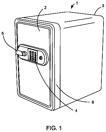
Safe with concealed hinge
A safe with a concealed hinge assembly.
US 9,732,561 B2 · Assignee: Carter, Jr.; Ernest E. · Inventors: Carter, Jr.; Ernest E.
Sheet 1 of 23 from the published document. All sheets in the USPTO PDF
This patent application discloses method and apparatus to cut an extended slot connecting a well to a substantial cross section of a desired producing formation whereby material can flow freely between the formation and the wellbore and at least partially overcome the flow limitations of low permeability formations without the environmental issues associated with hydraulic fracturing. It is further disclosed that the connection between said slot and the formation may be further enhanced by explosive or combustive processes that rapidly generate gas pressure within the large surface area of the slot, thereby changing its characteristics and forcing open additional fractures into the cross section of formation exposed to the slot. The method may significantly increase the recoverable percentage or natural gas from low permeability deposits such as shale and coal.
A well is typically drilled in order to extract resources from the earth or as a zone to dispose of unwanted materials. The resources may include oil and gas, minerals, or even geothermal heat and things to be disposed may include waste heat, contaminated water, or even carbon dioxide. In many cases the effective production of resources from a well is limited by the permeability of the subterranean formation strata and the total surface area of the well bore and nearby fractures. The value of oil and gas wells varies greatly according to the rate at which the well produces. Some formations such as shale rock have been found to contain large volumes of natural gas but the permeability of the rock is so low that wells drilled into the shale rock produce only small flows of gas which are insufficient to pay for the expense of the well. To obtain greater recovery of gas, wells are often dril
1 of 23 drawing sheets so far from the published document, cropped to the drawing. Every sheet is in the USPTO PDF.
What the patent claimed, word for word. All of it is now free to use.
A well is typically drilled in order to extract resources from the earth or as a zone to dispose of unwanted materials. The resources may include oil and gas, minerals, or even geothermal heat and things to be disposed may include waste heat, contaminated water, or even carbon dioxide. In many cases the effective production of resources from a well is limited by the permeability of the subterranean formation strata and the total surface area of the well bore and nearby fractures.
The value of oil and gas wells varies greatly according to the rate at which the well produces. Some formations such as shale rock have been found to contain large volumes of natural gas but the permeability of the rock is so low that wells drilled into the shale rock produce only small flows of gas which are insufficient to pay for the expense of the well. To obtain greater recovery of gas, wells are often drilled so that they turn horizontally and run for some distance within a thin shale layer to increase the area of well bore within the layer.
The surface area of the well can be further increased by injecting water into specific areas at high pressure to crack the rock in a process known as hydraulic fracturing. Hydraulic fracturing is the most common technique for increasing the productive surface area of a well. Hydraulic fracturing is not always as effective as desired due to the difficulty of controlling the orientation, thickness, and magnitude of the fractures. Injecting very large volumes of chemically treated water is also an environmental concern as it can potentially pollute fresh water or cause earth tremors. Fractures may also breech and damage natural impermeable barriers underground allowing water to intrude into new areas. In the case of a shale gas well, intruding water can interrupt the production of gas.
The present patent application describes a method and apparatus for increasing well productivity without hydro-fracturing. The method describes a method and apparatus for manipulating an abrasive cutting member within a well to cut an extended slot. This extended slot connects the well to a substantial cross sectional area of a desired producing formation whereby the rate of flow of resources between the formation and the well is substantially increased. The effective increase in surface area may provide results comparable to hydraulic fracturing while avoiding the environmental issues associated with that technology. The method and apparatus described herein provide means of enhancing a well by mechanical cutting of a very extensive planar groove, herein referred to as a slot, cut, gallery, or panel, along a well bore and extending away from the well bore axis and cutting across a very large cross section of the formation.
In this patent application a “slot” generally comprises a deep longitudinal groove extending away from a bore hole for a distance of at least several feet but potentially hundreds of feet. The slot is nominally a planar cut beginning along an extended length of the well bore and extending a substantial distance away from the wellbore through the subterranean rock formation. The slot effectively increases the available surface area of the well bore to enhance the flow connection between the formation and the well bore.
The slot may be thinner than the diameter of the well bore but is much thicker and more uniform than a man-made hydraulic fracture and preferably may extend a hundred feet or more into the formation all along a substantial length of the well bore connecting it to a substantial cross sectional area of the desired producing formation. The “desired producing formation” may contain oil, natural gas, soluble mineral resources, geothermal heat, Kerogen (oil shale) or any resource. The slot acts as a gathering gallery that contacts a very large surface area potentially crossing many existing fractures in the formation. Many of these natural fractures also expose a large surface area of the formation. This increases the potential flow rate between the formation and the well bore much like freeways increase the mobility of cars within a city. The slot can also facilitate flow of material from the well into the formation. This could be used to inject carbon dioxide into a formation at lower pressure so that it remains in a well-defined area. In this case the resource is a disposal zone. The slot can also be used as a down hole heat exchanger to harvest geothermal heat.
The slot may be cut by any suitable process that can cut an extended opening deep into the formation from an initial drilled borehole. In this patent application, the inventor teaches that a slot may be created to improve productivity of a well intended to extract hydrocarbon, geothermal, or chemical resources from the earth or to inject materials into the earth for environmental remediation. Additionally the method includes means for further improving the connection between a slot and a formation by causing a rapid increase in gaseous pressure within the slot to open cracks in the rock formation.
Generating the force to cut a slot from the well bore deep into the formation is a previously unsolved problem which is solved by the method herein with various types of apparatus disclosed herein. It is desirable to cut a slot which is deep enough and long enough to increase the effective surface area of the wellbore by at least a factor of 10 and perhaps a factor of 1000 or more. This magnitude of improvement requires of slot along a substantial length of the well bore of hundreds or thousands of feet that is preferably cut to depths of tens to hundreds of feet. The slot must be of sufficient width or conductivity that it does not restrict the flow of the resource being sought.
In prior art, U.S. Pat. No. 4,346,761 jets of high pressure water have been used to cut through well casing as well as cutting into the formation. However the jet energy is reduced by ambient hydrostatic pressure and also diminishes rapidly away from the jet orifice, especially in a liquid environment, effectively limiting the depth of a slot to less than a meter. Jet nozzles on the end of a flexible hose have been shown to be capable of carving out cavities around a well bore as in U.S. Pat. No. 3,958,641 but are unsuitable for cutting deep slots because they cut randomly in all directions and not just in a planar path.
Explosive shaped charges are used to cut perforations into the well bore to expose more surface area; however these are usually less than a meter deep and are typically a series of small holes and not a continuous slot. Under-reaming tools have mechanisms that expand down hole and enlarge the well bore itself but are limited to doubling or tripling the bore diameter. Mechanical tools that drag along the bore hole or have rotating end mill style cutters can cut a shallow groove but generally cannot form cuts deeper than the diameter of the well bore and none in prior art can cut a slot deeper than twice the diameter of the wellbore. In conventional drilling, the force to drill through rock comes largely from the tremendous weight of the pipe on the drill bit combined with rotation of the drill bit. Generating the required mechanical force to cut rock deep in a slot away from a relatively small borehole becomes increasingly difficult as the cut deepens.
In prior art, U.S. Pat. No. 4,442,896 it has been disclosed that a “U” shaped bore hole looping down into the ground and back to the surface could have a wire rope cable extending through it and back to the surface with pulling means on each end to reciprocate the cable and cut upward from the “U” shaped borehole in a coal bed. Tension on the cable from both surface locations produces an upward cutting force. This approach would form a cut that is very tall vertically compared to its horizontal length and may be less desirable to access a thin gas production formation.
It is uncertain if this upward cutting from a “U” shaped bore hole has ever been accomplished from a vertical borehole. Drilling a “U” shaped hole down and back to the surface is difficult and making two independently drilled holes connect to form a “U” is also difficult. Reciprocating the cable would require two surface equipment rig locations and coordination between them or a pulley system back to the first rig. Another problem is that for holes that traverse nearly 180 degrees of arc, the friction may be so great that the cable becomes stuck. Placing pulley sheaves down hole on the ends of pipes can reduce friction but the required pulley diameter is generally too large to place in the common size of hole.
More recently USPTO Patent Application 20070158072 describes a similar process wherein two bore holes are drilled from the surface and then turned laterally to intersect. Then a flexible linear cutting device such as a diamond wire saw is circulated from the surface and fished through the intersection and back to the surface. It is claimed to cut a planar fissure that begins at the intersection and extends some distance along the wellbores. This method is also thought to have feasibility issues related to friction of the wire saw around too great of a total arc of contact, nearly 180 degrees at the intersection plus the total arc of curvature of both wells. Since friction increases exponentially with the contact angle the cable would be likely to be stuck by friction alone.
Chainsaw mechanisms and circulation cable saws circulate a continuous chain or wire rope abrasive cable as a cutting element and are commonly used as hand tools for cutting objects. These solve the friction problem by having the chain or cable run on a wheel or low friction pulley so that the cutting member contacts the surface to be cut only along a smaller arc of contact. These have been considered for cutting a slot in a wellbore but they are limited by the minimum diameter of the wheel supporting and driving the cutting elements of the cable or chain. An abrasive cable cutting a 1 inch wide slot might require a pulley wheel 2 feet in diameter and so the hole would have to be that large as well. The ratio of the bore diameter to the width and depth of the cut that is mechanically feasible is believed insufficient for increasing the productivity of wells. Delivering a sufficient amount of energy to the device to cut at a reasonable rate is also problematic. This type of mechanism cutting more than two or three times the borehole diameter into the wall of the hole for a substantial length is probably not possible.
During drilling of wells the reduced diameter body of a drill pipe can become pressed against the wall of the hole at a bend or angle change and if the wall of the hole is soft the moving pipe may accidently cut a slot into the wall. This slot is known as a keyseat and is highly undesirable since the larger diameter drill pipe joints and drill bit cannot be pulled back up through this keyseat. Keyseat wipers are used in the drill pipe so that these keyseats can be regularly reamed out so that the drill pipe does not get stuck. U.S. Pat. No. 2,904,313, U.S. Pat. No. 3,420,323 and U.S. Pat. No. 4,330,043 are examples of such keyseat wipers.
Keyseats occur only at the point where there is a sharp bend in the line of the borehole. The resulting keyseat will have a substantially triangular or crescent profile shape. While many efforts have been made to prevent the cutting of a keyseat or to recover from one, no prior art has contemplated the potential benefit of intentionally cutting a keyseat. In the present method, some of the basic physical principles that cause the keyseat problem while drilling a well can be utilized to provide the force against the side of the hole to cut an extended longitudinal slot of relatively uniform depth and increase the total productive surface area of the wellbore significantly as shown in FIG. 43 and FIG. 44 .
Keyseats slightly increase the total surface area of a wellbore but generally since they occur only at sudden bends in the borehole any such increase would not be significant even if they cut deeply into the bend. Such accidental surface area increase would certainly not amount to even double the original surface area of a wellbore through the entire production zone. The present method intentionally makes substantially uniform slots along a substantial length of a wellbore to increase the total surface area of the wellbore within the producing formation. This would typically increase surface area by at least a factor of three.
In the present method the shape profile curvature of the hole may be designed to allow a suitable abrasive element means to bear against the wall of a borehole with a substantially uniform force as it moves along an extended curved length of the borehole. Thus instead of forming a slot only at a local bend point in the borehole, an extended slot is formed along a substantial length of the borehole.
Prior art also includes the use of explosives and propellants in boreholes to fracture a formation. Russian Patents numbers 2154733 and 2178073 describe pumping a fuel and oxidizer solution into a well and igniting it to generate multiple fractures from the wellbore. U.S. Pat. No. 5,346,015 describes injection of gaseous fuel such as propane and a gaseous oxidizer into a well and igniting it to produce a rubble zone to enhance production. Generally explosions have been found to produce local rubble and dust rather than deep penetrating fractures.
The method and apparatus described herein is sufficiently unlike prior art that there is no agreed standard terminology for describing all components and there are many possible synonyms. The terms borehole, wellbore, well bore, hole, well, and open hole may be used interchangeably to refer to the hole that is drilled down into the earth to extract resources. The earth that the hole passes through may be called the formation rock strata, the formation, the rock, hot rock, the shale, the earth, the “face of the cut”, or simply the sidewall of the hole.
The “slot” refers to the cavity perpendicular to the wellbore that is formed by the method and apparatus. It may also be referred to as “the cut”, groove, crevasse, planar slot, panel, gallery, or pathway. The slot may be in any orientation even if nominally referred to as “the vertical cut”. A slot is a longitudinal groove along at least a portion of a wellbore wherein groove is at least deeper than 2 well bore diameters away from the wall of the wellbore. In this patent application a slot is not just a few inches or even a few feet deep but is intended to be tens or hundreds of feet deep all along a length of thousands of feet along the wellbore. The wellbore is directionally drilled with a profile and curvature that maximizes the cross section of the producing formation cut by the slot. A slot is preferably oriented such that it cuts through a desired producing formation in the way most likely to cross existing fractures and exposes a substantial cross section of the producing formation to the well bore. By “substantial cross section” we mean at least over 10,000 square feet and preferably on the order of 100,000 square feet. Slots of less than this magnitude would not achieve the aim of increasing productivity of a well.
Aspects of the invention deal with pipe in a directionally drilled wellbore which can curve through a substantial arc of curvature so and even curve back toward the surface at its distal end. The terms “down” and “up”, “below” and “above”, “upper” and “lower”, “bottom” and “top”, when applied to the wellbore or tools in the wellbore or the slot are to be understood as a reference to direction along the path of the wellbore and not as references to absolute elevation or true vertical depth. Likewise the term reciprocation is to be understood as moving up and down when referring to the drill pipe in a vertical drill rig and back and forth along the stroke of a slant hole or horizontal drilling rig and also along a curved or directionally drilled well bore or a slot.
The term “drilling fluid” may refer to any fluid circulated in the hole including drilling mud, air, steam, water, foam, water with additives, salt water, calcium chloride water, potassium chloride water, polymers, bentonite dispersed in water, or oil based mud made from hydrocarbons and various types of clay.
The term “pipe” comprises most any type of oil well tubular good including drill pipe, oil well tubing, casing, drill collars, and coil tubing. The pipe may be referred to as “the drill pipe”, or “the string”. The pipe can also be a cutting element or a tensile element and be referred to in general terms as an abrasive cutting member. Pipe may be made of steel or from carbon fiber or fiber glass fiber composite material. The “pipe” may be the same drill pipe, casing or tubing used to drill the well or it may be a different one with special characteristics, such as a sand screen or external flush threaded connections.
Steel wire rope is a rope made from steel wires which may optionally have a core made of other material. Wire rope may also be referred to as cable, wire rope cable, steel wire rope cable, diamond wire, diamond abrasive cable, wire saw, cutting cable, cable saw, or wire rope saw. It may also be described in general terms as: abrasive tensile member, connected tensioned abrasive member, or abrasive cutting member. In this patent application it may also mean wire rope that has been coated or infused with rubber or plastic material, or which has abrasive materials or abrasive beads added to it as in commercial diamond wire saw material. The abrasive material may be impregnated in sleeves, called beads, which fit over the wire rope and are separated by coil springs.
When a cable is used to cut the slot it is attached to a shoe tool which could also be called a nose tool to secure it to the bottom of the drill pipe.
The apparatus comprising a pipe and a connected tensioned abrasive cutting member may also be called a Slot Drill, wire rope saw or a Slot Drilling String.
In creating pulses of gas pressure to open fractures from a slot the terms combustion, combustive, explosion, explosive, deflagration, rapid burning and similar terms related to chemical reactions that rapidly release gas are used as interchangeable terms. Thus a claim of using combustion of a mixture of natural gas to increase pressure and cause fractures in a slot also applies if the pressure wave or shock wave of the reaction is technically an explosion. Likewise an explosive substance placed in the slot is intended to create a very fast spike of pressure against the planar surface and not to break it into small chunks so it could be considered a deflagration.
FIG. 1 shows a drilling rig 1 , with a borehole 2 , extending down to a subterranean gas producing formation layer 3 , and extending horizontally through said formation for a significant distance. A pipe 4 , in the well bore extends to the end of the wellbore. A wire rope cable 5 , is attached at the surface to an automatic tensioning winch 6 , and the other end is attached to the bottom end of the pipe 7 . The pipe is reciprocated through the available stroke 8 , of the rig. As the pipe is reciprocated the wire rope cable also reciprocates and makes a planar cut 9 , through the formation.
In FIG. 2 the horizontal run of the pipe 4 , in the hole is extended and turns 45 degrees upward or to one side at the end. This geometry change allows the cable 5 , to cut a much larger area 10 , as it is reciprocated through the same stroke 8 . A second horizontal lateral hole 11 , branches off to form a shallow arcing curve along the formation instead of traveling on a true horizontal path. In this hole the wire rope cable cuts a more uniform depth 12 , along the hole.
In FIG. 3 the end of the pipe has a special shoe 13 , or “shoe” piece where the end of the cable 5 , is attached by some suitable means. The cable tension tends to force the shoe against the side of the hole, to help prevent rotation. If the pipe rotates, the cable tension would have to increase so this tends to prevent rotation. The shoe may have a milled flat 14 , that also helps it resist rotation. Rotation of the milled flat would cause the centerline of the pipe to move further away from the wall of the hole and cable tension is keeping the pipe pressed against the wall of the hole.
In FIG. 4 , which is a section view, the milled flat has the same radius 15 , as the hole.
In FIG. 5 , an alternate design section view, the milled flat comprises one or more roller wheels 16 , within the body of the shoe to reduce friction and rotational forces.
In FIG. 6 , a shoe 17 , or shoe piece is shown that combines a releasable cable attachment means 18 , with a circulating port 19 , and a low friction swivel 20 . A cementing plug 21 , is pumped down the pipe and lands on piston 22 temporarily closing the circulating port and moving piston to shear pins and extrude grease from cavity 23 causing shell piece 24 to separate from conical mandrel 25 and release end of cable 5 .
FIG. 7 , longitudinal section view II, shows the box end conical sleeve 26 , with the groove 27 , for the cable and the external hole for the cable to reach the groove.
FIG. 8 radial cross section III-III shows the cable 5 , being clamped between the conical sleeve 26 , and the conical mandrel 28 .
FIG. 9 section V-V shows the exterior of the conical sleeve with the hole for the cable 29 , and the flat 30 .
FIG. 10 section Iv-Iv shows the radial cross section of the shoe or shoe piece with the milled flat ground to the radius of the hole 31 .
FIG. 11 shows a well with three laterals that branch off from one horizontal lateral. Each of the three laterals is cut separately and transitions from a vertical cut near the main bore 32 , to a near horizontal cut at the ends 33 .
FIG. 12 shows a partially horizontal cut made using a down hole grab tool 34 , to hold tension at a point below the initial right angle bend so that a greater total arc of contact may be cut within the thin production formation layer. The end of the hole turns up so that the cut will angle upward rather than being horizontal.
FIG. 13 shows a pinwheel type pattern 37 , which could be developed with multiple kickoffs of laterals cut as in FIG. 12 .
FIG. 14 shows a down hole cable tensioning tool. The tool grips the cable 5 , below it and responds to internal pipe pressure by extending a hydraulic sleeve 38 , upward that stretches the cable.
FIG. 15 shows a radial section view of the cable grip tool. The hinged cover 39 , clamps over two die halves 40 , that clamp the cable, by means of pressure applied from a rubber sleeve 41 , on the inside diameter of the tool.
FIG. 16 shows a cross section of the cable grip mechanism. The two die halve 40 rest in a tapering cavity that brings them closer together around the cable when they are pulled down against the spring 42 , by the release of cable tension from the winch on the surface while the pipe interior is pressurized by circulating fluid under pressure.
FIG. 17 shows the exterior view of the top of the hinged cover 39 with 4 hinge bolts 43 , and six additional bolts 44 , to secure it.
FIG. 18 shows a side exterior view of the grab tool with the cable 5 , threaded through the hinged cover 39 .
FIG. 19 shows the reciprocating pipe tool running in a long horizontal hole within a thin shale formation 45 , and cutting downward to the form a wide slot. The shoe piece 46 , is attached to the cable extending back to the surface, which helps the tool remain properly oriented. The tool tools cutting means comprise jets 47 , rolling cutter wheels 48 , and rock picks 49 .
FIG. 20 shows the reciprocating pipe tool cutter section with the jets 47 , rolling cutter wheels 48 , and rock picks 49 . The tool also includes jam nuts 50 , to rotationally align the tool.
FIG. 21 shows a cross section of the rolling cutter wheels 48 .
FIG. 22 shows the cross section of the jets 47 .
FIG. 23 shows the cable attachment shoe with anchor bolts 51 .
FIG. 24 shows a cross section of the conical picks 49 .
FIG. 25 shows an alternate design for the shoe that uses a gravity reference ball valve 52 , to orient the tool instead of the cable.
FIG. 26 shows a rotating pipe tool with helical ridges 53 , and rock picks 54 .
FIG. 27 shows a cross section of a rotating pipe tool with rock picks in all positions.
FIG. 28 shows a section of drill pipe that has been modified with an auger flight 55 , or helical spring to help transport cuttings from the rotating pipe tool.
FIG. 29 shows the rotating pipe tool 56 , operating in a long horizontal bore hole. As the tool cuts, it drops from its initial position 57 , to progressively lower positions 58 . Cuttings are transported by the auger flights back to the un-enlarged portion of the hole 59 where they are swept out by fluid circulation. The tool is rotated and reciprocated through the stroke of the rig 60 .
FIG. 30 shows the method wherein a drill pipe 61 is attached to an abrasive cable 62 , by means of a tool 63 . The drill pipe is reciprocated by a drill rig 65 through a stroke 65 resulting in a cut slot 66 within the earth formation 67 .
FIG. 31 shows a similar cut through the formation 73 , wherein the cut formed by the stroke 75 of the abrasive cable 69 is at least partially filled with fluid 72 , which is being displaced by compressed gas delivered from the surface 74 , into the drill pipe 68 , through an opening 71 , which becomes open after the opening at the end of the pipe 70 is closed by the action of suitable down hole tools. The fluid may also be displaced by pulling back the tip of the drill pipe 70 to the position 71 .
FIG. 32 shows multiple substantially parallel slots cut in the earth from separate vertical holes. Each slot has at least one pipe 76 and at least one coil tubing 77 connected by a tool 78 inserted into the completed slot to form a engineered geothermal reservoir panel. Fluid flow through the pipe, shown cross section view 79 , carries fluid to multiple coil tubing pipes 81 , that circulate the heated fluid back to the surface. Water flow through fractures 80 , transfer heat from the rock to the slots.
FIG. 33 shows a detailed view of the tool that connects the pipe to the multiple coil tubings. The shoe piece has a ridge shape 82 that helps orients the tool with the slot. The coil tubings 84 are connected by an optional flexible metal bellows hose 83 .
FIG. 34 shows a similar tool adapted for gravel packing the slots. A piston 86 is held in place by a shear pin 87 . Flow through the first coil tubing can distribute sand laden fluid through port 88 . After the pipe is pressurized to shear the shear pin the piston moves to allow fluid to circulate up both pipes in either direction to remove the sand from inside the pipes.
FIG. 35 shows a conventional rotary drilling rig with a special traction winch 93 that is mounted on or around the traveling block 95 so that it moves up and down with the drill pipe through the rigs normal stroke 94 . The spooling winch 91 feeds cable to the gravity take-up mechanism 92 which then feeds cable to the traction winch 93 as needed. The traction winch does not have to move very fast to maintain cable tension so it does not require high horsepower like the winch in FIG. 36 . Below the rig floor 90 the blow out preventer 89 is modified with a slot in its rubber compression element so that it can seal on the cable along side the pipe if required.
At the level of the rig floor 90 , the rotary table slips hold the pipe when new pipe sections are added. The traveling block 95 raises and lowers the drill pipe 96 and the action of the cable 97 cuts a slot shown at 98 in cross section view I-I which collects hydrocarbon or thermal resources from the formation.
FIG. 36 shows a view of similar rig with the drill pipe 99 passing through a special whipstock tool 100 at the bottom of the cemented casing. The whipstock tool allows the drill pipe to kick off in one of 4 directions from a larger diameter vertical cased hole.
FIG. 37 is the section view of the whipstock with 4 laterals coming off the primary vertical well 101 . Each lateral has a slot 102 extending upward as shown in FIG. 36 item 103 .
FIG. 38 shows multiple slots coming off one vertical well bore in different directions from slightly different depths. Each of the slots 104 has primary piping 105 in the original drilled hole 105 and one or more coil tubings 103 at different levels in the slot.
FIG. 39 shows a plan view with 8 laterals 107 coming off a central well bore with fractures in the rock between the laterals.
FIGS. 40 and 41 show a diamond abrasive cable comprising a steel wire rope 108 , and coil springs 109 with a steel sleeve 110 having diamonds 111 embedded into its surface. The sleeve is has a series of angled cuts 113 that allow each radial segment 112 to compress to compress to pass through a smaller diameter.
FIG. 42 shows a U shaped 180 degree turn borehole 114 with piping loops 115 installed to circulate fluid through a vertical slot at depth. A portable rig 119 is positioned over the point where the drill pipe breaks out to the surface. The vertical pipes to the surface are insulated with one pipe 116 inside the other and a vacuum between them. The abrasive cable saw is supported at the surface by pulley sheaves 117 that convey it to a large traction drive wheel 118 that supplies power to circulate the cable through the cut. The traction drive is nominally somewhere in between the two rigs and mounted to a track that slowly moves it along a path perpendicular to a line between the two rigs to maintain cable tension. Alternately each rig could have its own cable reel and traction drive to reciprocate the cable back and forth. When cutting the slot the cable may be moved continuously through the slot by the mechanism at the surface or it may be reciprocated by gripping the cable to smaller tubing pipes 120 which are mechanically reciprocated up and down by the rig.
In FIG. 43 a hole is directionally drilled to form an S-bend that terminates in a substantially downward direction so that the weight of the drill bit and drill pipe 129 add tensile loading to the drill pipe along its length. In FIG. 44 a drill pipe with abrasive cutting surfaces all along its exterior or at located at suitable intervals 127 is placed in the hole 126 and rotated and reciprocated through stroke 124 in the same manner as in FIG. 29 . The abrasive drill pipe cuts into the side of the hole 126 as it seeks a shorter path.
If the hole is in one plane then there is little cutting at the inflection point 130 but if the lower half of the S-bend is at an angle to the top bend then the abrasive action forms a curved ribbon shape slot 125 that extends away from the inflection point 130 . A drag tool 128 on the lower part of the drill pipe can be actuated or inflated to increase the drag and thus the tensile load on the drill pipe so that the cutting force is increased.
The force to cut a slot arises from tensioning an abrasive cutting member along a curved borehole to create force perpendicular to the axis of the abrasive cutting member and borehole. This force causes the abrasive cutting member to bear against the inside radius of the bore hole and cut into the rock as the abrasive cutting member is held in tension and moved along the curving bore hole. Various apparatus may be utilized in conjunction with the pipe movement capabilities of a conventional oil and gas type drilling rig to produce the required tension and movement in the abrasive member. The formation cuttings produced by the action of the abrasive member may be removed from the slot by circulating liquid or foam drilling fluid, gas, or compressed air through the bore hole and the slot.
In this implementation of the method, the abrasive member is a tensioned abrasive cable driven by reciprocation of the drill pipe to perform the cutting. A suitable winch system automatically maintains optimal tension in the cable during reciprocation and also as the drill pipe is lowered to prevent the pipe from twisting and wrapping the cable around the pipe. The slot may be cut from a directionally drilled blind hole from a single rig location using the cable friction and curvature of the hole to produce the lateral cutting force. The energy to cut the rock is all supplied by up and down motion of the drill pipe. Substantially all the cutting action may confined to the open hole below a cased vertical interval by selecting appropriate cable tension and hole curvature parameters.
The apparatus in the first implementation operates somewhat like a down hole hacksaw. The abrasive cutting member is a steel wire rope cable held in tension by a mechanical frame, comprising the drill pipe, which is reciprocated up and down by a drilling rig at the earth's surface such that the cable is also reciprocated along and bears against the inside radius of the of the curved portions of the hole. The portion of the hole where the slot is to be cut is curved rather than straight so that the tensioned cable bears against the inside radius of the curve resulting in abrasive cutting of a slot by the cable.
A winch means or reel of cable on the drilling rig is equipped with suitable controls to hold a desired constant tension on the cable above ground surface. Optionally the cable tensioning mechanism may be attached to the pipe or the traveling block so that it does not have to take in and pay out cable as the pipe moves up and down. The cable tension may also be created by a suitable down hole tool somewhere along the drill pipe. The method of tensioning the cable may be done by any suitable manner such as a down hole tool that tensions the cable without the need to extend the cable back to the surface. This may cost more initially but offers the advantage of not dealing with the cable at the rig floor. The lower end of the cable is connected to the lower end of the drill pipe and the drill pipe is lowered into the hole. The pull of the pipe dropping into the hole pulls down on the cable but the constant tension winch at the surface pays out cable to compensate and maintain a constant cable tension at the surface.
The weight of the cable in the vertical hole decreases local cable tension with depth but the tension at the surface is adjusted to maintain some desired minimum cable tension at the point where the hole begins to curve. Friction of the cable against the inside radius of the hole increases the tension in the cable along the length of the curved hole. Lateral force is generated by the cable tension around the curve of the hole and this force presses the abrasive cable cutting elements into the rock face as the cable is reciprocated. The force perpendicular to the rock face is a function of the radius of curvature and the cable tension at any given point.
Modeling indicates that this first implementation apparatus should be able to cut a 100 foot tall vertical slot upward from the horizontal lateral with a cut length possibly exceeding 2500 feet. This apparatus can operate in a blind hole from a conventional drilling rig and be powered by the drilling rig. Special apparatus to practice the method would include a cable tensioning means and a down hole shoe tool that connects the abrasive cable to the end of the drill pipe. The shoe tool preferably has a mechanism that can release the cable after the slot is cut or if the cable should break. The method utilizes directional drilling services of standard industry skill to drill a hole whose bend radius is closely controlled. The hole may be as straight as possible down to the target formation and then begin a long increasing radius curve through the target formation. The hole may bend in a vertical plane but can also turn in a horizontal plane to create a horizontal cut. The tension on the winch and the bend radius of the hole may be adjusted to produce a substantially uniform cutting force all along the curved portion of the hole, resulting in a uniform cut depth along the curved hole.
The curve profile of the well can be adjusted to generate more cutting in specific portions of the well. A typical well in prior art would be drilled as straight as possible to the desired depth in the target formation and a casing cemented. The hole would then be directionally drilled to curve like a “J” within the producing formation extending as far as possible in the horizontal plane. If applying the method to an existing hole that goes straight down and then turns 90 degrees to go horizontal, then the abrasive cable would produce cutting force only in the bend as in FIG. 1 . FIG. 2 shows a well with two horizontal laterals, one going left and one going right to illustrate two alternate approaches. The one to the right has straight sections with tight curves while the one to the left has a more continuous curve. The one with straight sections will experience initial cutting at only at the curves but will eventually cut an arc between the two bends. However the one on the left side of FIG. 2 with the continuous curve will experience cutting all along the long curve. Cable friction increases along the arc of the curve. If the curve is a constant radius, the cable tension on the down stroke, and thus the cutting depth, will increase along the arc of the curve, at least until it nears the end of the cable. By designing and drilling the hole with an increasing radius curve, it is possible to achieve a substantially uniform depth cut along the curved hole as in FIG. 30 .
After drilling the hole, the drill string is retrieved back to the surface and an abrasive cable is attached to the tip of the drill pipe by a special down hole tool. A winch or on the drill rig, or other tensioning means, is configured to hold a specific tension on the cable as the pipe is lowered back into the hole under its own weight. The cable tension while the pipe is running into the hole prevents the pipe from rotating and wrapping up the cable on the way into the vertical part of the hole. The cable tension also causes the cable to hug the inside radius of the curved hole while the pipe compressive loading tends to make it hug the outside radius of the curve. The friction on the cable around the curve multiplies the initial low cable tension from the winch, increasing exponentially around the curved path. The abrasive cable cuts a pathway on the inside radius curve of the hole, typically upward from the hole, on each downward stroke. The cutting force at any point is a function of local cable tension and radius of curvature so the shape of the cut may be tailored to some extent by drilling the hole with a changing radius of curvature. The cut is nominally upward along a vertical path but can also be made to turn horizontally by curving the hole horizontally.
The cable may also be replaced with other types of abrasive elements such as a pipe with abrasive hard facing or a pipe with a fluted spiral or helical shape like those commonly used as a key seat cutters in oil wells. Such a pipe may optionally include a mechanism to provide rotation to only the abrasive member to obtain more even cutting.
The description continues in the full USPTO document.
About 7,097 words. The USPTO PDF has it with every drawing.
Fees are due 3.5, 7.5 and 11.5 years after grant. This patent expired on August 15, 2025, so the fee marked "not paid" was the one that went unpaid.
Method and Apparatus for Increasing Well Productivity
Filed Dec 2009 · published Oct 2011Method and Apparatus for Increasing Well Productivity
Filed Jun 2016 · published Mar 2017Method and apparatus for increasing well productivity
Filed Jun 2016 · granted Aug 2017Earlier publications, parents and continuations. None of them can still be enforced, or this patent would not be listed.
Prior art cited by the examiner or applicant. Useful when you check your own idea for novelty.
Everything on this page comes from the documents linked above.