Patent Yard Sign in
Lapsed, fee not paidSolo inventor

Safe with concealed hinge

US 9,732,549 B2 · Inventors: Chow; Leslie Ho Leung

USPTO PDF

Overview

Sheet 1 of 9 from the published document. All sheets in the USPTO PDF

Abstract From the patent

A safe with a concealed hinge assembly. A safe body has a pocket with a hinge pin attached to the pocket. A safe door has a hinge lug rigidly attached to the safe door. A hinge assembly is formed when the hinge pin is inserted through the hinge lug allowing for the safe door to be pivotally attached to the safe body. The hinge assembly is contained within the pocket so that the hinge assembly is concealed and protected from tampering. In a preferred embodiment the safe body includes two pockets within a rigidly attached door frame. Two hinge assemblies are contained within the pockets so that they are concealed and protected from tampering.

Why it's free to use

  • The USPTO Official Gazette of October 14, 2025 lists it as expired on August 15, 2025 for an unpaid maintenance fee.
  • It isn't on any reinstatement notice published since.
  • Its 1 US relative has also lapsed, expired or never issued.
  • We check US rights only. Check foreign counterparts before selling abroad.
FiledOctober 12, 2010
GrantedAugust 15, 2017
Expired (fee)August 15, 2025
Application number12/902750
Classification (CPC)E05D7/14 +2 more
Length13 claims · 13 pages

Background From the patent

Safe boxes (also known as “safes”) are well known in the prior art. They are used primarily to protect documents, currency, jewelry, and other valuables from fire and theft. Stand alone safes are very common in homes and businesses throughout the world. A good description of safes is given in U.S. Pat. No. 7,350,470, which is incorporated by reference herein. As stated in the Background section of the ′470 patent, safes typically are constructed of thick metal plates that form an inner compartment for housing the valuables. A door provides access to the inner compartment and a locking mechanism secures the door to the housing to prevent unauthorized entry into the safe interior. The locking mechanism is typically retaining rods that project from the door along inner surfaces into apertures on adjoining surfaces or vice versa. The rods may be maneuvered mechanically, hydraulically, electr

Drawings 9

8 of 9 drawing sheets so far from the published document, cropped to the drawing. Every sheet is in the USPTO PDF.

Figures as described

  • FIG. 1 shows a preferred embodiment of the present invention
  • FIG. 2 shows a preferred door frame
  • FIG. 3 shows a preferred door frame attached to a preferred safe body
  • FIG. 4 shows a preferred safe door
  • FIGS. 5-6 show a top view of a preferred embodiment of the present invention
  • FIGS. 7-11 show the operation of a preferred embodiment of the present invention
  • FIGS. 12-13 show another preferred embodiment of the present invention

Claims 13 total, 2 independent

What the patent claimed, word for word. All of it is now free to use.

  1. 1
    Independent claimA safe having at least one concealed hinge assembly, comprising: A. a safe body, comprising: i. at least one hinge pocket, located within a portion of a wall of the safe body along an inside surface of the wall and having no opening except a single opening, defining a pocket opening, which is completely covered by a surface of the safe door when the safe door is closed, said at least one hinge pocket comprising: a. a horizontal bottom extending inward from the front edge of said safe, b. a vertical back parallel to the front edge of said safe, c. a horizontal top parallel to said horizontal bottom, ii. at least one hinge pin within the hinge pocket and connected to said horizontal bottom, and B. at least one hinge lug rigidly attached to a side wall of the safe door and adapted to extend through said pocket opening and form a hinge assembly when said at least one hinge pin is inserted through said at least one hinge lug in order to pivotally attach the safe door to the safe body; wherein said at least one hinge lug is positioned on the side wall in manner so that when the safe door is closed, the side wall of the safe door completely covers the pocket opening of the at least one hinge pocket so that said at least one hinge assemble in addition to being concealed within the safe body is also completely concealed and contained within the at least one hinge pocket, separated from other locations inside the safe and protected from tampering by thieves gaining access to the other locations inside the safe.
  2. 2
    The safe as in claim 1, further comprising a door frame rigidly connected to said safe body becoming part of the safe body, wherein said at least one pocket is contained within said door frame.
  3. 3
    The safe as in claim 2, wherein said door frame is continuous and without interruption at its front surface.
  4. 4
    The safe as in claim 1 wherein said at least one pocket is two pockets, each of said two pockets comprising said at least one hinge pin, and wherein said at least one hinge lug is two hinge lugs.
  5. 5
    The safe as in claim 1, wherein said at least one hinge pin is at least one spring loaded hinge pin.
  6. 6
    The safe as in claim 1, wherein said pocket is a recessed pocket.
  7. 7
    Independent claimA safe, comprising: A. a safe body means, and a safe door for protecting a hinge assembly from tampering by providing at least one hinge pocket located within a wall of the safe body along an inside surface of the wall, said safe body means comprising: i. at least one pocket means having no opening except a single pocket opening, which is completely covered by a surface of the safe door when the safe door is closed, said at least one hinge pocket means comprising: a. a horizontal bottom extending inward from the front edge of said safe, b. a vertical back parallel to the front edge of said safe, c. a horizontal top parallel to said horizontal bottom, ii. at least one hinge pin means attached to said horizontal bottom, and B. a lug means attached to a side wall of the safe door adapted to be attached to the at least one hinge pin means to provide the hinge assembly which is, when the safe door is closed, completely concealed within the at least one hinge pocket means with the pocket opening being completely covered by the side wall of the safe door, so that the hinge assembly is concealed and protected from tampering when the safe door is closed, by being completely contained inside the safe body and by being completely concealed and contained inside the hinge pocket and protected from tampering by thieves gaining access to other locations inside the safe.
  8. 8
    The safe as in claim 7, further comprising a door frame means rigidly connected to said safe body means, wherein said at least one pocket means is recessed contained within said door frame means.
  9. 9
    The safe as in claim 8, wherein said door frame means is continuous and without interruption at its front surface for a hinge connection.
  10. 10
    The safe as in claim 9, wherein said at least one hinge lug means connects to said at least one hinge pin means at the rear portion of the inner side of said door frame means.
  11. 11
    The safe as in claim 7 wherein said at least one pocket means is two pockets, each of said two pockets comprising said at least one hinge pin means, and wherein said at least one hinge lug means is two hinge lugs.
  12. 12
    The safe as in claim 7, wherein said at least one hinge pin means is at least one spring loaded hinge pin.
  13. 13
    The safe as in claim 7, wherein said pocket means is a recessed pocket means.

Claim map

Independent claims stand on their own. The others add detail to the claim they name.

Claim 15 claims build on it
Claim 76 claims build on it

Description

The present invention relates to safes, and in particular, to safe hinges.

Background of the invention

Safe boxes (also known as “safes”) are well known in the prior art. They are used primarily to protect documents, currency, jewelry, and other valuables from fire and theft. Stand alone safes are very common in homes and businesses throughout the world. A good description of safes is given in U.S. Pat. No. 7,350,470, which is incorporated by reference herein.

As stated in the Background section of the ′470 patent, safes typically are constructed of thick metal plates that form an inner compartment for housing the valuables. A door provides access to the inner compartment and a locking mechanism secures the door to the housing to prevent unauthorized entry into the safe interior. The locking mechanism is typically retaining rods that project from the door along inner surfaces into apertures on adjoining surfaces or vice versa. The rods may be maneuvered mechanically, hydraulically, electrically, or by other means, but are traditionally policed by a security mechanism built into the safe door. The security mechanism may be triggered by a numeric or alphanumeric code, a magnetic strip, a simple key, or any other means for storing a code or combination. The triggering device, such as a key or combination, permits the retaining rods to be withdrawn from the outside of the safe via a handle, thereby allowing access to the safe's interior. Safes come in many sizes and shapes, including floor safes, wall safes, stand-alone safes, and variations thereof.

A very important feature of a safe is its resistance to break-in. Because valuables and other important documents are traditionally stored in safes, they are always targets for thieves who try to pilfer the safe's contents. The very nature of the safe's construction, namely five walls and a door, emphasize the Achilles heel of most safes is the hinge at the juncture of the door with the adjoining walls. In particular, a would be thief who is without the access code required to open the safe without disabling it will tend not to attempt to penetrate the fixed walls. Rather, access can most easily be obtained by disabling an exposed hinge or coupling that connects the safe door to the housing. Because hinges are outside the safe and can be mechanically, chemically, or thermally disabled, the hinge is the focus of most safe break-ins. This is frustrating to safe owners and builders, who take great measures to provide sturdy, impenetrable walls and yet the strongest of safes can be defeated by simply disengaging the associated hinge member.

Unfortunately, in traditional safe design the hinge is positioned on the exterior of the safe and therefore exposed to mechanical or blunt force that can damage the hinge. In this way, thieves can often defeat the safe's theft protection characteristics by attacking the hinge which in turn allows the thief to gain access to the contents of the safe. The exposure of the safe door hinge prevents most prior art safes from being completely effective against break-in.

The ′470 patent discloses a hinge assembly that includes hinge pins (referred to as pivot rods 120 ). However, the ′470 safe discloses an exposed lug (referred to as hinge column 62 ) that is susceptible to tampering.

What is needed is a better safe hinge assembly having both a concealed hinge lug and hinge pin.

Summary of the invention

The present invention provides a safe with a concealed hinge assembly. A safe body includes a hinge pocket with a a spring loaded hinge pin located within the pocket. A safe door has a hinge lug rigidly attached to a side wall of the safe door. The hinge pocket in the safe body defines a pocket opening permitting attachment of the hinge lug to the hinge pin. The pocket opening is positioned so that the closing of the safe door causes the side wall of the safe door to cover the pocket opening. A hinge assembly is formed when the hinge pin is inserted through the hinge lug allowing the safe door to be pivotally attached to the safe body. With the door closed, the hinge assembly is completely contained within the pocket and the pocket is covered by the side wall of the safe door so that the hinge assembly is concealed and protected from tampering. In a preferred embodiment the safe body includes two hinge pockets within a rigidly attached door frame. In another preferred embodiment a single elongated hinge pocket is provided with pins at the top and bottom and the hinge lug is also an elongated hinge lug.

Brief description of the drawings

FIG. 1 shows a preferred embodiment of the present invention.

FIG. 2 shows a preferred door frame.

FIG. 3 shows a preferred door frame attached to a preferred safe body.

FIG. 4 shows a preferred safe door.

FIGS. 5-6 show a top view of a preferred embodiment of the present invention.

FIGS. 7-11 show the operation of a preferred embodiment of the present invention.

FIGS. 12-13 show another preferred embodiment of the present invention.

Detailed description of the preferred embodiments

FIG. 1 shows a preferred embodiment of the present invention. FIG. 1 shows safe 1 with safe door 2 where safe door 2 is shut and locked. Safe door 2 covers and secures the opening to safe body 3 . Door frame 6 is preferably welded to and is a part of safe body 3 . Safe door 2 is opened by keying in the correct combination into keypad 4 and turning handle 5 . As safe door 2 opens it pivots on a hinge assembly. As shown in FIG. 1 , the hinge assembly is concealed. This allows for optimum security. Door Frame

As shown in FIG. 2 , door frame 6 includes two rigidly attached pockets 8 and 9 . Pocket 8 includes spring loaded hinge pin 10 and pocket 9 includes spring loaded hinge pin 11 . FIG. 3 shows a perspective view of frame 6 welded to safe body 3 . Safe Door

FIG. 4 shows a perspective view of safe door 2 . Hinge lugs 15 and 16 are rigidly attached to door 2 as shown. When safe door 2 is connected to safe body 3 , hinge pin 10 engages hinge lug 15 and hinge pin 11 engages hinge lug 16 . Hinge pin 10 and hinge lug 15 form an upper concealed hinge 21 ( FIG. 6 ) and hinge pin 11 and hinge lug 16 form a lower concealed hinge. Operation of the Preferred Embodiment

FIG. 5 shows a top view of safe door 2 connected to door frame 6 of safe body 3 . Safe door 2 is shut and locked. The components of upper hinge 21 (hinge pin 10 and hinge lug 15 ) and the lower hinge (hinge pin 11 and hinge lug 16 ) are concealed within safe door frame 6 . Handle 5 is horizontal and bolts 25 are inserted into recesses 26 (see also FIGS. 3 and 4 ) so that safe door 2 is locked.

FIG. 6 shows a top view similar to the top view shown in FIG. 5 . However, in FIG. 6 the drawing is see-through so that the upper hinge components are visible.

In FIG. 7 , the user has turned handle 5 ninety degrees counter clockwise, causing bolts 25 to withdraw from recesses 26 so that the safe door 2 can be opened by pulling on handle 5 .

FIGS. 8-11 show safe door 2 in the process of being opened to allow access into the inside of safe body 3 . Front Surface of Door Frame is Continuous

As viewed best in FIG. 1 , door frame 6 is continuous and without any interruption at its front surface showing a hinge connection. This feature is not present in prior art safe door frames. For safe 1 , hinge lugs 15 and 16 ( FIG. 4 ) connect to hinge pins 10 and 11 through the rear portion of the inner side of frame 6 . This makes it very difficult to improperly tamper with hinge lugs 15 and 16 and vastly improves the security of safe 1 . Other Preferred Embodiment

FIGS. 12 and 13 show another preferred embodiment of the present invention. In FIGS. 12-13 it is shown that it is possible to modify the number of pockets and hinge lugs. In the embodiment shown in FIGS. 12 and 13 , safe 40 utilizes safe door frame 36 that includes just one pocket 30 . Pocket 30 includes hinge pins 31 . One hinge lug 32 is rigidly connected to safe door 33 . In a preferred embodiment hinge pins 31 are spring loaded.

Although the above-preferred embodiments have been described with specificity, persons skilled in this art will recognize that many changes to the specific embodiments disclosed above could be made without departing from the spirit of the invention. Therefore, the attached claims and their legal equivalents should determine the scope of the invention.

Timeline & family

Timeline From USPTO dates

20112013201520172019202120232025Application filedOct 12, 2010Application publishedApril 12, 2012Patent grantedAug 15, 20173.5-year fee paidFeb 15, 20217.5-year fee not paidFeb 15, 2025Patent expiredAug 15, 2025

Maintenance fees

Fees are due 3.5, 7.5 and 11.5 years after grant. This patent expired on August 15, 2025, so the fee marked "not paid" was the one that went unpaid.

3.5-year feeDue February 15, 2021Paid
7.5-year feeDue February 15, 2025Not paid
11.5-year feeDue February 15, 2029Never came due

US family 2 documents, by filing date

Published applicationUS 2012/0085272 A1

SAFE WITH CONCEALED HINGE

Filed Oct 2010 · published Apr 2012
Published application
This documentUS 9,732,549 B2

Safe with concealed hinge

Filed Oct 2010 · granted Aug 2017
Lapsed, fee not paid

Earlier publications, parents and continuations. None of them can still be enforced, or this patent would not be listed.

US patents it cites 9

Prior art cited by the examiner or applicant. Useful when you check your own idea for novelty.

Sources & verification

Verification

  • The USPTO Official Gazette of October 14, 2025 lists it as expired on August 15, 2025 for an unpaid maintenance fee.
  • It isn't on any reinstatement notice published since.
  • Its 1 US relative has also lapsed, expired or never issued.
  • Rechecked against USPTO records every day.
  • We check US rights only. Check foreign counterparts before selling abroad.

Confirm it yourself

  1. Open the file history on Patent Center.
  2. The status should read "Patent Expired Due to NonPayment of Maintenance Fees Under 37 CFR 1.362".
  3. Check the documents for any later petition to revive or reinstate.

Everything on this page comes from the documents linked above.

More in Industrial Equipment

All Industrial Equipment
Drawing from US 9,732,544 B2Lapsed, fee not paid3 drawings
Industrial Equipment · US 9,732,544 B2

Motor vehicle lock

The invention relates to a lock for a door, comprising a catch and a pawl.

Filed2013
LapsedAug 2025
OwnerBrose Schliesssysteme GmbH & Co. KG
Drawing from US 9,732,554 B2Lapsed, fee not paid35 drawings
Industrial Equipment · US 9,732,554 B2

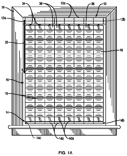
Vertical blind assembly

A modular shade includes at least one module that consists of a head rail unit, a foot rail unit, at least one intermediate rail unit, and a plurality of slat components.

Filed2010
LapsedAug 2025
OwnerSolo inventor
Drawing from US 9,732,561 B2Lapsed, fee not paid23 drawings
Industrial Equipment · US 9,732,561 B2

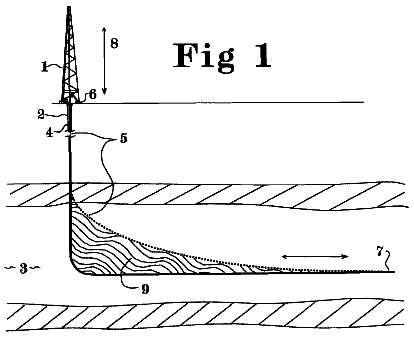
Method and apparatus for increasing well productivity

This patent application discloses method and apparatus to cut an extended slot connecting a well to a substantial cross section of a desired producing formation whereby material can flow freely between the formation and…

Filed2008
LapsedAug 2025
OwnerCarter, Jr.; Ernest E.