Lapsed, fee not paid4 drawings
Medical Devices · US 8,714,165 B2
Dental care device
A dental care device utilizing a shaft having a proximal end portion, a distal end portion, and an intermediate portion there between.
US 8,714,972 B2 · Inventors: Eichenberg; Tena
Sheet 1 of 5 from the published document. All sheets in the USPTO PDF
Disclosed is a bracket including a base plate on which two retaining wings are formed running parallel to one another and defining an intermediate space in which a wire arch may be held. The intermediate space has a trapezoidal structure such that the wire arch is always pushed upward under the elasticity of the bracket by the inclined retaining wings toward the retaining surfaces, such that the wire arch is held in the intermediate space in an aligned fashion without play. The cross sectional shape of the wire arch is selected such that no surface contact occurs in the intermediate space.
All 5 drawing sheets from the published document, cropped to the drawing.
What the patent claimed, word for word. All of it is now free to use.
The present invention relates to a self-ligating bracket and a wire arch consisting of a nickel-titanium alloy to be accommodated therein, with a retaining plate and at least a pair of spaced apart retaining wings integrally joined thereto, between which the wire arch is snapped in place, wherein the at least one retaining wing pair defines a gap that extends in the longitudinal direction of the wire arch, wherein the cross section of the gap exhibits a trapezoidal shape, and the retaining wings exhibit tongues at the ends remote from the retaining plate.
Brackets for regulating the position of teeth were originally made out of relatively rigid material, and the wire arch incorporated in the bracket was secured with ligatures. Developed later were the self-ligating brackets, in which the wire arch (archwire) was fixed in the bracket by means of a spring or clip (clip), so as to thereby largely avoid the time-consuming ligatures.
In the last several years, mention has also been made of self-ligating brackets consisting of elastic materials, which make it possible to press a wire arch between one or more pairs of retaining wings and snap it in place, so that the wire arch is held in the bracket.
Both plastics and shape memory alloys (e.g., comprised of nickel titanium) have been proposed as the used elastic materials. Precisely the latter material has become widespread in orthodontic technology, since the archwire is very often fabricated out of a nickel titanium alloy with a super-elastic behavior or memory effect.
Among other factors, the precision, and hence success, of orthodontic treatment depends on how the orthodontic arch is guided in the slot of the bracket. The objective here is to achieve the least clearance possible, even though too tight a fit will lead to elevated friction between the slot and arch, and hence slow the movement of the teeth.
Already known from document U.S. Pat. No. 5,356,289 A is an orthodontic bracket, which is made out of a nickel titanium alloy with memory effect or plastic, wherein two retaining wing pairs are present, between which an archwire with a rectangular cross section can be snapped in place. The cross section of the gap between the retaining wings is essentially rectangular as well.
The gap between the two retaining wings must inevitably be larger than the cross section of the archwire. As a consequence, the wire arch lies between the retaining wings with a clearance, resulting in a diminished precision of tooth movement, and hence a poorer treatment result. If the wire arch were to exactly match the shape of the gap between the retaining wings, the wire arch would be held free of clearance, but this cannot be accomplished in reality without simultaneously impeding the contouring of the wire arch.
The solution according to document U.S. Pat. No. 6,663,385 B is associated with precisely the same conceptual error. While the solution shown here essentially corresponds to the embodiment discussed above, the two retaining wings in this case are configured to extend over the entire length of the retaining plates. In order to increase the flexibility of the retaining wings, longitudinal grooves are provided on the wings in the area of the retaining plate, and intended to act as hinges. However, the problem remains the same. The wire arch in no way runs exactly straight, making it impossible to achieve a tight fit, as depicted here both in relation to the wire arch with a rectangular cross section and in the case of round wire arches. But in the final analysis, this document also shows a variant on FIG. 19 in which the gap between the two retaining wings has a trapezoidal design. The base surface of the trapezoid here runs flush with the surface of the retaining plate. As depicted on FIG. 19, this embodiment otherwise reflects the most obvious prior art of the present invention as defined at the outset, wherein the conicity of the thickness of the retaining wings is here intended to replace the longitudinal wings mentioned above, which produce the hinge-like effect. Accordingly, the same archwire with a rectangular cross section is used. Something other than the desired form-fit seating is also not disclosed here.
WO 2006/014378 shows another slightly modified version of a self-ligating bracket. In this solution, a round archwire is used, and the tongues are outwardly lengthened so that the archwire can be removed. However, we do not believe this is necessary, since the archwire is usually not reused, and thus can be extracted more easily by sectioning it in its longitudinal direction.
The object of the present invention is to realize a bracket and a wire arch with a correspondingly adjusted shape, which aligns itself after snapped in, causing it to be seated free of clearance.
This object is achieved by a bracket and a wire arch according to the preamble of claim 1, which exhibit the characterizing features of claim 1.
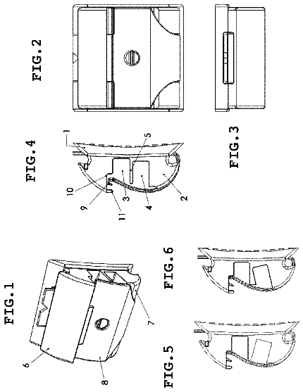
The drawing illustrates a preferred exemplary embodiment of the subject matter according to the invention, which is described based on the following specification with reference to the attached drawing. Shown on:
FIG. 1 is a side view of the bracket according to the invention with the accompanying wire arch inserted in the bracket, and
FIG. 2 is the same view of the same bracket with a conventional archwire having a round cross section.
FIG. 3 shows a cross section through a preferred wire arch for use with brackets according to the invention.
FIG. 4 shows a perspective view of the bracket according to the present invention with the round guidewire inserted.
FIG. 5 shows the same view with trapezoidal wire arch inserted.
A front view of a preferred embodiment of the bracket 1 according to the invention is shown on FIG. 1. 10 denotes the retaining plate, which exhibits an adhesive surface to be affixed to a tooth. The same bracket can here be situated both buccally and lingually. The adhesive surface of the retaining plate 10 is marked 10'. Visible in this view is the short side of the retaining plate 10, while the long side runs perpendicular to the drawing plane. Two retaining wings 11 spaced apart from each other are molded onto the surface of the retaining plate 10, essentially running mirror symmetrically relative to the longitudinal central axis. Viewed from the central longitudinal axis, the retaining wings 11 are essentially slightly curved toward the outside, and end in tongues 12. The bottom side of these tongues 12 terminally molded onto the retaining wings 11 exhibits retaining surfaces 13, which essentially run parallel to the surface of the retaining plate 10. The retaining wings 11 have a first, increasing section 14, in which the thickness of the wings increases in cross section, from the area near the retaining plate 10 toward the tongues 12. The area adjacent to this section and leading up to the tongues 12 forms a second section having a constant cross sectional area.
In addition to the already mentioned retaining surfaces 13 directed toward the retaining plate 10, the tongues 12 have upper sides 15. These sides 15 exhibit insertion ramps 16 that run from the upper side toward the retaining surfaces. These insertion ramps 16 make is possible to use a wire arch 2 that is round or a wire arch having a trapezoidal cross section, the narrow top surface 12 of which lies in this area of the insertion ramps, to outwardly deform the retaining wings 11 in a resilient manner simply by pressing on the wire arch 2, thereby snapping it in place in the gap 3 between the two retaining wings 11. The retaining wings 11 have inner lateral walls 111, which practically act as sliding ramps, and are able to slide the wire arch 2 into a defined upper position during the elastic restoration of the retaining wings 11. Certain conditions must be satisfied in relation to the wire arch 2 for the wire arch to now align itself and become seated in the gap 3 of the bracket 1 free of clearance. The wire arch 2 must be configured in such a way that, in the self-aligning, clearance-free position in the bracket 1, it comes to adjoin a respective abutment line of an inner lateral wall 111 of each retaining wing 11, in the process of which a resultant force directed toward the tongues 12 remains in place, holding the wire arch 2 in the defined position. In each case, the wire arch 2 is here spaced apart from the retaining plate 10 in the self-aligning, clearance-free retained position. As a consequence, the wire arch 2 is only aligned on the retaining wings 11, and non-positively abuts the tongues 12. Wire arches with varying cross sectional shapes can satisfy this condition. It is crucial that the cross sectional shape of the wire arch deviate from the cross sectional shape of the gap 3, and that the retaining wings 11 of the bracket 1 always be under a certain tension in the inserted state. Wire arches with preferred cross sectional shapes are those wire arches that exhibit either a round cross section or a trapezoidal cross section, wherein the isosceles, trapezoidal cross section exhibits a base surface slightly larger than the greatest distance between the two inner surfaces 111 of the retaining wings 11 with the latter slackened. The preferred diameter of a round wire arch 2 is roughly as large as a maximum inscribable circle in the gap 3 of the bracket 1. Of course, in order to again achieve the desired tension, this diameter must here be several percentage points greater to sustain a residual tension of the retaining wings 11. In this case, the wire arch will also bilaterally abut the pointed edges of the retaining tongues 12. The figure illustrates this situation in a clearly discernible manner.
Even in self-ligating brackets, ligatures or bands must often also be added to integrate all required tooth movements.
Therefore, it makes sense to provide an indentation 18 that runs approximately parallel to the retaining surfaces 13 in the bilateral faces 17 present on the bracket 1 arranged perpendicular to the running direction of the gap 3 in the transitional area between the retaining wings 11 and the terminal tongues 12. As a consequence, these indentations 18 run flush with the retaining surfaces 13. The dimensions of these indentations 18 must be adjusted to the used ligatures or rubber bands.
As evident from the perspective views on FIG. 4 and FIG. 5, the indentations 18 can be achieved by having the faces 17 of the two retaining wings 11 be slightly inclined from the retaining plate 10 to the tongues 12, so that the tongues project slightly on the front side relative to the retaining wings 11. This projection 18' now corresponds to the indentation 18.
The bracket 1 according to the invention provides both solutions involving several retaining wings arranged one after the other in the running direction of the wire arch, as well as variants with only one pair of retaining wings extending over the entire retaining plate length.
If only two retaining wings 11 extending over the entire length of the retaining plate 10 are present, it would make sense to introduce window-like openings 19 in the retaining wings 11, as clearly evident from the figures. In addition to the shapes of the openings or indentations depicted here, the bracket 1 according to the invention can of course exhibit differently configured indentations useful for incorporating a ligature.
FIG. 3 shows a cross section through a preferred embodiment of a wire arch. As already mentioned above, even though wire arches with various cross sectional shapes are possible, provided they satisfy the aforesaid conditions, a wire arch with a cross sectional shape in the configuration of an isosceles trapezoid is especially preferred. In this variant shown on FIG. 3, the wire arch exhibits a top surface 21 and a wider lower base surface 20 running parallel thereto. As a consequence, the lateral surfaces 22 run mirror symmetrically to the central, vertical longitudinal plane. The angle between the lateral surfaces 22 and base surface 20 is hence bilaterally acute, while the corresponding upper angle between the top surface 21 and lateral surface 22 is obtuse. Respective longitudinal edges 23 run between the base surface 20 and lateral surface 22. The upper longitudinal edges 24 run between the top surface 21 and lateral surfaces 22. These longitudinal edges 23 and 24 preferably exhibit a rounded configuration to optimize the way in which these self-centering edges slide along the inner lateral walls 111 of the retaining wings 11. However, the precondition for a self-centering, clearance-free seating is that the acute angle at the edge 23 between the base surface 20 and the lateral walls 22 be smaller than the angle included by the retaining surface 13 and the inner lateral wall 111 of the retaining wings 11. The angle included by the two lateral surfaces 111 in their extension with each other must necessarily be greater than the angle that the inner lateral walls 111 of the retaining wings 11 would include between each other, also in the extension with each other.
Because nickel titanium alloys with a memory effect are used, an elastic restoration first takes place when pressing in the wire arch, or archwire, which forces the wire arch into the desired clearance-free, abutting position as described before, wherein the archwire is pressed against the retaining surfaces, while the lateral surfaces are only guided. After a certain time and exposed to the warmth n of the oral cavity, a plastic restoration then takes place, and hence a relatively tight abutment of the retaining wings on the lateral surfaces 22 of the archwire, thereby producing a relatively tight abutment, and thus increasing the friction between the slot formed by the retaining wings 11 and the retaining surfaces 13 and the wire arch 2. This causes the teeth to move more slowly. However, this is preferred in dental orthopedics, since a return movement that also always happens after treatment is significantly reduced. The same effect is also encountered in wire arches with a round cross section, since the surfaces 111 of the retaining wings 11 here cling slightly flatly to the wire to a slight extent as well.
When working with a wire arch
(archwire) having a round cross section, the latter must also be adjusted to the gap
of the bracket
when selecting the size. In principle, the diameter of the wire arch must be large enough that the retaining wings
under a pretension move the wire arch
up, until it comes to abut the bottom side of the tongues (12). This is generally satisfied when the diameter of the wire arch is greater than the diameter of the maximum circle inscribable in the gap (3). Of course, there is a limit to how much larger the diameter of the wire arch can be relative to the aforementioned inscribable circle. However, experience will guide the expert in properly dimensioning the latter. In principle, it is enough that the diameter be only a few percentage points larger than the maximum circle inscribable in the gap, in particular between 2 and 20%.
As already mentioned, cross sectional shapes other than the two embodiments of the archwire or wire arch shown here are also conceivable. For example, the lateral surfaces 22 of the wire arch 2 can bulge outward slightly. An archwire with a triangular shape is also conceivable. In this case, the cross section of the gap 3 is also such that the trapezoidal form also exhibits a very short top surface (base surface on the retaining plate 10 between the retaining wings 11).
1 Bracket 2 Wire arch (archwire) 3 Gap 10 Retaining plate 10' Adhesive surface 11 Retaining wing 12 Tongues 13 Retaining surfaces 14 Increasing section of retaining wings 15 Side remote from retaining plate 16 Insertion ramps 17 Face of bracket 18 Indentation 18' Projection 19 Window-like opening 20 Base surface 21 Top surface 22 Lateral surfaces 23 Longitudinal edges of base surface 24 Longitudinal edges of top surface 111 Inner lateral wall of retaining wing 11
About 2,704 words. The USPTO PDF has it with every drawing.
Fees are due 3.5, 7.5 and 11.5 years after grant. This patent expired on May 6, 2026, so the fee marked "not paid" was the one that went unpaid.
SELF-LIGATING BRACKET
Filed Jul 2010 · published May 2012Self-ligating bracket
Filed Jul 2010 · granted May 2014Earlier publications, parents and continuations. None of them can still be enforced, or this patent would not be listed.
Prior art cited by the examiner or applicant. Useful when you check your own idea for novelty.
Everything on this page comes from the documents linked above.