Cross-reference to related application
This application is a National Stage entry of International Application No. PCT/GB2008/003766 filed Nov. 6, 2008, and which claims priority to applications GB 0721714 filed Nov. 6, 2007, GB 0807347.0 filed Apr. 23, 2008, and GB 0816989.8 filed Sep. 17, 2008, the entire specification, claims and drawings of which are incorporated herewith by reference in their entirety.
Field of the invention
The invention relates to sterilisation systems suitable for clinical use, e.g. on or in the human or animal body. For example, the invention may provide a system that can be used to destroy or treat certain bacteria and/or viruses associated with the human or animal biological system and/or the surrounding environment. This invention is particularly useful for sterilising or decontaminating enclosed or partially enclosed spaces, e.g. hospital bed spaces.
Background to the invention
Bacteria are single-celled organisms that are found almost everywhere, exist in large numbers and are capable of dividing and multiplying rapidly. Most bacteria are harmless, but there are three harmful groups; namely: cocci, spirilla, and bacilla. The cocci bacteria are round cells, the spirilla bacteria are coil-shaped cells, and the bacilli bacteria are rod-shaped. The harmful bacteria cause diseases such as tetanus and typhoid.
Viruses can only live and multiply by taking over other cells, i.e. they cannot survive on their own. Viruses cause diseases such as colds, flue, mumps and AIDS.
Fungal spores and tiny organisms called protozoa can cause illness.
Sterilisation is an act or process that destroys or eliminates all form of life, especially micro-organisms. During the process of plasma sterilisation, active agents are produced. These active agents are high intensity ultraviolet photons and free radicals, which are atoms or assemblies of atoms with chemically unpaired electrons. An attractive feature of plasma sterilisation is that it is possible to achieve sterilisation at relatively low temperatures, such as body temperature. Plasma sterilisation also has the benefit that it is safe to the operator and the patient.
Plasma typically contains charged electrons and ions as well as chemically active species, such as ozone, nitrous oxides, and hydroxyl radicals. Hydroxyl radicals are far more effective at oxidizing pollutants in the air than ozone and are several times more germicidal and fungicidal than chlorine, which makes them a very interesting candidate for destroying bacteria or viruses and for performing effective decontamination of objects contained within enclosed spaces, e.g. objects or items associated with a hospital environment.
OH radicals held within a "macromolecule" of water (fog drop) are stable for several seconds and they are 1000 times more effective than conventional disinfectants at comparable concentrations.
A recent article.sup.1 considers the use of OH radicals produced by strong ionisation discharges to eliminate microbial contamination. In this study, the sterilisation effect on E. coli and B. subtilis is considered. The bacteria suspension with a concentration of 10.sup.7 cfu/ml (cfu=colony forming unit) was prepared and a micropipette was used to transfer 10 .mu.l of the bacteria in fluid form onto 12 mm.times.12 mm sterile stainless steel plates. The bacteria fluid was spread evenly on the plates and allowed to dry for 90 minutes. The plates were then put into a sterile glass dish and OH radicals with a constant concentration were sprayed onto the plates. The outcomes from this experimental study were:
1. OH radicals can be used to cause irreversible damage to cells and ultimately kill them;
2. The threshold potential for eliminating micro-organisms is ten thousandths of the disinfectants used at home or abroad;
3. The biochemical reaction with OH is a free radical reaction and the biochemical reaction time for eliminating micro-organisms is about 1 second, which meets the need for rapid elimination of microbial contamination, and the lethal time is about one thousandth of that for current domestic and international disinfectants;
4. The lethal density of OH is about one thousandths of the spray density for other disinfectants--this will be helpful for eliminating microbial contamination efficiently and rapidly in large spaces, e.g. bed-space areas; and
5. The OH mist or fog drops oxidize the bacteria into CO.sub.2, H.sub.2O and micro-inorganic salts. The remaining OH will also decompose into H.sub.2O and O.sub.2, thus this method will eliminate microbial contamination without pollution. .sup.1 Bai et al, "Experimental studies on elimination of microbial contamination by hydroxyl radicals produced by strong ionisation discharge", Plasma Science and Technology, vol. 10, no. 4, August 2008
Summary of the invention
At its most general, the invention provides a sterilisation system arranged controllably to generate and emit hydroxyl radicals.
According to the invention, there may be provided sterilisation apparatus comprising an applicator having a hydroxyl radical generating region and an outlet for directing generated hydroxyl radicals out of the hydroxyl radical generating region towards a region to be sterilised; an enclosure for confining the hydroxyl radicals in the region to be sterilised; a power generator connected to deliver energy into the hydroxyl radical generating region; and a mist generator connected to deliver water mist (which may also mean moisture or fog) into the hydroxyl radical generating region, wherein the apparatus is configured to create a high impedance at the hydroxyl radical generating region when water mist and energy are delivered thereto thereby to create an ionisation discharge for generating hydroxyl radicals for delivery out of the applicator or device.
This system may be used to produce OH radicals for applications relating to hospital ward or bed space or operating theatre decontamination or sterilisation.
The apparatus may include a coaxial assembly having an inner conductor surrounded by and separated from an outer conductor, wherein the inner conductor tapers at its distal end to concentrate an electric field in the hydroxyl radical generating region to promote ionisation discharge when water mist and microwave energy are delivered thereto. The inner (centre) conductor may be part of a coaxial impedance transforming network arranged to generate a high enough electric field to enable a useful non-thermal plasma to be struck or an ionisation discharge to take place.
The apparatus may include a gas feed connected to deliver gas into the hydroxyl radical generating region, wherein the created ionisation discharge is a plasma of the gas. The plasma may be combined with the mist to produce OH radicals with a concentration that is suitable to decontaminate a range of isolated regions or spaces defined by a flexible or portable enclosure that can be filled with the radicals produced by the applicator or device. The enclosure enables the OH radicals to be concentrated and prevents the whole ward being flooded with OH radicals.
The mist generator may include a valve contained within the inner conductor of the coaxial assembly, the valve having an outlet located to deliver mist at the distal end of the inner conductor. The valve may be a needle valve. The needle valve may be operated mechanically, as in the case of an air brush arrangement, or electronically as in the case of a fuel injection system, to enable the water (or other fluid) to be introduced into the centre conductor under pressure.
A nozzle may be included at the distal end of the conductor (needle valve) to act as an atomiser to enable a controllable mist to be produced. The valve used to control the flow of water (or other fluid) along the centre conductor may be a solenoid valve, which is an electromechanical valve controlled by sending an electrical current through a solenoid to change the state of the valve, i.e. when the current is flowing through the winding of the solenoid, the solenoid produces a magnetic field which moves a plunger, or a rod of magnetic material, in a particular direction to open the valve and allow the flow of water along the centre conductor, and, when the current ceases, the rod may move back to a rest position, i.e. the valve is closed and the flow of water along the centre conductor is cut off.
In a particular embodiment, the valve may be connected at one end to a spring, which may be used to keep the valve closed when no field is applied and compressed to cause the valve to open when the field is applied. When the valve is open, the water (or other fluid) flows into the centre conductor and the gas (or compressed air, or gas mixture) is used to draw the water from the centre conductor to produce a mist at the nozzle. The gas also enables plasma to be produced at the distal tip of the centre conductor due to ionisation of the gas, caused by the high electric field set up at the distal tip due to the microwave or RF field and the particular antenna used, and the plasma combines with the mist to produce a concentration of OH radicals suitable for destroying a range of bacteria or viruses. When the valve is closed, the water (or other fluid) is unable to flow along the centre conductor, but the gas (or compressed air, or gas mixture) is still able to produce a plasma due to ionisation of the gas (or compressed air, or gas mixture) caused by the high electric field set up at the distal tip due to the microwave field produced by the generator and the particular antenna or resonator structure used. This plasma may also be used to destroy a range of bacteria or viruses.
If the applicator is set up to produce plasma and OH radicals through controlled mist generated inside the centre conductor, the gas inlet may be positioned downstream of the valve used to control the flow of water along the centre conductor. In certain instances it may be preferable for the applicator to use a mechanical valve arrangement. In this instance, the mechanical valve mechanism, the means of creating an E-field high enough to ionise the gas (or mixture of gases), the supply of water and the compressed gas (or mixture of compressed gases) are integrated into a handheld device. The device may take the form of a pen and may be used to sterilise a number of objects used in a clinical environment or a range of surfaces. The compressed gas (or gas mixture) may come from an air compressor and/or a gas cylinder(s) and is introduced into the applicator using a suitable connection tube. The connections to the centre conductor that act as inlets for the water supply and the compressed gas (or gas mixture) must be such that the electromagnetic field set up inside the applicator structure is unaltered. This may require the feed tube to be made from a low loss dielectric material or it may be necessary to set-up the feed lines as an arrangement of tuning stubs. In this particular arrangement, a mechanical valve is included to control the flow of the compressed gas (or gas mixture) and to introduce the water into the centre conductor. Upon actuation of a button or trigger, a needle valve releases a flow of water and simultaneously releases a flow of compressed gas into the system. The compressed gas draws water from the distal end of the centre conductor and the water molecules are atomised, due to the inclusion of a suitable nozzle, as the water exits the centre conductor. In operation, the user may depress a button located on the outer body of the applicator when it is desired to produce the OH radicals. It is preferable for the solenoid valve to be contained within the applicator as the valve should release the water, which may be under pressure, straight into the centre conductor (needle) to enable a mist to be instantaneously produced at the distal end of the applicator, which will combine with the plasma to produce OH radicals.
Although it is preferable for the system to contain the valve in the applicator, this invention is not limited to this arrangement, i.e. the valve control may be contained within the instrument containing the microwave generator and associated control electronics. It may be preferable for the water to be fed using a gravity fed mechanism rather than a pump.
Water may be introduced into the system downstream of the gas supply in order to use the gas to withdraw or assist with the withdrawal of the water from the centre conductor. In this particular arrangement, the valve assembly will be changed to allow the gas to flow past the valve, i.e. the valve and seal arrangement will be reconfigured.
It may also be preferable for the gas (or gas mix) to be directly combined with the water rather than having the two separated. Where the water supply and the gas supply (or mixture) is separated, it is preferable for the gas (or gas mixture) to be fed into the centre conductor downstream from the water supply, i.e. closer to the distal tip. This is because the applicator is able to produce plasma or OH radicals in accordance with the state of the needle valve, i.e. if the valve is open OH will be created and if the valve is closed plasma will be created. This enables the applicator, or instrument, to be used in a range of applications relating to the human or animal body and external environments. For example, it may be used to kill or destroy prions existing on the surface of surgical instruments.
In an alternative arrangement, the applicator may comprise a waveguide cavity containing the hydroxyl radical generating region, the waveguide cavity having a coupler or launcher located therein for delivering microwave energy from the microwave radiation generator to the hydroxyl radical generating region, and a mist inlet for delivering fog, moisture or mist into hydroxyl radical generating region. In a particular embodiment, the microwave energy generating device may be directly connected to the waveguide cavity where the OH radicals are created.
An antenna (e.g. dipole antenna) may be located in the waveguide cavity to concentrate an electric field in the hydroxyl radical generating region to promote ionisation discharge when water mist and microwave energy are delivered thereto. The mist inlet may be a passageway through the antenna.
The waveguide cavity may include an impedance adjustor arranged to control the impedance at the hydroxyl radical generating region when water mist and microwave energy are delivered thereto. The impedance adjustor may be arranged to selectively occupy either (i) a strike state in which a first impedance for creating the ionisation discharge is exhibited at the hydroxyl radical generating region when water mist and microwave energy are delivered thereto, or (ii) a maintenance state in which a second impedance for maintaining the ionisation discharge is created at the hydroxyl radical generating region when water mist and microwave energy are delivered thereto, the second impedance being lower than the first impedance. The ionisation discharge may be created repeatedly (or plasma may be struck repeatedly) by pulsing the energy from the microwave generator. In this particular instance, only one impedance state may be required.
The microwave energy may be delivered to the waveguide cavity via a feed line, and wherein the impedance adjustor may comprise either (a) a stub tuner having one or more stubs that are adjustably insertable into the feed line; (b) a stub tuner having one or more stubs that are adjustably insertable into the waveguide cavity; or (c) one or more fixed stubs connected in shunt to the feed line that are electronically switchable between an open circuit configuration and a short circuit configuration; or (d) one or more variable capacitors connected in series and/or parallel to the feed line.
The mist generator comprises a ultrasonic fog generator.
The system may comprise a controllable microwave or RF power generator or plurality of generators; a controllable supply of gas (or gas mixture); a controllable supply of mist or fog; a single or plurality of applicators that produce suitable plasma and/or suitable concentrations of OH radicals: a cable assembly or means of transferring the microwave or RF power from the generator(s) into the applicator(s); an enclosure to enable suitable concentrations of OH radicals to be built up or established; a control system to control the operation of the microwave (or RF) generator, the gas flow and mixing system, and the mist or fog generator; a means of introducing the applicator(s) into the space or enclosure where decontamination or sterilisation is to be performed; a user interface to enable the user to control the plasma or OH radical sterilisation, decontamination or cleaning system, and a means of monitoring the OH concentration and the effectiveness of the cleaning process (this may be an external process or instrument).
The apparatus may use an integrated applicator (in which the mist and plasma is generated) or may use a separate first applicator to produce the plasma and a separate second applicator to produce the mist or fog. In the latter arrangement, the mist or applicator is then coupled to the plasma applicator using an abutment arrangement to enable the mist to be effectively coupled to the plasma to enable OH radicals of suitable concentration to be generated. The OH radicals are introduced into an enclosed environment and the environment is filled with a concentration of radicals suitable for killing bacteria or contaminants that exist inside the enclosed section. A plurality of integrated or separate component applicators may be used to introduce the OH radicals into the enclosed environment at a number of ports arranged around the periphery of the enclosure. The device used to create the ionisation discharge and the device to create the mist may be separate units or sub-assemblies and the two units may be placed in two different locations within the flexible enclosure. The instrumentation containing the microwave generator, the gas (or mixture of gases), the mist generator, the control system and the user interface is preferably located outside the enclosed environment to enable the user to control the system without being exposed to high concentrations of OH radicals.
The enclosure may be a portable arrangement that can be moved around inside a hospital, e.g. the enclosure may take the form of a large umbrella or a tent or a large balloon. The purpose of the enclosure it to contain and confine the hydroxyl radicals therein. This may serve both to protect an external environment from unwanted effects and to concentrate the hydroxyl radicals in the region to be sterilised. It is highly desirable for the enclosure easily transportable without being damaged. It may be desirable for the enclosure to be moved around in a hospital ward from one bed-space to the next to perform a serial decontamination process without the need to close the hospital ward, thus reduce downtime or create additional resources for treating or caring for patients, therefore the enclosure should ideally be suitable to enclose an area containing a bed, a bed side cabinet and any other bed space furniture that may be present in the area. It may be preferable for the flexible enclosure to be double skinned or consist of a plurality of walls, skins or membranes in order to ensure that as many OH radicals as possible are contained within the enclosed space and that a high concentration of OH radicals can be maintained.
The lifetime of OH radicals in air may be 1 to 3 seconds. If the enclosure is portable, there may in use be gaps at the interface between its edges and the edges of the region to be sterilised. To prevent OH radical escaping, the surface of the enclosure, especially at the edges, may be coated with a material that acts as a good absorber of OH radicals.
Alternatively or additionally, the enclosure may seal the region to be sterilised. The seal may be effected by attachment elements, or, for parts of the enclosure which contact a floor surface, weighted elements (e.g. containing sand or the like) that promote good contact between the enclosure and floor. Instead of a physical seal, the OH radicals may be confined in the enclosure by a back pressure generated at the edges therefore, e.g. acting to directly gas moving out of the enclosure back into the enclosure.
One or more fans may be provided to distribute the air containing OH radical within the space in the enclosure. The fan(s) may be located inside the enclosure.
The OH radicals produced by this system may oxidise the bacteria contained within the bed space into CO.sub.2, H.sub.2O and micro inorganic salts. The remaining OH radicals may decompose into H.sub.2O and O.sub.2 and so the system should eliminate microbial contamination without pollution--this is of particular significance in the intended application since patients and healthcare workers will be present during the decontamination process, i.e. a patient may be located in a bed either side of the space where decontamination is taking place during the time this process is taking place. The fact that harmful by products may not be produced by the sterilisation process means that it may not be necessary to totally seal off the bed space area being decontaminated, i.e. it may not be necessary to put sealing tape around the edges of the enclosure where the closure comes into contact with the floor and it is not necessary to use air tight seals around the input ports where the OH radicals are introduced into the enclosure. This is also beneficial in terms of decontamination time, i.e. the portable enclosure can be moved from one bed space to the next in a matter of minutes.
However, it may also be beneficial to concentrate the OH radical in an enclosed region to ensure 100% bacteria or bug kill rate, and it may be undesirable to have OH radicals continuously filling spaces where patients or staff are present. The system presented herein may create high densities of OH radicals in a controllable manner to kill all bacteria or viruses or bugs in a partially enclosed region where no harm can be caused to patients or staff that are present in regions nearby the partial enclosure or positioned elsewhere within the hospital ward.
The flexible structure means that the enclosure may be moved and set up by a single member of hospital staff. The generator or instrumentation may be located on the top of a small trolley or contained within a bespoke enclosure with wheels, thus this sterilisation process is not resource intensive. Once the bed space has been decontaminated, the patient can be put straight back into bed with the assurance that the OH radical system has totally decontaminated the area where he/she is going to be located; this should provide a high level of patient comfort and peace of mind.
The instrumentation used to generate the OH radical supply (including gas bottle(s) and water cylinder) may be housed in an enclosure with wheels so that it can be moved from bed to bed or ward to ward. The portable enclosure may be made from a fabric material or a plastic sheet with metal struts to give it support, i.e. a similar arrangement to a camping tent or an umbrella may be used.
The apparatus may include a means of recycling the OH radicals and/or the gas (or mixture of gases) back into the system to increase the efficiency of operation in terms of minimising gas and electrical energy used and reducing the introduction of stray OH radicals into spaces around the enclosure where patients or staff may be present. The system for recycling the OH radicals may consist of an arrangement comprising: one or two chambers, a first pump (motor) to remove OH radicals from the system, a second pump (motor) to reintroduce radicals back into the enclosure or into the applicator and an arrangement of pipes or tubes. The system may also include an arrangement of one way valves. It may be preferable to use a plurality of outlet and inlet pipes to ensure that the radicals are evenly or uniformly circulated or distributed within the enclosure. The system may also contain a fan or an arrangement of fans to ensure that the radicals inside the enclosure are moved around within the decontamination space to ensure that all bacteria within the space is successfully destroyed. Where the gas is extracted and fed back into the applicator, a Y-type combiner may be used to recombine the recycled gas with the gas (or gas mix) produced by the cylinder(s). The ionisation discharge may be created using air or compressed air; in this instance a compressed air generator may be used to replace the gas cylinder(s).
This arrangement may also be used to feed the gas (or gas mixture) back into the applicator(s) to produce more plasma to enable new radicals to be generated. In this arrangement, the gas (or gas mixture) that gets pumped back into the chamber is pumped back out and fed into the applicator or stored in a separate chamber ready for use. The recycled gas and the gas from the main cylinder(s) is/are then combined using a Y-type gas connector or the like. This will reduce the demand on the external gas supply.
The apparatus may include a means of measuring the spectral content (wavelength and magnitude) of the energy produced by the system at the distal end of the applicator where the plasma/OH is emitted. The measurement system may comprise an arrangement of photodiodes or light detectors and associated signal conditioning, and the information from the diodes may be fed into the microprocessor or control system to enable the wavelength and the intensity of the UV and plasma produced at the output of the system to be controlled. Photodiodes are semiconductor light sensors that generate a current or voltage when the P-N junction in the semiconductor is illuminated with light.
The intensity and wavelength information may be fed back into the system to enable adjustments of microwave power level, gas flow rate and gas mixture to be made in order to optimise the generation of the OH radicals. Particular devices that may be used to implement the detectors include: Si photodiodes, Si PIN diodes, multi-element type Si photodiodes and Si avalanche photodiodes (APDs). It may be preferable to integrate a mini spectrometer arrangement into the applicator or the output of the system to provide the function of wavelength and intensity measurement. In such arrangements, the following types of sensors may be used: CCD sensors, CMOS linear sensors and InGaAs sensors. A particular device that may be considered is a C10082MD or C10083MD mini-spectrometer from Hamamatsu, which employs a CMOS linear image sensor as the detector.
These devices can be used to measure light intensity within the UV and the near IR range of wavelengths. A range of sensors may be employed to enable light intensity measurements to be made within the 200 nm to 2200 nm wavelength range.
For the system introduced here, it may be preferable to use a polychromator type arrangement whereby a grating is used as the wavelength dispersing element and an array type detector is placed along the focal plane of the focussing lens. Polychromators are designed to allow simultaneous detection of multiple spectra, which could be advantageous for use in our system.
The impedance adjustor may be arranged as a dynamically controlled or statically controlled matching network or tuner to enable the microwave energy used to create the plasma to be impedance matched into the high impedance state required to strike the plasma and the low impedance state required to sustain or maintain the plasma. Alternatively, a fixed tuning arrangement may be provided that enables an ionisation discharge to occur on the leading edge of each pulse of microwave power. Such an arrangement will ensure that the microwave power generating device, i.e. a magnetron, is protected from damage due to frequently occurring gross impedance mismatches during the plasma strike or ionisation discharge occurrence, i.e. the output impedance of the magnetron will be matched to the impedance that is set up within the cavity when ionisation discharges or plasma strikes occur. It may be preferable to operate the system in pulsed mode.
The system may also include a means of measuring wavelength and intensity of the plasma/UV/OH produced at the output of the system (the applicator) and this information may be used in a feedback loop to control the wavelength and intensity of the energy produced by the system.
In the current invention, the power level may be adjustable in a controlled manner, e.g. the microwave energy can be modulated in a controlled manner using at least one modulator or means of modulation.
The invention also draws upon the availability of moisture that may be produced either through the environment where the plasma is being generated (applications within the body) or by introducing moisture or fog or mist into the applicator through external means, e.g. fog produced by an ultrasonic transducer and a vessel of water. The introduction of fog or mist or moisture may be used to enable hydroxyl radicals to be produced, which are known to be effective for killing bacteria or fungi.
The apparatus may include means for delivering the generated OH radicals into an open space or a flexible or portable enclosure where they are used to sterilise or decontaminate the space contained within the enclosure. In this particular arrangement, the OH radicals generated inside the waveguide cavity may be blown through the cavity using a first fan (or plurality of fans) and then pumped out of the waveguide cavity using a pump or a second fan (or plurality of fans), e.g. a first fan is connected to the input wall of the waveguide cavity and a second extraction fan is connected to the output wall of the waveguide. It may be preferable to use only one fan connected at the input end to blow the radicals through the cavity or it may be preferable to channel a portion of the radicals produced at the output back to the input end in order to prevent large quantities of air being blown into the waveguide cavity, which may have a detrimental effect on the OH radicals produced at the output of the waveguide cavity. In such an arrangement, microwave energy may be coupled into the cavity using an E-field or an H-field probe and the ionisation discharge required to create the OH radicals may be created using a dipole antenna arrangement made up of a quarter wavelength monopole and a quarter wavelength return, placed inside the waveguide cavity at a region where the E-field is a maximum in order to assist the breakdown process, and/or a tuning arrangement, e.g. a stub tuner, may be used to set-up a suitable impedance or microwave field to enable the ionisation discharge to occur. The dipole arrangement may consist of a metallic rod with a sharp point at the distal end, that has a length equal to a quarter of the wavelength at the frequency of operation, connected to the centre of a flat disk that has a diameter equal to half the wavelength at the frequency of interest, and located inside the waveguide cavity to create the necessary ionisation discharge. In this particular arrangement, both the rod and the disk are preferably made from a material that has a high conductivity, i.e. copper or brass. The mist or fog required to create the OH radical may be provided by an ultrasonic transducer placed inside a vessel containing water (or covered by a continuous supply of water). This arrangement may be placed inside the waveguide cavity at a location close to where the ionisation discharge is taking place or may be connected externally to one of the waveguide walls, where a hole has been made and a wire mesh or grid or arrangement of holes or an arrangement of slots is used to allow the fog to enter the waveguide cavity, but not allow microwave energy to be radiated through the hole. Alternatively the mist may be generated by feeding a supply of pressurised water through a hollow channel formed in the centre of the quarter wavelength monopole (described above). A nozzle may also be included at the end to enable a supply of atomised water molecules to emanate from the end of the centre conductor to create the desired mist, which can then be instantly turned into OH radicals as soon as the ionisation breakdown or discharge occurs at the tip of the same nozzle where the mist is being generated.
If a magnetron is used as the microwave source, its output (normally a E-field antenna) may be coupled directly into the waveguide cavity.
As mentioned above, a gas (or a mixture of gases) may be introduced into the waveguide cavity to assist in the ionisation discharge process and create energy at the most appropriate wavelength to enable the OH radicals to be generated when this energy is coupled with the mist or fog present inside the waveguide. It may be preferable to use the gas (or gas mixture) used to create the ionisation discharge (or the plasma) to also push water through the centre of the monopole or to assist in creating the mist.
The monopole may be replaced with an electrode that has a pointed end, or spike. The electrode may be positioned opposite one of the tuning stubs such that the tip of the electrode and the end of the tuning stub are in close proximity. The tip of the electrode and the tip of the particular tuning stub may be pointed and made from a material that can withstand high temperatures, e.g. tungsten. In this arrangement, the tuning stubs should be set such that the E-field generated in this region is a maximum to enable the electrode to assist in the ionisation discharge process.
In the implementation of this particular aspect of the current invention it may be preferable to use a microwave oven cavity to provide the field required to cause the ionisation breakdown necessary to generate the OH radical concentration, e.g. an industrial size microwave oven that can produce microwave power levels in excess of 1 kW may be used. It may also be preferable to partially pressurise the cavity in order to reduce the breakdown voltage required to create the ionisation discharges.
The dipole may be replaced with an alternative structure suitable to create the ionisation discharges or high intensity UV, e.g. a vacuum tube may be placed inside the cavity or the cavity walls may be reduced in certain locations within the waveguide cavity or an electrode with a point or spike on the end may be introduced to create the necessary ionisation discharges.
In this specification microwave frequency may be used broadly to indicate the range 400 MHz to 100 GHz, but preferably the range 1 GHz to 60 GHz. Specific microwave frequencies that have been considered are: 900 MHz, 2.45 GHz, 3.3 GHz, 5.2 GHz, 10 GHz, 14.5 GHz and 24 GHz. RF frequency may be used broadly to indicate the range 50 kHz to 500 MHz. Specific RF frequencies that may be of interest are 100 kHz, 500 kHz, 13 MHz, 27.12 MHz, 40.68 MHz, 50 MHz and 100 MHz.
Other independent aspects of the invention may include the applicators discussed herein and methods of generating OH radicals for sterilisation.
Brief description of the drawings
Features of the invention are now explained in the detailed description of examples of the invention given below with reference to the accompanying drawings, in which:
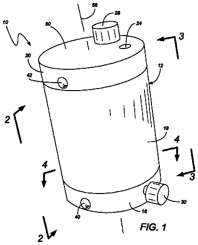
FIG. 1 is a schematic diagram of a sterilisation system for producing hydroxyl radicals that is an embodiment of the invention;
FIG. 2 is a schematic diagram of a sterilisation system for producing hydroxyl radicals having a gas extraction and recycling system;
FIG. 3 is a schematic diagram of another sterilisation system for producing hydroxyl radicals having a gas extraction and recycling system;
FIG. 4 is a schematic diagram of yet another sterilisation system for producing hydroxyl radicals having a gas extraction and recycling system;
FIG. 5 is a schematic diagram of another sterilisation system for producing hydroxyl radicals having an automatic tuning mechanism integrated in a plasma applicator;
FIG. 6 is a schematic diagram of another sterilisation system for producing hydroxyl radicals without an automatic tuning mechanism;
FIGS. 7(a), 7(b) and 7(c) are schematic views of a needle valve comprising a solenoid;
FIG. 8 is a longitudinal cross-sectional view of a coaxial plasma applicator having two impedance transformers and an inbuilt valve in an open configuration;
FIG. 9 is a longitudinal cross-sectional view of the coaxial plasma applicator shown in FIG. 8 in a closed configuration;
FIG. 10 is a partial longitudinal cross-sectional view of a coaxial plasma applicator having an inbuilt valve operated using two windings in an open configuration;
FIG. 11 is a partial longitudinal cross-sectional view of the coaxial plasma applicator shown in FIG. 10 in a closed configuration;
FIG. 12 is a full longitudinal cross-sectional view of the coaxial plasma applicator shown in FIG. 10;
FIG. 13 is a partial longitudinal cross-sectional view of the coaxial plasma applicator shown in FIG. 11;
FIGS. 14(a) and 14(b) are schematic views of the control circuit for a valve to be used in an applicator according to an embodiment of the invention;
FIG. 15 is a longitudinal cross-sectional view of a coaxial plasma applicator having four impedance transformers and an inbuilt valve in an closed configuration;
FIG. 16 is a longitudinal cross-sectional view of a coaxial plasma applicator having two impedance transformers in which gas and mist are fed through inlet in the outer conductor of a coaxial assembly;
FIG. 17 is a longitudinal cross-sectional view of a coaxial plasma applicator having four impedance transformers in which gas and mist are fed through inlet in the outer conductor of a coaxial assembly;
FIG. 18 is a schematic view of the control circuit for a valve to be used in an applicator according to an embodiment of the invention;
FIG. 19 is a schematic diagram of a sterilisation system for producing hydroxyl radicals in which the energy source is an RF generator and the applicator consists of a coaxial structure with a single centre conductor;
FIG. 20 shows an embodiment of an RF generator suitable for use in the system shown in FIG. 19;
FIGS. 21(a) and 21(b) are views of a first plasma applicator according to an embodiment of the invention;
FIGS. 22(a) and 22(b) are views of a second plasma applicator according to another embodiment of the invention;
FIGS. 23(a) and 23(b) are views of a third plasma applicator according to yet another embodiment of the invention;
FIGS. 24(a) and 24(b) are views of a fourth plasma applicator according to yet another embodiment of the invention; and
FIGS. 25(a) and 25(b) are views of a fifth plasma applicator according to yet another embodiment of the invention.
Detailed description
Further Options and Preferences
This invention relates to a system and method of generating hydroxyl radicals in a range of concentrations to kill bacteria or contaminants associated with hospital environments, outpatient surgeries or other areas where is it required to perform safe and effective decontamination. The invention may also be used to kill bacteria or bugs that exist within carpets or other flooring materials in hospitals, offices or domestic homes.
The system introduced here uses a combination of microwave or RF energy, a gas (or gas mixture) and a mist (or moisture) generator to produce a controllable supply of OH radicals that have a high enough concentration to be useful to perform effective decontamination of enclosed spaces. In this invention, the enclosed space may be defined by a portable or flexible enclosure, which may be an integral part of the system.
The description continues in the full USPTO document.
 Lapsed, fee not paid10 drawings