 Lapsed, fee not paid31 drawings
Telecom & Networks · US 8,571,073 B2
Frame mapping apparatus and frame mapping method
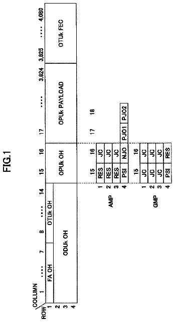
An apparatus for mapping multiple lower-speed signal transmission frames to a higher-speed signal transmission frame.
US 8,571,091 B2 · Assignee: Nokia Siemens Networks Oy · Inventors: Dalsgaard; Lars et al.
Sheet 1 of 15 from the published document. All sheets in the USPTO PDF
Systems and methods for providing half duplex user equipment in a packet based radio frequency signaling communication system. User equipment with half duplex receiver and half duplex transmitter on IC providing a transceiver capability performs a cycle of receiving downlink messages for a predetermined number of sub frames, shifting to a transmit mode, transmitting uplink messages for the predetermined number of sub frames, shifting to a receive mode, and repeating the cycle of half duplex sub frames. A discontinuous reception function performs a DRX protocol wherein power is reduced to the transceiver for a period of time. A determination is made at the end of the discontinuous reception period to see if the half duplex cycle is at an uplink sub frame; if so, the end of the discontinuous reception is shifted by the user equipment to a downlink sub frame by adding a delay.
As wireless communication systems such as cellular telephone, satellite, and microwave communication systems become widely deployed and continue to attract a growing number of users, there is a pressing need to accommodate a large and variable number of communication subsystems transmitting a growing volume of data with a fixed resource such as a fixed channel bandwidth accommodating a fixed data packet size. Traditional communication system designs employing a fixed resource (e.g., a fixed data rate for each user) have become challenged to provide high, but flexible, data transmission rates in view of the rapidly growing customer base. The third generation partnership project long term evolution ("3GPP LTE") is the name generally used to describe an ongoing effort across the industry to improve the universal mobile telecommunications system ("UMTS") for mobile communications. The improv
1 of 15 drawing sheets so far from the published document, cropped to the drawing. Every sheet is in the USPTO PDF.
What the patent claimed, word for word. All of it is now free to use.
The present invention is directed, in general, to communication systems and, more particularly, to a system and method for providing the use of half duplex user equipment or mobile transceiver devices in a packet based communication system that includes discontinuous reception, VoIP packet support and full duplex FDD devices while allowing for efficient use, simple implementation and conservation of system resources.
As wireless communication systems such as cellular telephone, satellite, and microwave communication systems become widely deployed and continue to attract a growing number of users, there is a pressing need to accommodate a large and variable number of communication subsystems transmitting a growing volume of data with a fixed resource such as a fixed channel bandwidth accommodating a fixed data packet size. Traditional communication system designs employing a fixed resource (e.g., a fixed data rate for each user) have become challenged to provide high, but flexible, data transmission rates in view of the rapidly growing customer base.
The third generation partnership project long term evolution ("3GPP LTE") is the name generally used to describe an ongoing effort across the industry to improve the universal mobile telecommunications system ("UMTS") for mobile communications. The improvements are being made to cope with continuing new requirements and the growing base of users. Goals of this broadly based project include improving communication efficiency, lowering costs, improving services, making use of new spectrum opportunities, and achieving better integration with other open standards and backwards compatibility with some existing infrastructure that is compliant with earlier standards. The project envisions a packet switched communications environment with support for such services as VoIP ("Voice over Internet Protocol") and Multimedia Broadcast/Multicast Services ("MBMS"). MBMS may support services where base stations transmit to multiple user equipment simultaneously such as mobile television or radio broadcasts, for example. The 3GPP LTE project is not itself a standard-generating effort, but will result in new recommendations for standards for the UMTS.
The UTRAN includes multiple Radio Network Subsystems (RNSs), each of which contains at least one Radio Network Controller (RNC). However, it should be noted that the RNC may not be present in the actual implemented systems incorporating Long Term Evolution (LTE) of UTRAN (E-UTRAN). LTE may include a centralized or decentralized entity for control information. In UTRAN operation, each RNC may be connected to multiple Node Bs which are the UMTS counterparts to Global System for Mobile Communications (GSM) base stations. In E-UTRAN systems, the e-Node B may be, or is, connected directly to the access gateway ("aGW," sometimes referred to as the services gateway "sGW"). Each Node B may be in radio contact with multiple UEs (generally, user equipment including mobile transceivers or cellphones, although other devices such as fixed cellular phones, mobile web browsers, laptops, PDAs, MP3 players, gaming devices with transceivers may also be UEs) via the radio Uu interface.
The wireless communication systems as described herein are applicable to, for instance, 3GPP LTE compatible wireless communication systems and of interest is an aspect of LTE referred to as "evolved UMTS Terrestrial Radio Access Network," or E-UTRAN. In general, E-UTRAN resources are assigned more or less temporarily by the network to one or more UEs by use of allocation tables, or more generally by use of a downlink resource assignment channel or physical downlink control channel (PDCCH). LTE is a packet-based system and, therefore, there may not be a dedicated connection reserved for communication between a UE and the network. Users are generally scheduled on a shared channel every transmission time interval (TTI) by a Node B or an evolved Node B (e-Node B). A Node B or an e-Node B controls the communications between user equipment terminals in a cell served by the Node B or e-Node B. In general, one Node B or e-Node B serves each cell. A Node B may be referred to as a "base station." Resources needed for data transfer are assigned either as one time assignments or in a persistent/semi-static way. The LTE, also referred to as 3.9G, generally supports a large number of users per cell with quasi-instantaneous access to radio resources in the active state. It is a design requirement that at least 200 users per cell should be supported in the active state for spectrum allocations up to 5 megahertz (MHz), and at least 400 users for a higher spectrum allocation.
In order to facilitate scheduling on the shared channel, the e-Node B transmits a resource allocation to a particular UE in a downlink-shared channel (PDCCH) to the UE. The allocation information may be related to both uplink and downlink channels. The allocation information may include information about which resource blocks in the frequency domain are allocated to the scheduled user(s), the modulation and coding schemes to use, what the size of the transport block is, and the like.
One service supported by E-UTRAN UEs and E-Node Bs is discontinuous reception ("DRX"). In discontinuous reception, the UE is arranged to conserve its power consumption (typically, the UE is battery powered and the battery life is a critical aspect of the convenience of the equipment). The UE enters (or may be instructed to enter by the e-Node B) a DRX sleep or standby period for a determined period and at the end of the period, the UE checks the DL channel to determine if resources are allocated to the UE in the present sub frame. If no resources are allocated the UE may again enter a DRX standby cycle. During standby cycles as much of the receiver and transmitter circuitry in the UE as possible is powered down to conserve battery power. The e-Node B is arranged to be aware of the operation of the UEs that are connected to it and is aware that they are performing DRX.
The lowest level of communication in the e-UTRAN system, Level 1, is implemented by the Physical Layer ("PHY") in the UE and in the e-Node B and the PHY performs the physical transport of the packets between them over the air interface using radio frequency signals. In order to ensure a transmitted packet was received, an automatic retransmit request ("ARQ") and a hybrid automatic retransmit request ("HARQ") approach is provided. Thus whenever the UE receives packets through one of several downlink channels, including command channels and shared channels, the UE performs a communications error check on the received packets, typically a Cyclic Redundancy Check (CRC), and in a later sub frame following the reception of the packets, transmits a response on the uplink to the e-Node B or base station. The response is either an Acknowledge (ACK) or a Not Acknowledged (NACK) message. If the response is an NACK, the e-Node B automatically retransmits the packets in a later sub frame on the downlink or DL. In the same manner, any UL transmission from the UE to the e-Node B is responded to, at a specific sub frame later in time, by a NACK/ACK message on the DL channel to complete the HARQ. In this manner, the packet communications system remains robust with a low latency time and fast turnaround time.
The types of UEs the e-UTRAN environment can accommodate are many. One type of UE that is presently proposed to be supported in e-UTRAN systems is a half duplex FDD UE. This type of UE can only receive (be in downlink mode) or transmit (be in uplink mode) at a particular time but cannot be in both modes simultaneously, unlike a full duplex UE. The half duplex UEs proposed will also have DRX services. The need to accommodate a half duplex UE in the environment poses several problems for the system. A need thus exists for methods and apparatus to support half duplex UEs in the e-UTRAN environment. The addition of support for half duplex UEs must have a minimum impact on the efficiency and operation of the remaining services in the environment, the other UEs, the e-Node B devices, and mobile management entities ("MMEs").
These and other problems are generally solved or circumvented, and technical advantages are generally achieved, by advantageous embodiments of the present invention which include an apparatus and methods according to an embodiment for providing a half duplex UE supporting the DRX services.
According to an illustrative embodiment, a communication terminal such as a UE is provided that may implement a half duplex transceiver cycle of downlink and uplink sub frames of a duplex window length separated in each direction by a number of shift sub frames. The communication terminal may also include DRX having a cycle independent of the half duplex cycle.
According to another embodiment, a communication terminal such as a UE is provided that may include means for determining, at the end of a DRX standby or sleep mode, whether the half duplex cycle sub frame at the present time is a UL sub frame in the half duplex cycle. According to another embodiment, if the sub frame at the time of the end of a DRX cycle is a UL or shift sub frame in the half duplex cycle, the UE may delay the DRX to a DL sub frame in the half duplex cycle.
According to yet another embodiment, a communication system is provided that may include a half duplex UE that may be configured to conserve energy in its power source by, for example, employing DRX, and a network component such as a base station (e.g., a node B or an e-node B) that may be configured to transmit PDCCH messages to the UE allocating resources.
According to another embodiment, a system is provided including full duplex UE devices connected to an e-Node B base station device over an air interface and at least one half duplex UE connected to the same e-Node B base station device over the air interface, the half duplex and full duplex UEs performing a discontinuous reception mode.
According to another embodiment, the half duplex UE may perform a half duplex cycle of receiving downlink messages during a downlink window of a predetermined number of sub frames, shifting to a transmit mode during a sub frame, perform a half duplex cycle of transmitting uplink messages during an uplink window of the predetermined number of sub frames and shifting to a receive mode during a sub frame, and then repeating the cycle of receiving downlink messages, shifting to a transmit mode, transmitting uplink messages, and shifting to a receive mode.
According to another embodiment, the half duplex UE may enter a discontinuous reception mode while maintaining the half duplex cycle. According to another embodiment, the half duplex UE may detect the end of the discontinuous reception mode, determine whether at the present time the sub frame in the half duplex cycle is an uplink sub frame, and selectively shift the DRX cycle to a downlink sub frame in the half duplex cycle, responsive to the determination.
According to a preferred method, packets are selectively received in a half duplex transceiver from a downlink channel for a predetermined number of sub frames; a shift is made to a transmit mode; half duplex packets are selectively transmitted on an uplink channel for a predetermined number of sub frames, a shift is made to a receive mode, and a repeating cycle of the above steps is performed. In another preferred method, a discontinuous reception mode is performed, and at the end of the discontinuous reception mode, a determination is made to determine whether the present sub frame is an uplink sub frame. In another illustrative method, if the discontinuous reception mode ends in an uplink sub frame, the discontinuous reception mode is extended to a downlink sub frame.
In another illustrative embodiment, an apparatus is provided comprising a half duplex receiver for selectively receiving radio frequency downlink signals on a downlink (DL) during a number of DL sub frames M; a half duplex transmitter for selectively transmitting radio frequency uplink signals on an uplink (UL) during N UL sub frames; a discontinuous reception (DRX) function periodically reducing power to the half duplex receiver and half duplex transmitter for a predetermined number of DRX sub frames; a half duplex cycle function performing a predetermined half duplex cycle in the half duplex receiver and in the half duplex transmitter selectively receiving a number of sub frames M from the DL, shifting to a transmit mode, selectively transmitting a number of sub frames N on the UL, shifting to a receive mode, and continuously repeating the receiving, shifting to a transmit mode, transmitting and shifting to a receive mode; a DRX delay function for determining at the end of the DRX sub frames, if the half duplex receiver is presently receiving DL sub frames; and a DRX extender function coupled to the DRX delay function and when determining the receiver is not presently receiving DL sub frames, extending the DRX sub frames by a predetermined number of sub frames until the receiver is receiving DL sub frames.
In another illustrative embodiment a system is provided comprising one or more base stations for sending and receiving radio frequency signals; one or more full duplex user equipment radio frequency transceivers selectively connected to at least one of the base stations; at least one half duplex user equipment radio frequency transceiver selectively connected to at least one of the base stations, each half duplex user equipment radio frequency transceiver further comprising a half duplex receiver for selectively receiving radio frequency downlink signals on a downlink (DL) during a number of DL sub frames M; a half duplex transmitter for selectively transmitting radio frequency uplink signals on an uplink (UL) during N UL sub frames; a discontinuous reception (DRX) function periodically reducing power to the half duplex receiver and half duplex transmitter for a predetermined number of DRX sub frames; a half duplex cycle function performing a predetermined half duplex cycle in the half duplex receiver and in the half duplex transmitter selectively receiving a number of sub frames M from the DL, shifting to a transmit mode, selectively transmitting a number of sub frames N on the UL, shifting to a receive mode, and continuously repeating the receiving, shifting to a transmit mode, transmitting and shifting to a receive mode; a DRX delay function for determining at the end of the DRX sub frames, if the half duplex receiver is presently receiving DL sub frames; and a DRX extender function coupled to the DRX delay function and when determining the receiver is not presently receiving DL sub frames, extending the DRX sub frames by a predetermined number of sub frames until the receiver is receiving DL sub frames.
In another illustrative method a half duplex radio frequency receiver for receiving downlink (DL) signals in M DL sub frames and a half duplex radio frequency transmitter for transmitting uplink (UL) signals in N UL sub frames are provided; a discontinuous reception (DRX) state is entered, the half duplex receiver and half duplex transmitter being inactive for a number of DRX sub frames; the end of a number of DRX sub frames is determined; an evaluation is made determining whether in a predetermined, repeating half duplex cycle of M DL sub frames, a shift sub frame, UL sub frames and a shift sub frame, the present sub frame is a DL sub frame; and responsive to the evaluating, a PDCCH signal is received during a DL sub frame.
In another illustrative embodiment, an apparatus is provided comprising an integrated circuit having a terminal for receiving power; a half duplex receiver for selectively receiving radio frequency downlink signals on a downlink (DL) during a number of DL sub frames M; a half duplex transmitter for selectively transmitting radio frequency uplink signals on an uplink (UL) during N UL sub frames; a half duplex cycle function performing a predetermined half duplex cycle in the half duplex receiver and in the half duplex transmitter selectively receiving a number of sub frames M from the DL, shifting to a transmit mode, selectively transmitting a number of sub frames N on the UL, shifting to a receive mode, and continuously repeating the receiving, shifting to a transmit mode, transmitting and shifting to a receive mode; a discontinuous reception (DRX) function periodically reducing power to the half duplex receiver and half duplex transmitter for a predetermined number of DRX sub frames; a DRX delay function for determining at the end of the DRX sub frames, if the half duplex receiver is presently receiving DL sub frames; and a DRX extender function coupled to the DRX delay function and when determining the receiver is not presently receiving DL sub frames, extending the DRX sub frames by a predetermined number of sub frames until the receiver is receiving DL sub frames.
The foregoing has outlined rather broadly the features and technical advantages of the present invention in order that the detailed description of the invention that follows may be better understood. Additional features and advantages of the invention will be described hereinafter which form the subject of the claims of the invention. It should be appreciated by those skilled in the art that the conception and specific embodiment disclosed may be readily utilized as a basis for modifying or designing other structures or processes for carrying out the same purposes of the present invention. It should also be realized by those skilled in the art that such equivalent constructions do not depart from the spirit and scope of the invention as set forth in the appended claims.
For a more complete understanding of the invention, and the advantages thereof, reference is now made to the following descriptions taken in conjunction with the accompanying drawing, in which:
FIG. 1 illustrates a communications system according to an advantageous embodiment of the invention;
FIG. 2 illustrates user equipment communicating to an e-Node B over an air interface, and an e-UTRAN communications system according to an advantageous embodiment of the invention;
FIG. 3 illustrates a block diagram of a communication terminal according to an advantageous embodiment of the invention;
FIG. 4 illustrates communication layers of a UE, eNB and MME according to an advantageous embodiment of the invention;
FIG. 5 illustrates a generic radio frame for an air interface communications scheme that may be used to implement an advantageous embodiment of the invention;
FIG. 6 illustrates symbols carried within a slot of the frame of FIG. 5 that may be used to implement an advantageous embodiment of the invention;
FIG. 7 illustrates the discontinuous reception (DRX) services in a UE and an eNB constructed according to an advantageous embodiment of the invention;
FIG. 8 illustrates a timing diagram of a full duplex communications according to an illustrative example of user equipment UE downlink and uplink communications;
FIG. 9 illustrates a half duplex cycle with a window length according to an advantageous embodiment of the invention;
FIG. 10 illustrates a timing diagram demonstrating the advantageous use of an embodiment of the invention to provide DRX in a half duplex communications terminal;
FIG. 11 illustrates timing diagrams presenting the advantageous use of alternative half duplex cycles as additional embodiments of the invention;
FIGS. 12a and 12b illustrate timing diagrams presenting the advantageous use of the half duplex cycles of the invention with DRX and inactivity and on duration timers;
FIG. 13 illustrates a state diagram for providing state transitions to implement embodiments of the invention; and
FIG. 14 illustrates an integrated circuit for providing functions implementing portions of the embodiments of the invention.
Referring initially to FIG. 1, illustrated is a system level diagram of a radio frequency interface communication system including a wireless communication system that provides an environment for the application of the principles of the present invention. The wireless communication system may be configured to provide features included in the evolved UMTS terrestrial radio access network ("e-UTRAN") universal mobile telecommunications services. Mobile management entities ("MMEs") and user plane entities ("UPEs") provide control functionality for one or more e-UTRAN node B (designated "eNB," an "evolved node B," also commonly referred to as a "base station") via an S1 interface or communication link. The base stations communicate via an X2 interface or communication link. The various communication links are typically fiber, microwave, or other high-frequency metallic communication paths such as coaxial links, or combinations thereof.
The base stations communicate over an air interface with user equipment (designated "UE"), which is typically a mobile transceiver carried by a user. Alternatively the user equipment may be a mobile web browser, text messaging appliance, a laptop with a mobile PC modem, or other user device configured for cellular or mobile services. Thus, communication links (designated "Uu" communication links) coupling the base stations to the user equipment are air links employing a wireless communication signal. For example the devices may communicate using a known signaling approach such as a 1.8 GHz orthogonal frequency division multiplex ("OFDM") signal. Other radio frequency signals may be used.
FIG. 2 illustrates in a system level diagram a communication system including a wireless communication system that provides an environment for the application of the principles of the present invention. The wireless communication system provides an e-UTRAN architecture including base stations (designated in the LTE 3GPP nomenclature as e-Node B or "eNBs") providing e-UTRAN user plane (packet data convergence protocol/radio link control/media access control/physical transport) and control plane (radio resource control) protocol terminations directed towards user equipment (designated as "UE"). The base stations are interconnected with an X2 interface or communication link. The base stations are also connected by an S1 interface or communication link to an evolved packet core ("EPC") including, for instance, a mobility management entity ("MME") and a user plane entity ("UPE"), which may form an access gateway ("aGW," a system architecture evolution gateway). The S1 interface supports a multiple entity relationship between the mobility management entities/user plane entities and the base stations and supports a functional split between the mobility management entities and the user plane entities.
The base stations may host functions such as radio resource management (e.g., internet protocol ("IP"), header compression and encryption of user data streams, ciphering of user data streams, radio bearer control, radio admission control, connection mobility control, dynamic allocation of resources to user equipment in both the uplink and the downlink), selection of a mobility management entity at the user equipment attachment, routing of user plane data towards the user plane entity, scheduling and transmission of paging messages (originated from the mobility management entity), scheduling and transmission of broadcast information (originated from the mobility management entity or operations and maintenance), and measurement and reporting configuration for mobility and scheduling. The mobility management entity/user plane entity may host functions such as distribution of paging messages to the base stations, security control, terminating U-plane packets for paging reasons, switching of U-plane for support of the user equipment mobility, idle state mobility control, and system architecture evolution bearer control. The user equipment receives an allocation of a group of information blocks from the base stations.
FIG. 3 illustrates a simplified system level diagram of an example communication element of a communication system that provides an environment and structure for application of the principles of the present invention. The communication element may represent, without limitation, an apparatus including a base station, user equipment, such as a terminal or mobile station, a network control element, or the like. The communication element includes, at least, a processor, memory that stores programs and data of a temporary or more permanent nature, an antenna, and a radio frequency transceiver coupled to the antenna and the processor for bidirectional wireless communication. Other functions may also be provided. The communication element may provide point-to-point and/or point-to-multipoint communication services.
The communication element, such as a base station in a cellular network, may be coupled to a communication network element, such as a network control element of a public switched telecommunication network. The network control element may, in turn, be formed with a processor, memory, and other electronic elements (not shown). The network control element generally provides access to a telecommunication network such as a public switched telecommunication network ("PSTN"). Access may be provided using fiber optic, coaxial, twisted pair, microwave communication, or similar communication links coupled to an appropriate link-terminating element. A communication element formed as a mobile station is generally a self-contained device intended to be carried by an end user; however in areas where wired services are not available the mobile station may be permanently installed at a fixed location as well.
The processor in the communication element, which may be implemented with one or a plurality of processing devices, performs functions associated with its operation including, without limitation, encoding and decoding of individual bits forming a communication message, formatting of information, and overall control of the communication element, including processes related to management of resources. Exemplary functions related to management of resources include, without limitation, hardware installation, traffic management, performance data analysis, tracking of end users and mobile stations, configuration management, end user administration, management of the mobile station, management of tariffs, subscriptions, and billing, and the like. The execution of all or portions of particular functions or processes related to management of resources may be performed in equipment separate from and/or coupled to the communication element, with the results of such functions or processes communicated for execution to the communication element. The processor of the communication element may be of any type suitable to the local application environment, and may include one or more of general-purpose computers, special-purpose computers, microprocessors, digital signal processors ("DSPs"), and processors based on a multi-core processor architecture, as non-limiting examples.
The transceiver of the communication element modulates information onto a carrier waveform for transmission by the communication element via the antenna to another communication element. The transceiver demodulates information received via the antenna for further processing by other communication elements.
The memory of the communication element, as introduced above, may be of any type suitable to the local application environment, and may be implemented using any suitable volatile or nonvolatile data storage technology, such as a semiconductor-based memory device, a magnetic memory device and system, an optical memory device and system, fixed memory, and removable memory. The programs stored in the memory may include program instructions that, when executed by an associated processor, enable the communication element to perform tasks as described herein. Exemplary embodiments of the system, subsystems, and modules as described herein may be implemented, at least in part, by computer software executable by processors of, for instance, the mobile station and the base station, or by hardware, or by combinations thereof. Other programming may be used such as firmware and/or state machines. As will become more apparent, systems, subsystems and modules may be embodied in the communication element as illustrated and described above.
FIG. 4 depicts a block diagram of an embodiment of user equipment and a base station constructed according to the principles of the present invention. The user equipment UE and the base station each include a variety of layers and subsystems: the physical layer ("PHY") subsystem, a medium access control layer ("MAC") subsystem, a radio link control layer ("RLC") subsystem, a packet data convergence protocol layer ("PDCP") subsystem, and a radio resource control layer ("RRC") subsystem. Additionally, the user equipment and the mobile management entity ("MME") include a non-access stratum ("NAS") subsystem.
The physical layer subsystem supports the physical transport of packets over the LTE air interface and provides, as non-limiting examples, cyclic redundancy check ("CRC") insertion (e.g., a 24 bit CRC is a baseline for physical downlink shared channel ("PDSCH"), channel coding (e.g., turbo coding based on QPP inner interleaving with trellis termination), physical layer hybrid-automatic repeat or retransmit request ("HARQ") processing, and channel interleaving. The physical layer subsystem also performs scrambling such as transport-channel specific scrambling on a downlink-shared channel ("DL-SCH"), broadcast channel ("BCH") and paging channel ("PCH"), as well as common multicast channel ("MCH") scrambling for all cells involved in a specific multimedia broadcast multicast service single frequency network ("MBSFN") transmission. The physical layer subsystem also performs signal modulation such as quadrature phase shift keying ("QPSK"), 16 quadrature amplitude modulation ("QAM") and 64 QAM, layer mapping and pre-coding, and mapping to assigned resources and antenna ports. The media access layer or MAC performs the HARQ functionality and other important functions between the logical transport layer, or Level 2, and the physical transport layer, or Level 1.
Each layer is implemented in the system and may be implemented in a variety of ways. A layer such as the PHY in the UE may be implemented using hardware, software, programmable hardware, firmware, or a combination of these as is known in the art. Programmable devices such as DSPs, RISC, CISC, microprocessors, microcontrollers, and the like may be used to perform the functions of a layer. Reusable design cores or macros as are provided by vendors as ASIC library functions, for example, may be created to provide some or all of the functions and these may be qualified with various semiconductor foundry providers to make design of new UEs, or e-Node B implementations, faster and easier to perform in the design and commercial production of new devices.
FIG. 5 depicts, in very simple form, the generic transport frame used in the e-UTRAN system to physically communicate packets to and from, for example, a Node B or e-Node B device and one or more UE devices over the air interface. A radio frame in the system is presently defined as having a length T.sub.s of 10 milliseconds. The radio frame is further subdivided into 10 sub frames, each having a length T.sub.s of 1 millisecond. Each sub frame is further divided again into two slots; each slot has a length of 0.5 milliseconds as shown.
FIG. 6 depicts a sub frame in the case of a normal or short cyclic prefix (CP) illustrative example. The cyclic prefix (depicted shaded in FIG. 6) acts as a guard band between symbols. Each sub frame can communicate a number of symbols. Symbols are therefore divided by a guard period which advantageously prevents or reduces inter-symbol interference (ISI). The number of symbols available is presently defined as either 6, or 7, per 0.5 millisecond sub frame, depending on the length of the cyclic prefix ("CP") that is utilized. As depicted in FIG. 6, for a normal length CP, a slot in a sub frame may transport 7 symbols; each symbol in the downlink case is an orthogonal frequency duplex multiplexed symbol (OFDM). Another format that is contemplated for the slot is a longer time length CP, with 6 symbols. The length of the cyclic prefix is important in reducing or eliminating inter-symbol interference (ISI). The elimination of ISI is a particular advantage obtained by using OFDM as the transport scheme. Because OFDM is an orthogonal signaling structure, inter-carrier interference (ICI) is also eliminated or greatly reduced compared to earlier systems.
The e-UTRAN system architecture has several significant features that impact timing in the system. A transmission time interval ("TTI") is defined and users (e.g. UE or mobile transceivers) are scheduled on a shared channel every transmission time interval. The majority of UE or mobile transceivers considered in the implementation of the e-UTRAN are full duplex devices or FDD. These UEs can therefore receive control and data allocations and packets from the e-NODE B or base station they are connected to in any sub frame interval in which they are active. The UE detects when resources are allocated to it in the allocation messages on the physical downlink control channel (PDCCH). When resources are allocated to a UE, the UE can determine that data or other packets are going to be transmitted towards it in the present frame or coming frames. Also, the UE may have uplink resources allocated to it. In this case the UE will be expected to transmit towards the e-Node B in coming frames on the uplink based on the allocated UL resources. Additionally, the UE will be transmitting the messages that provide the HARQ support, e.g. ACK/NACK, towards the e-Node B on the uplink or UL in coming frames. Further, the UE must be prepared to receive synchronous HARQ NACK/ACK signals from the e-Node B on the DL in response to the UL signals it transmits towards the e-Node B. The HARQ ACK/NACK on the DL is synchronous and will therefore be transmitted from the e-Node B at a specific coming sub frame after a transmission from the UE on the UL.
A full duplex FDD UE has significant hardware and software resources allocated to duplex filtering. This expensive filtering is necessary so that the radio transceiver operates properly. The receiver in the UE device will receive not only DL traffic directed towards the device, but also handle its own UL traffic being transmitted at the same point in time (and of course also UL traffic from other devices). However, the simultaneous transmitted UL traffic will be received at high signal strength at the same UE and has to be removed from the received radio signals by duplex filtering. In the presently proposed e-UTRAN system the UL air interface is to be a SC-FDMA system that is a single channel FDMA interface, with a relatively low peak to average power ratio which helps conserve battery power in the mobile transceivers. In contrast, the downlink or DL air interface is an orthogonal FDMA or OFDM signal. The base stations, or e-Node Bs, are not battery operated in a typical application and thus the advantages of the OFDM signaling outweigh the somewhat increased peak to average power ratio and the power requirements of the signaling in the DL.
Because the UEs are typically mobile devices using rechargeable batteries, battery life must be maintained and/or extended as much as possible. In order to make as few transmissions from the UE as possible, and to allow the UE to enter a sleep mode or standby mode as often as possible, discontinuous reception service (DRX) is provided. DRX is supported by having a connected UE device power up, at predetermined times and periodically, at least its receiver portion of the radio transceiver circuitry to listen to the downlink messages on the DL channel PDCCH. The UE then determines whether any downlink allocations were made for it and whether any uplink allocations were made for it (that is, the UE decodes the allocation information in the PDCCH and determines whether it is addressed and required to take action, such as receiving packets in the present or a later sub frame, or whether it is required to respond with a transmitted packet in a later sub frame).
A minimum "on duration" time may be established for each time the UE comes to the end of a DRX standby or sleep period. The "on duration" time may extend over several sub frames to increase the likelihood the UE will be receiving and active (sometimes referred to as "listening") when a PDCCH packet is arriving. If the UE determines in monitoring the PDCCH channel that resources have in fact been allocated to it and that thus there is a need to stay active, it will remain active for some period of time. The time before the UE goes back to a sleep or standby mode as part of the DRX service is set by an "inactivity timer." The inactivity timer may cause the UE to stay active throughout an entire DRX period, depending on system settings and protocols. These settings and protocols may be, for a non-limiting example, provided by the e-Node B, probably by the radio resource manager ("RRM") functionality. These settings and protocols could be implemented in other entities in the system as well. These settings may be fixed or may be changed dynamically to increase the efficiency of the system. Ideally the UE will quickly receive a PDCCH that allocates DL or UL resources to it, but will also remain inactive whenever possible to preserve battery life.
FIG. 7 depicts in a simplified view a pair of devices connected and in communication over the air interface in an example LTE system. In FIG. 7, UE 700 has layers RRC/RLC, MAC and PHY operating. The base station or eNB 702 likewise had these layers operating. Both the UE and the eNB have a DRX process operating. The DRX cycle thus is a cooperative, understood service protocol that is utilized to reduce the power the UE consumes between resource allocations, while efficiently enabling the UE to quickly detect PDCCH messages that allocate resources to it without wasting cycles (keeping system latency low). Both the UE and the e-Node B understand and cooperatively implement DRX. (A single e-Node B will typically be connected to many other UEs simultaneously, and many of these may be full duplex UEs or half duplex UEs as contemplated in the illustrative embodiments.)
One method of managing these services with a minimum of resources required on the base station 702 is to define timers to be provided in either software or hardware within the UE. DRX timing processes indicate when the UE should next transition to an active reception mode and monitor the PDCCH channel (in the DL). The UE does this in order to determine if the base station has presently allocated resources for that particular UE. While a PDCCH signal is present each sub frame on the DL, there may or may not be any resource allocations for the UE in the PDCCH.
The description continues in the full USPTO document.
About 6,247 words. The USPTO PDF has it with every drawing.
Fees are due 3.5, 7.5 and 11.5 years after grant. This patent expired on October 29, 2025, so the fee marked "not paid" was the one that went unpaid.
System and Method for Efficient Half Duplex Transceiver Operation in a Packet-Based Wireless Communication System
Filed Jan 2008 · published Nov 2010System and method for efficient half duplex transceiver operation in a packet-based wireless communication system
Filed Jan 2008 · granted Oct 2013Earlier publications, parents and continuations. None of them can still be enforced, or this patent would not be listed.
Prior art cited by the examiner or applicant. Useful when you check your own idea for novelty.
Everything on this page comes from the documents linked above.


