Background
Prior art multi-user wireless systems may include only a single base station or several base stations.
A single WiFi base station (e.g., utilizing 2.4 GHz 802.11b, g or n protocols) attached to a broadband wired Internet connection in an area where there are no other WiFi access points (e.g. a WiFi access point attached to DSL within a rural home) is an example of a relatively simple multi-user wireless system that is a single base station that is shared by one or more users that are within its transmission range. If a user is in the same room as the wireless access point, the user will typically experience a high-speed link with few transmission disruptions (e.g. there may be packet loss from 2.4 GHz interferers, like microwave ovens, but not from spectrum sharing with other WiFi devices), If a user is a medium distance away or with a few obstructions in the path between the user and WiFi access point, the user will likely experience a medium-speed link. If a user is approaching the edge of the range of the WiFi access point, the user will likely experience a low-speed link, and may be subject to periodic drop-outs if changes to the channel result in the signal SNR dropping below usable levels. And, finally, if the user is beyond the range of the WiFi base station, the user will have no link at all.
When multiple users access the WiFi base station simultaneously, then the available data throughput is shared among them. Different users will typically place different throughput demands on a WiFi base station at a given time, but at times when the aggregate throughput demands exceed the available throughput from the WiFi base station to the users, then some or all users will receive less data throughput than they are seeking. In an extreme situation where a WiFi access point is shared among a very large number of users, throughput to each user can slow down to a crawl, and worse, data throughput to each user may arrive in short bursts separated by long periods of no data throughput at all, during which time other users are served. This "choppy" data delivery may impair certain applications, like media streaming.
Adding additional WiFi base stations in situations with a large number of users will only help up to a point. Within the 2.4 GHz ISM band in the U.S., there are 3 non-interfering channels that can be used for WiFi, and if 3 WiFi base stations in the same coverage area are configured to each use a different non-interfering channel, then the aggregate throughput of the coverage area among multiple users will be increased up to a factor of 3. But, beyond that, adding more WiFi base stations in the same coverage area will not increase aggregate throughput, since they will start sharing the same available spectrum among them, effectually utilizing time-division multiplexed access (TDMA) by "taking turns" using the spectrum. This situation is often seen in coverage areas with high population density, such as within multi-dwelling units. For example, a user in a large apartment building with a WiFi adapter may well experience very poor throughput due to dozens of other interfering WiFi networks (e.g. in other apartments) serving other users that are in the same coverage area, even if the user's access point is in the same room as the client device accessing the base station. Although the link quality is likely good in that situation, the user would be receiving interference from neighbor WiFi adapters operating in the same frequency band, reducing the effective throughput to the user.
Current multiuser wireless systems, including both unlicensed spectrum, such as WiFi, and licensed spectrum, suffer from several limitations. These include coverage area, downlink (DL) data rate and uplink (UL) data rate. Key goals of next generation wireless systems, such as WiMAX and LTE, are to improve coverage area and DL and UL data rate via multiple-input multiple-output (MIMO) technology. MIMO employs multiple antennas at transmit and receive sides of wireless links to improve link quality (resulting in wider coverage) or data rate (by creating multiple non-interfering spatial channels to every user). If enough data rate is available for every user (note, the terms "user" and "client" are used herein interchangeably), however, it may be desirable to exploit channel spatial diversity to create non-interfering channels to multiple users (rather than single user), according to multiuser MIMO (MU-MIMO) techniques. See, e.g., the following references: G. Caire and S. Shamai, "On the achievable throughput of a multiantenna Gaussian broadcast channel," IEEE Trans. Info. Th., vol. 49, pp. 1691-1706, July 2003. P. Viswanath and D. Tse, "Sum capacity of the vector Gaussian broadcast channel and uplink-downlink duality," IEEE Trans. Info. Th., vol. 49, pp. 1912-1921, August 2003. S. Vishwanath, N. Jindal, and A. Goldsmith, "Duality, achievable rates, and sum-rate capacity of Gaussian MIMO broadcast channels," IEEE Trans. Info. Th., vol. 49, pp. 2658-2668, October 2003. W. Yu and J. Cioffi, "Sum capacity of Gaussian vector broadcast channels," IEEE Trans. Info. Th., vol. 50, pp. 1875-1892, September 2004. M. Costa, "Writing on dirty paper," IEEE Transactions on Information Theory, vol. 29, pp. 439-441, May 1983. M. Bengtsson, "A pragmatic approach to multi-user spatial multiplexing," Proc. of Sensor Array and Multichannel Sign. Proc. Workshop, pp. 130-134, August 2002. K.-K. Wong, R. D. Murch, and K. B. Letaief, "Performance enhancement of multiuser MIMO wireless communication systems," IEEE Trans. Comm., vol. 50, pp. 1960-1970, December 2002. M. Sharif and B. Hassibi, "On the capacity of MIMO broadcast channel with partial side information," IEEE Trans. Info. Th., vol. 51, pp. 506-522, February 2005.
For example, in MIMO 4.times.4 systems (i.e., four transmit and four receive antennas), 10 MHz bandwidth, 16-QAM modulation and forward error correction (FEC) coding with rate 3/4 (yielding spectral efficiency of 3 bps/Hz), the ideal peak data rate achievable at the physical layer for every user is 4.times.30 Mbps=120 Mbps, which is much higher than required to deliver high definition video content (which may only require .about.10 Mbps). In MU-MIMO systems with four transmit antennas, four users and single antenna per user, in ideal scenarios (i.e., independent identically distributed, i.i.d., channels) downlink data rate may be shared across the four users and channel spatial diversity may be exploited to create four parallel 30 Mbps data links to the users. Different MU-MIMO schemes have been proposed as part of the LTE standard as described, for example, in 3GPP, "Multiple Input Multiple Output in UTRA", 3GPP TR 25.876 V7.0.0, March 2007; 3GPP, "Base Physical channels and modulation", TS 36.211, V8.7.0, May 2009; and 3GPP, "Multiplexing and channel coding", TS 36.212, V8.7.0, May 2009. However, these schemes can provide only up to 2.times. improvement in DL data rate with four transmit antennas. Practical implementations of MU-MIMO techniques in standard and proprietary cellular systems by companies like ArrayComm (see, e.g., ArrayComm, "Field-proven results", http://www.arraycomm.com/serve.php?page=proof) have yielded up to a .about.3.times. increase (with four transmit antennas) in DL data rate via space division multiple access (SDMA). A key limitation of MU-MIMO schemes in cellular networks is lack of spatial diversity at the transmit side. Spatial diversity is a function of antenna spacing and multipath angular spread in the wireless links. In cellular systems employing MU-MIMO techniques, transmit antennas at a base station are typically clustered together and placed only one or two wavelengths apart due to limited real estate on antenna support structures (referred to herein as "towers," whether physically tall or not) and due to limitations on where towers may be located. Moreover, multipath angular spread is low since cell towers are typically placed high up (10 meters or more) above obstacles to yield wider coverage.
Other practical issues with cellular system deployment include excessive cost and limited availability of locations for cellular antenna locations (e.g. due to municipal restrictions on antenna placement, cost of real-estate, physical obstructions, etc.) and the cost and/or availability of network connectivity to the transmitters (referred to herein as "backhaul"). Further, cellular systems often have difficulty reaching clients located deeply in buildings due to losses from walls, ceilings, floors, furniture and other impediments.
Indeed, the entire concept of a cellular structure for wide-area network wireless presupposes a rather rigid placement of cellular towers, an alternation of frequencies between adjacent cells, and frequently sectorization, so as to avoid interference among transmitters (either base stations or users) that are using the same frequency. As a result, a given sector of a given cell ends up being a shared block of DL and UL spectrum among all of the users in the cell sector, which is then shared among these users primarily in only the time domain. For example, cellular systems based on Time Division Multiple Access (TDMA) and Code Division Multiple Access (CDMA) both share spectrum among users in the time domain. By overlaying such cellular systems with sectorization, perhaps a 2-3.times. spatial domain benefit can be achieved. And, then by overlaying such cellular systems with a MU-MIMO system, such as those described previously, perhaps another 2-3.times. space-time domain benefit can be achieved. But, given that the cells and sectors of the cellular system are typically in fixed locations, often dictated by where towers can be placed, even such limited benefits are difficult to exploit if user density (or data rate demands) at a given time does not match up well with tower/sector placement. A cellular smart phone user often experiences the consequence of this today where the user may be talking on the phone or downloading a web page without any trouble at all, and then after driving (or even walking) to a new location will suddenly see the voice quality drop or the web page slow to a crawl, or even lose the connection entirely. But, on a different day, the user may have the exact opposite occur in each location. What the user is probably experiencing, assuming the environmental conditions are the same, is the fact that user density (or data rate demands) is highly variable, but the available total spectrum (and thereby total data rate, using prior art techniques) to be shared among users at a given location is largely fixed.
Further, prior art cellular systems rely upon using different frequencies in different adjacent cells, typically 3 different frequencies. For a given amount of spectrum, this reduces the available data rate by 3.times..
So, in summary, prior art cellular systems may lose perhaps 3.times. in spectrum utilization due to cellularization, and may improve spectrum utilization by perhaps 3.times. through sectorization and perhaps 3.times. more through MU-MIMO techniques, resulting in a net 3*3/3=3.times. potential spectrum utilization. Then, that bandwidth is typically divided up among users in the time domain, based upon what sector of what cell the users fall into at a given time. There are even further inefficiencies that result due to the fact that a given user's data rate demands are typically independent of the user's location, but the available data rate varies depending on the link quality between the user and the base station. For example, a user further from a cellular base station will typically have less available data rate than a user closer to a base station. Since the data rate is typically shared among all of the users in a given cellular sector, the result of this is that all users are impacted by high data rate demands from distant users with poor link quality (e.g. on the edge of a cell) since such users will still demand the same amount of data rate, yet they will be consuming more of the shared spectrum to get it.
Other proposed spectrum sharing systems, such as that used by WiFi (e.g., 802.11b, g, and n) and those proposed by the White Spaces Coalition, share spectrum very inefficiently since simultaneous transmissions by base stations within range of a user result in interference, and as such, the systems utilize collision avoidance and sharing protocols. These spectrum sharing protocols are within the time domain, and so, when there are a large number of interfering base stations and users, no matter how efficient each base station itself is in spectrum utilization, collectively the base stations are limited to time domain sharing of the spectrum among each other. Other prior art spectrum sharing systems similarly rely upon similar methods to mitigate interference among base stations (be they cellular base stations with antennas on towers or small scale base stations, such as WiFi Access Points (APs)). These methods include limiting transmission power from the base station so as to limit the range of interference, beamforming (via synthetic or physical means) to narrow the area of interference, time-domain multiplexing of spectrum and/or MU-MIMO techniques with multiple clustered antennas on the user device, the base station or both. And, in the case of advanced cellular networks in place or planned today, frequently many of these techniques are used at once.
But, what is apparent by the fact that even advanced cellular systems can achieve only about a 3.times. increase in spectrum utilization compared to a single user utilizing the spectrum is that all of these techniques have done little to increase the aggregate data rate among shared users for a given area of coverage. In particular, as a given coverage area scales in terms of users, it becomes increasingly difficult to scale the available data rate within a given amount of spectrum to keep pace with the growth of users. For example, with cellular systems, to increase the aggregate data rate within a given area, typically the cells are subdivided into smaller cells (often called nano-cells or femto-cells). Such small cells can become extremely expensive given the limitations on where towers can be placed, and the requirement that towers must be placed in a fairly structured pattern so as to provide coverage with a minimum of "dead zones", yet avoid interference between nearby cells using the same frequencies. Essentially, the coverage area must be mapped out, the available locations for placing towers or base stations must be identified, and then given these constraints, the designers of the cellular system must make do with the best they can. And, of course, if user data rate demands grow over time, then the designers of the cellular system must yet again remap the coverage area, try to find locations for towers or base stations, and once again work within the constraints of the circumstances. And, very often, there simply is no good solution, resulting in dead zones or inadequate aggregate data rate capacity in a coverage area. In other words, the rigid physical placement requirements of a cellular system to avoid interference among towers or base stations utilizing the same frequency results in significant difficulties and constraints in cellular system design, and often is unable to meet user data rate and coverage requirements.
So-called prior art "cooperative" and "cognitive" radio systems seek to increase the spectral utilization in a given area by using intelligent algorithms within radios such that they can minimize interference among each other and/or such that they can potentially "listen" for other spectrum use so as to wait until the channel is clear. Such systems are proposed for use particularly in unlicensed spectrum in an effort to increase the spectrum utilization of such spectrum.
A mobile ad hoc network (MANET) (see http://en.wikipedia.org/wiki/Mobile_ad_hoc_network) is an example of a cooperative self-configuring network intended to provide peer-to-peer communications, and could be used to establish communication among radios without cellular infrastructure, and with sufficiently low-power communications, can potentially mitigate interference among simultaneous transmissions that are out of range of each other. A vast number of routing protocols have been proposed and implemented for MANET systems (see http://en.wikipedia.org/wiki/List_of_ad-hoc_routing_protocols for a list of dozens of routing protocols in a wide range of classes), but a common theme among them is they are all techniques for routing (e.g. repeating) transmissions in such a way to minimize transmitter interference within the available spectrum, towards the goal of particular efficiency or reliability paradigms.
All of the prior art multi-user wireless systems seek to improve spectrum utilization within a given coverage area by utilizing techniques to allow for simultaneous spectrum utilization among base stations and multiple users. Notably, in all of these cases, the techniques utilized for simultaneous spectrum utilization among base stations and multiple users achieve the simultaneous spectrum use by multiple users by mitigating interference among the waveforms to the multiple users. For example, in the case of 3 base stations each using a different frequency to transmit to one of 3 users, there interference is mitigated because the 3 transmissions are at 3 different frequencies. In the case of sectorization from a base station to 3 different users, each 180 degrees apart relative to the base station, interference is mitigated because the beamforming prevents the 3 transmissions from overlapping at any user.
When such techniques are augmented with MU-MIMO, and, for example, each base station has 4 antennas, then this has the potential to increase downlink throughput by a factor of 4, by creating four non-interfering spatial channels to the users in given coverage area. But it is still the case that some technique must be utilized to mitigate the interference among multiple simultaneous transmissions to multiple users in different coverage areas.
And, as previously discussed, such prior art techniques (e.g. cellularization, sectorization) not only typically suffer from increasing the cost of the multi-user wireless system and/or the flexibility of deployment, but they typically run into physical or practical limitations of aggregate throughput in a given coverage area. For example, in a cellular system, there may not be enough available locations to install more base stations to create smaller cells. And, in an MU-MIMO system, given the clustered antenna spacing at each base station location, the limited spatial diversity results in asymptotically diminishing returns in throughput as more antennas are added to the base station.
And further, in the case of multi-user wireless systems where the user location and density is unpredictable, it results in unpredictable (with frequently abrupt changes) in throughput, which is inconvenient to the user and renders some applications (e.g. the delivery of services requiring predictable throughput) impractical or of low quality. Thus, prior art multi-user wireless systems still leave much to be desired in terms of their ability to provide predictable and/or high-quality services to users.
Despite the extraordinary sophistication and complexity that has been developed for prior art multi-user wireless systems over time, there exist common themes: transmissions are distributed among different base stations (or ad hoc transceivers) and are structured and/or controlled so as to avoid the RF waveform transmissions from the different base stations and/or different ad hoc transceivers from interfering with each other at the receiver of a given user.
Or, to put it another way, it is taken as a given that if a user happens to receive transmissions from more than one base station or ad hoc transceiver at the same time, the interference from the multiple simultaneous transmissions will result in a reduction of the SNR and/or bandwidth of the signal to the user which, if severe enough, will result in loss of all or some of the potential data (or analog information) that would otherwise have been received by the user.
Thus, in a multiuser wireless system, it is necessary to utilize one or more spectrum sharing approaches or another to avoid or mitigate such interference to users from multiple base stations or ad hoc transceivers transmitting at the same frequency at the same time. There are a vast number of prior art approaches to avoiding such interference, including controlling base stations' physical locations (e.g. cellularization), limiting power output of base stations and/or ad hoc transceivers (e.g. limiting transmit range), beamforming/sectorization, and time domain multiplexing. In short, all of these spectrum sharing systems seek to address the limitation of multiuser wireless systems that when multiple base stations and/or ad hoc transceivers transmitting simultaneously at the same frequency are received by the same user, the resulting interference reduces or destroys the data throughput to the affected user. If a large percentage, or all, of the users in the multi-user wireless system are subject to interference from multiple base stations and/or ad hoc transceivers (e.g. in the event of the malfunction of a component of a multi-user wireless system), then it can result in a situation where the aggregate throughput of the multi-user wireless system is dramatically reduced, or even rendered non-functional.
Prior art multi-user wireless systems add complexity and introduce limitations to wireless networks and frequently result in a situation where a given user's experience (e.g. available bandwidth, latency, predictability, reliability) is impacted by the utilization of the spectrum by other users in the area. Given the increasing demands for aggregate bandwidth within wireless spectrum shared by multiple users, and the increasing growth of applications that can rely upon multi-user wireless network reliability, predictability and low latency for a given user, it is apparent that prior art multi-user wireless technology suffers from many limitations. Indeed, with the limited availability of spectrum suitable for particular types of wireless communications (e.g. at wavelengths that are efficient in penetrating building walls), it may be the case that prior art wireless techniques will be insufficient to meet the increasing demands for bandwidth that is reliable, predictable and low-latency.
Prior art related to the current invention describes beamforming systems and methods for null-steering in multiuser scenarios. Beamforming was originally conceived to maximize received signal-to-noise ratio (SNR) by dynamically adjusting phase and/or amplitude of the signals (i.e., beamforming weights) fed to the antennas of the array, thereby focusing energy toward the user's direction [14-20]. In multiuser scanarios, beamforming can be used to suppress interfering sources and maximize signal-to-interference-plus-noise ratio (SINR) [21-23]. For example, when beamforming is used at the receiver of a wireless link, the weights are computed to create nulls in the direction of the interfering sources [15]. When beamforming is used at the transmitter in multiuser downlink scenarios, the weights are calculated to pre-cancel inter-user interfence and maximize the SINR to every user [21-23]. Alternative techniques for multiuser systems, such as BD precoding [24-25], compute the precoding weights to maximize throughput in the downlink broadcast channel.
Brief description of the drawings
A better understanding of the present invention can be obtained from the following detailed description in conjunction with the drawings, in which:
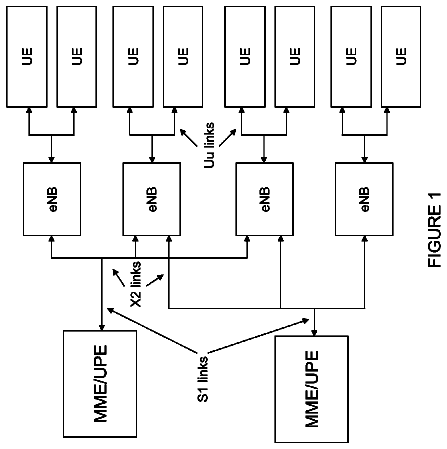
FIG. 1 illustrates a prior art MIMO system.
FIG. 2 illustrates an N-antenna Base Station communicating with a plurality of Single-antenna Client Devices.
FIG. 3 illustrates a three Antenna Base Station communicating with three Single-Antenna Client Devices
FIG. 4 illustrates training signal techniques employed in one embodiment of the invention.
FIG. 5 illustrates channel characterization data transmitted from a client device to a base station according to one embodiment of the invention.
FIG. 6 illustrates a Multiple-Input Distributed-Output ("MIDO") downstream transmission according to one embodiment of the invention.
FIG. 7 illustrates a Multiple-Input Multiple Output ("MIMO") upstream transmission according to one embodiment of the invention.
FIG. 8 illustrates a base station cycling through different client groups to allocate throughput according to one embodiment of the invention.
FIG. 9 illustrates a grouping of clients based on proximity according to one embodiment of the invention.
FIG. 10 illustrates an embodiment of the invention employed within an NVIS system.
FIG. 11 illustrates an embodiment of the DIDO transmitter with I/Q compensation functional units.
FIG. 12 a DIDO receiver with I/Q compensation functional units.
FIG. 13 illustrates one embodiment of DIDO-OFDM systems with I/Q compensation.
FIG. 14 illustrates one embodiment of DIDO 2.times.2 performance with and without I/Q compensation.
FIG. 15 illustrates one embodiment of DIDO 2.times.2 performance with and without I/Q compensation.
FIG. 16 illustrates one embodiment of the SER (Symbol Error Rate) with and without I/Q compensation for different QAM constellations.
FIG. 17 illustrates one embodiment of DIDO 2.times.2 performances with and without compensation in different user device locations.
FIG. 18 illustrates one embodiment of the SER with and without I/Q compensation in ideal (i.i.d. (independent and identically-distributed)) channels.
FIG. 19 illustrates one embodiment of a transmitter framework of adaptive DIDO systems.
FIG. 20 illustrates one embodiment of a receiver framework of adaptive DIDO systems.
FIG. 21 illustrates one embodiment of a method of adaptive DIDO-OFDM.
FIG. 22 illustrates one embodiment of the antenna layout for DIDO measurements.
FIG. 23 illustrates embodiments of array configurations for different order DIDO systems.
FIG. 24 illustrates the performance of different order DIDO systems.
FIG. 25 illustrates one embodiment of the antenna layout for DIDO measurements.
FIG. 26 illustrates one embodiment of the DIDO 2.times.2 performance with 4-QAM and FEC rate 1/2 as function of the user device location.
FIG. 27 illustrates one embodiment of the antenna layout for DIDO measurements.
FIG. 28 illustrates how, in one embodiment, DIDO 8.times.8 yields larger SE than DIDO 2.times.2 for lower TX power requirement.
FIG. 29 illustrates one embodiment of DIDO 2.times.2 performance with antenna selection.
FIG. 30 illustrates average bit error rate (BER) performance of different DIDO precoding schemes in i.i.d. channels.
FIG. 31 illustrates the signal to noise ratio (SNR) gain of ASel as a function of the number of extra transmit antennas in i.i.d. channels.
FIG. 32 illustrates the SNR thresholds as a function of the number of users (M) for block diagnalization (BD) and ASel with 1 and 2 extra antennas in i.i.d. channels.
FIG. 33 illustrates the BER versus per-user average SNR for two users located at the same angular direction with different values of Angle Spread (AS).
FIG. 34 illustrates similar results as FIG. 33, but with higher angular separation between the users.
FIG. 35 plots the SNR thresholds as a function of the AS for different values of the mean angles of arrival (AOAs) of the users.
FIG. 36 illustrates the SNR threshold for an exemplary case of five users.
FIG. 37 provides a comparison of the SNR threshold of BD and ASel, with 1 and 2 extra antennas, for two user case.
FIG. 38 illustrates similar results as FIG. 37, but for a five user case.
FIG. 39 illustrates the SNR thresholds for a BD scheme with different values of AS.
FIG. 40 illustrates the SNR thresholds in spatially correlated channels with AS=0.1.degree. for BD and ASel with 1 and 2 extra antennas.
FIG. 41 illustrates the computation of the SNR thresholds for two more channel scenarios with AS=5.degree..
FIG. 42 illustrates the computation of the SNR thresholds for two more channel scenarios with AS=10.degree..
FIGS. 43-44 illustrate the SNR thresholds as a function of the number of users (M) and angle spread (AS) for BD and ASel schemes, with 1 and 2 extra antennas, respectively.
FIG. 45 illustrates a receiver equipped with frequency offset estimator/compensator.
FIG. 46 illustrates DIDO 2.times.2 system model according to one embodiment of the invention.
FIG. 47 illustrates a method according to one embodiment of the invention.
FIG. 48 illustrates SER results of DIDO 2.times.2 systems with and without frequency offset.
FIG. 49 compares the performance of different DIDO schemes in terms of SNR thresholds.
FIG. 50 compares the amount of overhead required for different embodiments of methods.
FIG. 51 illustrates a simulation with a small frequency offset of f.sub.max=2 Hz and no integer offset correction.
FIG. 52 illustrates results when turning off the integer offset estimator.
FIG. 53 illustrates downlink spectral efficiency (SE) in [bps/Hz] as a function of mutual information in [bps/Hz].
FIG. 54 illustrates average per-user symbol error rare (SER) performance as a function of the mutual information in [bps/Hz].
FIG. 55 illustrates average per-user SER performance as a function of the minimum mutual information in [bps/Hz] and the thresholds used to switch between different DIDO modes.
FIG. 56 illustrates average per-user SER vs. SNR for fixed modulation and adaptive DIDO systems.
FIG. 57 illustrates downlink SE vs. SNR for fixed modulation and adaptive DIDO systems.
FIG. 58 illustrates average per-user SER vs. SNR for adaptive DIDO systems with different thresholds.
FIG. 59 illustrates downlink SE vs. SNR for adaptive DIDO systems with different thresholds
FIG. 60 illustrates average per-user SER performance as a function of the minimum singular value of the effective channel matrix and the CQI threshold for 4-QAM constellation.
FIG. 61 illustrates one embodiment of a circular topology of base transceiver stations (DIDO antennas)
FIG. 62 illustrates an one embodiment of an alternate arrangement of DIDO antennas.
FIG. 63 illustrates one embodiment in which a base station network (BSN) is used to deliver precoded baseband data from the centralized processors (CPs) to DIDO antennas.
FIG. 64 illustrates one embodiment in which the BSN is used to carry modulated signals.
FIG. 65 illustrates one embodiment comprised of two DIDO base stations perfectly synchronized and two users with Line Of Sight (LOS) channels
FIG. 66 illustrates the path loss of DIDO at 85 MHz and 400 MHz using the Hata-Okumura model.
FIG. 67 illustrates the period maximum delay between channel state information and data transmission as a function of the relative velocity between transmitter and receiver for different frequencies in the UHF band.
FIG. 68 illustrates propagation effects in DIDO systems for three different carrier frequencies.
FIG. 69 illustrates the areas in the US territory currently covered by transceiver stations operating in the Maritime band. The colors identify the number of active channels (out of the 146 channels available in the Maritime band) that would cause harmful interference to DIDO-NVIS stations at any location.
FIG. 70 illustrates sunspot number from the January 1900 throughout June 2009.
FIG. 71 illustrates the path loss of WiMAX, LTE and NVIS systems.
FIG. 72 illustrates the locations of DIDO-NVIS transmitter (TX) and receiver (RX) stations
FIG. 73 illustrates DIDO-NVIS receive antenna location. "lambda" denotes the wavelength at 3.9 MHz (.about.77 meters)
FIG. 74 illustrates typical 4-QAM constellations demodulated at three users' locations over DIDO-NVIS links.
FIG. 75 illustrates SER as a function of PU-SNR for DIDO-NVIS 3.times.3.
FIG. 76 illustrates DIDO-NVIS cells across the territory of the 48 contiguous states of the USA.
FIG. 77 illustrates a main DIDO cluster surrounded by neighboring DIDO clusters in one embodiment of the invention.
FIG. 78 illustrates frequency division multiple access (FDMA) techniques employed in one embodiment of the invention.
FIG. 79 illustrates time division multiple access (TDMA) techniques employed in one embodiment of the invention.
FIG. 80 illustrates different types of interfering zones addressed in one embodiment of the invention.
FIG. 81 illustrates a framework employed in one embodiment of the invention.
FIG. 82 illustrates a graph showing SER as a function of the SNR, assuming SIR=10 dB for the target client in the interfering zone.
FIG. 83 illustrates a graph showing SER derived from two IDCI-precoding techniques.
FIG. 84 illustrates an exemplary scenario in which a target client moves from a main DIDO cluster to an interfering cluster.
FIG. 85 illustrates the signal-to-interference-plus-noise ratio (SINR) as a function of distance (D).
FIG. 86 illustrates the symbol error rate (SER) performance of the three scenarios for 4-QAM modulation in flat-fading narrowband channels.
FIG. 87 illustrates a method for IDCI precoding according to one embodiment of the invention.
FIG. 88 illustrates the SINR variation in one embodiment as a function of the client's distance from the center of main DIDO clusters.
FIG. 89 illustrates one embodiment in which the SER is derived for 4-QAM modulation.
FIG. 90 illustrates one embodiment of the invention in which a finite state machine implements a handoff algorithm.
FIG. 91 illustrates depicts one embodiment of a handoff strategy in the presence of shadowing.
FIG. 92 illustrates a the hysteresis loop mechanism when switching between any two states in FIG. 93.
FIG. 93 illustrates one embodiment of a DIDO system with power control.
FIG. 94 illustrates the SER versus SNR assuming four DIDO transmit antennas and four clients in different scenarios.
FIG. 95 illustrates MPE power density as a function of distance from the source of RF radiation for different values of transmit power according to one embodiment of the invention.
FIG. 96a-b illustrate different distributions of low-power and high-power DIDO distributed antennas.
FIG. 97a-b illustrate two power distributions corresponding to the configurations in FIGS. 96a and 96b, respectively.
FIG. 98a-b illustrate the rate distribution for the two scenarios shown in FIGS. 99a and 99b, respectively.
FIG. 99 illustrates one embodiment of a DIDO system with power control.
FIG. 100 illustrates one embodiment of a method which iterates across all antenna groups according to Round-Robin scheduling policy for transmitting data.
FIG. 101 illustrates a comparison of the uncoded SER performance of power control with antenna grouping against conventional eigenmode selection in U.S. Pat. No. 7,636,381.
FIGS. 102a-c illustrate the scenarios in which BD precoding dynamically adjusts the precoding weights to account for different power levels over the wireless links between DIDO antennas and clients.
FIG. 103 illustrates the amplitude of low frequency selective channels (assuming .beta.=1) over delay domain or instantaneous PDP (upper plot) and frequency domain (lower plot) for DIDO 2.times.2 systems
FIG. 104 illustrates one embodiment of a channel matrix frequency response for DIDO 2.times.2, with a single antenna per client.
FIG. 105 illustrates one embodiment of a channel matrix frequency response for DIDO 2.times.2, with a single antenna per client for channels characterized by high frequency selectivity (e.g., with .beta.=0.1).
FIG. 106 illustrates exemplary SER for different QAM schemes (i.e., 4-QAM, 16-QAM, 64-QAM).
FIG. 107 illustrates one embodiment of a method for implementing link adaptation (LA) techniques.
FIG. 108 illustrates SER performance of one embodiment of the link adaptation (LA) techniques.
FIG. 109 illustrates the entries of the matrix in equation
as a function of the OFDM tone index for DIDO 2.times.2 systems with N.sub.FFT=64 and L.sub.0=8.
FIG. 110 illustrates the SER versus SNR for L.sub.0=8, M=N.sub.t=2 transmit antennas and a variable number of P.
FIG. 111 illustrates the SER performance of one embodiment of an interpolation method for different DIDO orders and L.sub.0=16.
Detailed description
One solution to overcome many of the above prior art limitations is an embodiment of Distributed-Input Distributed-Output (DIDO) technology. DIDO technology is described in the following patents and patent applications, all of which are assigned the assignee of the present patent and are incorporated by reference. These patents and applications are sometimes referred to collectively herein as the "related patents and applications":
U.S. application Ser. No. 12/630,627, filed Dec. 2, 2009, entitled "System and Method For Distributed Antenna Wireless Communications"
U.S. Pat. No. 7,599,420, filed Aug. 20, 2007, issued Oct. 6, 2009, entitled "System and Method for Distributed Input Distributed Output Wireless Communication";
U.S. Pat. No. 7,633,994, filed Aug. 20, 2007, issued Dec. 15, 2009, entitled "System and Method for Distributed Input Distributed Output Wireless Communication";
U.S. Pat. No. 7,636,381, filed Aug. 20, 2007, issued Dec. 22, 2009, entitled "System and Method for Distributed Input Distributed Output Wireless Communication";
U.S. application Ser. No. 12/143,503, filed Jun. 20, 2008 entitled, "System and Method For Distributed Input-Distributed Output Wireless Communications";
U.S. application Ser. No. 11/256,478, filed Oct. 21, 2005 entitled "System and Method For Spatial-Multiplexed Tropospheric Scatter Communications";
U.S. Pat. No. 7,418,053, filed Jul. 30, 2004, issued Aug. 26, 2008, entitled "System and Method for Distributed Input Distributed Output Wireless Communication";
U.S. application Ser. No. 10/817,731, filed Apr. 2, 2004 entitled "System and Method For Enhancing Near Vertical Incidence Skywave ("NVIS") Communication Using Space-Time Coding.
For organization purposes, the present detailed description is separated into the following sections:
I. Disclosure of the Present Application which includes new matter introduced in the present application and includes FIGS. 80-111 and associated text;
II. Disclosure From Certain Related Applications which includes matter previously disclosed in certain related applications and which includes FIGS. 1-60 and associated text; and
III. Disclosure From U.S. application Ser. No. 12/630,627 which includes new matter introduced in the most recent related application in this series (having Ser. No. 12/630,627) and which includes FIGS. 61-79 and associated text.
Note that section I (Disclosure of the Present Application) utilizes its own set of endnotes which refer to prior art references and prior applications assigned to the assignee of the present application. The endnote citations are listed at the end of section I (just prior to the heading for Section II). Citations in Sections II and III may have numerical designations which overlap with those used in Section I even through these numerical designations identify different references (which are identified within each respective section). Thus, references identified by a particular numerical designation may be identified within the section in which the numerical designation is used.
I. Disclosure of the Present Application
1. Methods to Remove Inter-Cluster Interference
The description continues in the full USPTO document.
 Lapsed, fee not paid4 drawings