Field of the invention
The present invention generally relates to advanced medical endoluminal devices for, and methods of, minimally invasive treatment of blockages of the blood vessels and other tubular organs. More particularly, the present invention relates to self-expanding stents for internal reinforcing of diseased tubular structure and/or for local delivery of pharmacological or radioactive agents having a beneficial advantage of repositioning or retrieval.
Background of the invention
A stent is a generally longitudinal cylindrical device formed of biocompatible material, such as a metal or plastic, which is used in the treatment of stenosis, strictures, or aneurysms in body blood vessels and other tubular body structures, such as the esophagus, bile ducts, urinary tract, intestines or tracheo-bronchial tree. References hereafter to "blood vessels" and "vessels" will be understood to refer to all such tubular body structures. A stent is held in a reduced diameter state during its passage through a low profile catheter until delivered to the desired location in the blood vessel, whereupon the stent radially expands to an expanded diameter state in the larger diameter vessel to hold the vessel open. As discussed below, radial expansion of the stent may be accomplished by an inflatable balloon attached to a catheter, or the stent may be of the self-expanding type that will radially expand once deployed from the end portion of a delivery catheter.
Stented vessels have a tendency to develop aggressive intimal hyperplasia. Intimal hyperplasia is part of the endothelialization process by which the stent becomes incorporated into the vessel wall as a result of the vessel's reaction to a foreign body, and is characterized by deposition of cell layers covering the stent. It eventually results in formation of a neointima, which coats the stent and buries it completely in the vessel wall.
Endothelialization generally improves patency rates and the more complete the apposition of the stent to the vessel wall, the more uniform and optimal is the degree of endothelialization. Of course, a fundamental concern is that the stent be deployed in the correct desired location in the vessel as precisely as possible in the first place. This is important when delivering radiation or medication to a particular location using the stent.
Stents fall into one of two categories based on their mechanism of deployment and radial expansion, namely, balloon-expandable stents and self-expanding stents.
Balloon-expandable stents (BES) are mounted in their reduced diameter state on nylon or polyethylene balloons, usually by manual crimping, while others are available pre-mounted. One example of a BES is shown in U.S. Pat. No. 4,733,665 to Palmaz. BES rely solely on balloon dilation to attain the desired expanded configuration or state. This enables BES to be deployed in a relatively controlled gradual manner. BES in general have more strength than self-expanding stents and initially resist deformation as well as recoil. BES behave elastically but eventually yield and become irreversibly, i.e. plastically, deformed under external force. Most BES are less flexible than self-expanding stents and are therefore less capable of being delivered through tortuous vessels and, when a BES is deployed in a tortuous vessel, it often straightens the vessel, forcing the vessel to conform to the shape of the stent rather than vice versa. This generally results in portions of the stent not being completely apposed to the vessel wall which in turn affects endothelialization and overall patency rate.
On the other hand, BES can generally be deployed in a relatively precise manner at the correct desired location in the vessel since they can be deployed in a controlled gradual manner by gradually controlling the inflation of the balloon. This ability to gradually control the expansion of the stent, along with the fact that BES rarely change their position on the balloon during inflation, enable fine adjustments to be made by the operator in the position of the stent within the vessel prior to stent deployment.
Self-expanding stents (SES) are formed of braided stainless steel wire or shape-memory alloy such as nitinol and are generally delivered to desired locations in the body in a reduced diameter state in a low profile catheter while covered by an outer sheath which partially insulates the SES from body temperature and mechanically restrains them.
Nitinol is an alloy comprised of approximately 50% nickel and 50% titanium. Nitinol has properties of superelasticity and shape memory. Superelasticity refers to the enhanced ability of material to be deformed without irreversible change in shape. Shape memory is the ability of a material to regain its shape after deformation at a lower temperature. These physical properties of nitinol allow complex device configurations and high expansion ratios enabling percutaneous delivery through low profile access systems.
Superelasticity and shape memory are based on nitinol's ability to exist in two distinctly different, reversible crystal phases in its solid state at clinically useful temperatures. The alignment of crystals at the higher temperature is called the austenite (A) phase; the alignment of crystals at the lower temperature is called the martensite (M) phase. In between is a temperature interval of gradual transition between the A and M phases.
Under external force, the shape of a nitinol device can be greatly deformed without irreversible damage. Depending on the temperature at which this external force is applied, superelastic or shape memory effects prevail. In close vicinity to or above the temperature defining transition into the full A state, superelasticity results: as soon as the deforming force is released, the device immediately assumes it original shape. When nitinol is deformed at or below the lower temperature of the complete M transition, the shape memory effect can be exploited. The device retains its deformed shape even after the external force is removed as long as the temperature of the environment stays below the temperature of transition into A phase. Only during heating does the device resume its original shape.
While the shape memory effect is essentially a one-way type phenomena in which shape recovery occurs only upon heating the alloy to a temperature defining transition to the full A phase, by subjecting the alloy itself to a biasing force, i.e. an internal stress formed by dislocations introduced by plastic deformation in the alloy, a two-way shape memory can be imparted to the alloy so that cooling the alloy will induce a shape change.
One type of self-expanding stent is constructed of wire formed of a shape-memory alloy, such as nitinol, having a transition temperature of about body temperature, i.e. 37.degree. C. For example, reference is made to U.S. Pat. No. 5,746,765 to Kleshinski et al. The one-way transition temperature is the temperature of transformation of a nitinol device from its collapsed state into a fully expanded configuration. The stent is pre-loaded on a low profile catheter by crimping the stent at room temperature (at which it can be plastically deformed) onto the catheter. An outer sheath covers the crimped stent and at least partially thermally insulates the stent as it is delivered to the desired location. Upon reaching the desired location, the sheath is withdrawn and the stent is exposed to body temperature whereupon it is naturally warmed to body temperature and expands to its expanded diameter state in supporting contact with the vessel wall. In a fully expanded state within the human body, the stent is capable of exerting considerable radial force on the surrounding structures, which allows mechanical opening of the vessel lumen and maintaining its long-term patentcy for free passage of flow.
If an alloy is used for which shape recovery occurs above body temperature, the SES must be heated after release into the body. If shape recovery occurs below body temperature, the device may be cooled during the delivery to prevent expansion inside the delivery catheter. If shape recovery occurs at body temperature, no heating or cooling is necessary during the delivery and deployment, provided delivery is relatively speedy. If, however, a tortuous iliac anatomy or other interference delays prompt deployment of a nitinol stent with these characteristics, premature warming to body temperature could cause expansion in the delivery sheath, increase friction, and interfere with delivery. In this instance, flushing with a cool solution has been suggested.
SES do not require any special preparation prior to deployment. SES behave elastically throughout their lifetime, and do not become irreversibly deformed. When deployed, the nominal diameter is purposely selected to be greater that the diameter of the vessel. Therefore, once deployed, an SES exerts continuous outward force on the vessel as it tries to expand to its original dimensions. The ability of an SES to continuously exert an outward force on the vessel coupled with the greater flexibility of SES, generally results in optimal wall apposition, thereby optimizing endothelialization and improving patency rates. Nitinol self-expanding stents have been designed having good radial and hoop strength.
However, while SES are preferable relative to BES in many applications with respect to achieving optimized endothelialization and increased patency rates, currently available arrangements of SES are not entirely satisfactory. It has generally not been possible to deploy SES in the correct desired location in a vessel as precisely as in the case of BES with currently available delivery arrangements for the reason that the temperature of the SES rapidly increases to body temperature upon withdrawal of the outer sheath and therefore the stent quickly expands into engagement with the vessel wall. Consequently, there is not always enough time to finely adjust the position of the SES as it quickly expands, and it is not uncommon for the distal end of an SES, which is exposed to body temperature first, and which therefore expands before the rest of the SES, to engage and become attached to the vessel wall in the wrong position and in turn inhibit or prevent further adjustments in the position of the SES in the vessel.
Still another drawback in conventional arrangements for delivering and deploying SES is the possibility that when delivery is protracted, the SES is exposed to body temperature inside the delivery system. The deployment process can then become more difficult--the device may open abruptly after being freed from the system and may "jump" beyond the target as the SES expands during deployment. BES cannot be repositioned or retrieved after deployment and while arrangements have been proposed for enabling the repositioning and/or retrieval of SES formed of two-way shape memory material, no practical workable arrangement has been developed.
A malpositioned stent often requires an additional stent placement to correct the mistake and achieve the desired results. The stents will remain in the vessel for the entire life of the patient. In a high percentage of patients, the stent will become the site of recurrent stenosis due to an aggressive neointimal proliferation. These patients require repeated interventions, which often include balloon angioplasty and/or additional stent placement.
The most striking illustration of these problems is seen in cardiac patients. Stents and balloon angioplasty transformed the care of patients with heart disease. Each year, about 700,000 patients in the U.S. undergo angioplasty, in which a balloon is used to clear an obstruction in a coronary artery and a stent is deployed to keep it open. Yet a disturbingly high 15% to 20% of the procedures fail within six months, due to the aggressive neointimal proliferation. These patients will often undergo further major treatments, which might be repeated several times.
The need to be able to reposition and/or retrieve stents from a vessel also arises from the fact that a new generation of stents has been developed, that not only prop open the vessel, but which deliver drugs to the site of the blockage in an effort to minimize or eliminate neointimal proliferation and keep the vessel open for long periods of time. Studies have shown that stents coated with a drug called rapamycin, essentially eliminate re-stenosis. Other medications, such as nitric oxide and paclitaxel or similar compounds, also have a potential to prevent proliferation of scar tissue by killing such cells. One concern is whether the drugs might work too well, inhibiting not only re-stenosis, but also the necessary growth of the thin layer of neointima. As previously described, this thin layer of cells, which grows over the stent, smoothes its surface (similar to a layer of Teflon), so blood cells can flow over it without damaging themselves. A damaged blood cell initiates a chemical cascade, which results in clot formation. Therefore an exposed bare metallic stent carries a risk of inducing thrombus formation within it.
The potential of radioactive stents to prevent re-stenosis is an additional area of active development, since local radiation has been shown to inhibit the growth of neointima and halt the progression of atherosclerotic disease.
One can therefore appreciate the benefit of being able to retrieve a stent used for local drug delivery or radiation treatment, after it has achieved its desired effect. This would eliminate potential risk of thrombus formation at the site of the exposed bare stent.
In summary, ideally an optimal stent should possess and combine all the positive traits mentioned so far in each of the stent categories. The stent should be pre-loaded on the delivery apparatus and should not require special preparation. It should be flexible to enhance apposition to the vessel wall. It should provide a controlled gradual deployment without stent migration to ensure deployment of the stent in the correct location. Lastly, in case of a malpositioned stent, or stent which is deployed for the purpose of its temporary effect, such as for local drug delivery, the stent should have the option of enabling repositioning and/or retrieval.
SES can be preloaded on the delivery apparatus, do not require special preparation and are flexible. However, to date, no satisfactory system is available for repositioning and/or retrieving a SES. While arrangements have been suggested in the prior art for repositioning and retrieving SES formed of two-way shape memory material, these prior art arrangements all have drawbacks and have not been adopted in practice.
An arrangement for delivering, repositioning and/or retrieving an SES formed of a two-way shape memory alloy capable of expansion or collapsing in the radial direction in accordance with changes in temperature is disclosed in U.S. Pat. No. 5,037,427 to Harada et al. According to Harada et al., a stent is made of nitinol alloy trained to have two-way shape memory. The stent is in an expanded diameter state at about body temperature and in a reduced diameter state at a temperature below body temperature. In delivering the stent, the stent is mounted in the reduced diameter state at the distal end of a catheter over a portion of the catheter having a number of side ports. Cooling water supplied through the catheter flows out from the side hole and is brought into contact with the stent during delivery to maintain the stent below body temperature and therefore in the reduced diameter state. When the SES is positioned at the desired location, the supply of the cooling water is stopped and the stent is warmed by the heat of the body and expands into supporting engagement with the wall of the vessel. The catheter is then withdrawn. In retrieving an already-positioned SES using this system, the distal end portion of the catheter is inserted into the expanded stent lumen and a cooling fluid is introduced into the catheter and discharged through the side ports at the distal end region into the vessel whereupon the stent is cooled and purportedly collapses onto the distal end portion of the catheter. The stent is retrieved by withdrawing the catheter. The patent suggests that the position of the stent can also be changed using this technique.
U.S. Pat. No. 5,746,765 to Kleshinski, Simon, and Rabkin also discloses a stent made from an alloy with two-way shape memory, which expands inside the vessel due to natural heating to body temperature. The stent is covered with an elastic sleeve. When the metal frame is softened by decreased temperature, the sleeve overcomes its radial force and promotes its further contraction for easier retrieval.
However, in both the arrangements disclosed in Harada et al. and Kleshinski et al., a substantial amount of very cold solution must be infused into the vessel in order to reduce the local temperature of the environment surrounding the stent. Cold temperature around the stent must be maintained for some time until the stent is delivered or recovered for retrieval or repositioning. This technique appears to be clinically impractical and not safe due to high risk of potential tissue and blood cell damage.
U.S. Pat. No. 6,077,298 to Tu et al. discloses a retractable stent made from a one-way shape-memory alloy, such as nitinol, that can be deployed into the body by means of dilation with a balloon catheter. For the stent retrieval, a radio frequency current within the range of 50 to 2,000 kHz must be applied directly to the stent to provide partial collapse of the stent after it is heated to a temperature above 43.degree. C. to 90.degree. C. However, if the transition temperature of the stent material is in the range of 43.degree. C.-90.degree. C., the radial force of the device will be greatly reduced at the body temperature of 37.degree. C., and may not be sufficient for therapeutic effect. Heating of the stent to almost a boiling temperature can cause irreversible damage to vascular wall and blood coagulation.
U.S. Pat. No. 5,961,547 to Razavi, U.S. Pat. No. 5,716,410 to Wang et al., U.S. Pat. No. 5,449,372 to Schwaltz et al. and U.S. Pat. No. 5,411,549 to Peters disclose temporary or retractable stents in the shape of a spiral coil or a double helix. Although these stents are made of different materials, such as metal or plastic, and have differences in the techniques of their deployment (heat-activated, self-expanding or balloon expandable), as well as methods of their retrieval (mechanical straightening vs. softening by increasing temperature vs. latch retraction), all of them have one common feature. The stents are connected with a wire extending outside the patient at all times and when they have to be removed, they are simply retracted back into the catheter with or without prior softening of the material. For this reason these stents cannot be left in the human body for more than a couple of days. The connecting wire can traverse the entire body if the stent is placed in the coronary or carotid artery from the femoral approach, increasing risk of thrombus formation around the wire and distal embolization, thrombosis of the femoral artery and infection of the inquinal region.
U.S. Pat. No. 5,941,895 to Myler et al. discloses a removable cardiovascular stent with engagement hooks extending perpendicular to the axis of the stent into the vessel lumen. The stent retrieval technique requires introduction of an extraction catheter, which is adapted to grasp the engagement hooks of the stent with subsequent stent elongation in axial direction and reduction of its cross-sectional diameter. However, the stent with inwardly extending engagement members will likely require a larger delivery system than regular tubular devices. Any manipulation of the catheters and guidewires in the stented area may potentially accidentally engage the hooks of the stent with its subsequent dislodgment and damage of, the vessel. The hooks extending into the vessel lumen will cause turbulence of blood flow around them, leading to activation of the coagulation system and thrombus formation.
U.S. Pat. No. 5,833,707 to McIntyre et al. discloses a stent formed from a thin sheet of metal that has been wound around itself into a general cylindrical tight roll and expands inside the body by heating to body temperature. This stent is designed for predominant use in the human urethra and is not suitable for cardiovascular applications due to very large metal surface that could be thrombogenic and increased size of the delivery system. The stent can be removed from the body with the help of a cannula or pincer grips for grasping the edge of the stent. By rotating the pinched stent, the pincer or cannula cause the stent to telescopically coil into smaller diameter, which can then be retrieved from the urethra. This technique could be too traumatic for cardiovascular applications. The recovery apparatus will likely have a large profile, making this method not practical or feasible for percutaneous use in blood vessels or other tubular organs.
U.S. Pat. No. 5,562,641 to Flomenblit et al. discloses a spiral or cylindrical stent made from alloy with two-way shape memory capabilities. The stent expands inside the body by heating to the temperature of 50.degree. C. to 80.degree. C. with an electric current, injection of hot fluid, external radio frequency irradiation or use of radio frequency antenna inside the catheter. The stent can be removed from the body after cooling to a temperature, ranging from -10.degree. C. to +20.degree. C., at which the stent partially collapses in diameter and can be grasped with a catheter for retrieval. As discussed above, heating of the stent to a temperature over 80.degree. C. could be unsafe, especially with intravascular injection of hot fluid. Use of external radio frequency irradiation will cause heating not only of the stent, but all tissues from the skin surface to the stented vessel deep inside the body and beyond. Cooling the stent to below the freezing temperature by injection of a very cold fluid into a blood circulation for removal is also impractical and not feasible in a real clinical setting.
Summary of the invention
Accordingly, it is an object of the present invention to provide a new and improved stent device for reinforcing blood vessels and other tubular body structures, that can be used temporarily to keep the vessels open.
Another object of the present invention is to provide a new and improved stent device, that can be repositioned after complete deployment using endovascular techniques.
Still another object of the present invention is to provide a new and improved stent device, that can be removed from the body completely after being implanted for a certain period of time using endovascular techniques.
Briefly, in accordance with one aspect of the present invention, these and other objects are attained by providing a specially constructed self-expanding stent formed of a shape memory alloy, such as Nitinol, which exhibits or is trained to have a second way memory, and can be partially or completely collapsed from its fully expanded condition by means of engaging with a thermal transfer device coupled to a catheter assembly. The stent has a configuration designed to interact with a retrieval device coupled to the catheter assembly which captures and holds the stent during repositioning and/or retrieval.
Thermal transfer devices and retrieval devices are preferably of the type disclosed in applicants' pending applications: Ser. Nos. 09/845,090 and 09/845,098, both filed Apr. 27, 2001 and assigned to the assignee of the instant application. The disclosures of these applications (hereinafter, the "prior applications") are incorporated herein in their entirety.
The thermal transfer device disclosed in the prior applications is constructed such that the temperature of the stent can be controlled quickly, precisely and non-invasively. Specifically, the temperature of the stent can be changed quickly by placing it in local heat transfer relationship with a thermal transfer device attached to the end of a catheter assembly. For present purposes, "local heat transfer relationship" means either the stent contacts the thermal device or the stent and thermal transfer device are sufficiently close, so that heat is transferred between the stent and the thermal transfer device without materially affecting the temperature of the surrounding tissue. The stent's temperature can be controlled relatively precisely since the stent has a low mass so that the temperature of the stent will essentially correspond to the temperature of the thermal transfer device, which has a much higher mass. Moreover, no liquid or gas will be infused into the vessel during the entire procedure.
This feature makes the arrangement particularly adapted for repositioning and/or retrieving stents formed of two-way shape memory alloys that have already been deployed in a vessel, such as in the repositioning of a misplaced stent, removal of a stent placed for temporary indications, or the removal of a stent that has completed the delivery of medication or radiation to a particular area. Specifically, for removal and/or repositioning of the stent, the thermal transfer device is structured and arranged to be initially positioned in the lumen of the already deployed stent in a collapsed condition, out of contact or other local heat transfer relationship with the deployed stent, and then expanded into contact, or other local heat transfer relationship with the stent. The temperature of the heat transfer device is adjusted so that the temperature of the deployed stent is reduced to that at which the stent obtains a relaxed, flexible state whereupon it separates from the vessel wall. The stent can then be engaged by capturing hooks attached to the catheter assembly and drawn into the catheter assembly and either removed from the body or repositioned using the initial delivery process described above.
The stent is constructed such that it is easily engaged by the capturing hooks forming part of the retrieval device coupled to the catheter assembly for purposes of retrieval and/or repositioning. This arrangement prevents the stent from being carried away by the bloodstream or from migrating on the catheter. The retrieval device is also structured and arranged to assist in drawing the stent in its flexible and pliable condition into the catheter assembly for repositioning and retrieval.
One advantageous aspect of the present invention is that the stent is formed of two main components, namely, a stent body and a specially constructed stent crown provided at one or both ends of the stent body. The crown is preferably imparted with a greater two-way memory than the rest of the stent. The two-way shape memory and construction of the crown facilitate repositioning and/or removal of the stent. The actual repositioning and/or retrieval, can be performed immediately after stent deployment, during the same procedure or weeks later, depending on the clinical situation, the exact purpose of the stent and its applications.
Another advantageous aspect of the present invention is the particular geometry of the annular rings defining each respective functional segment of the stent, with or without the crown, and the relative strength of the two-way memory imparted to that segment to provide advantageous flexibility, radial force and two-way memory effect for each segment to thereby provide a stent which is not difficult to position, which is effective in operation, and which can be repositioned and/or retrieved using the techniques disclosed in the prior applications.
Description of the drawings
A more complete appreciation of the present invention and many of the attendant advantages thereof will be readily understood by reference to the following detailed description when considered in connection with the accompanying drawings in which:
FIG. 1 is a front elevation view of one embodiment of a retrievable/repositionable stent according to the invention shown in its expanded configuration;
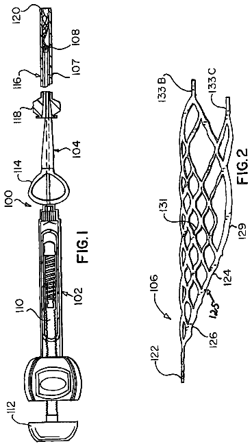
FIG. 2 shows a laser-slotted tube constituting the stent shown in FIG. 1 in an unexpanded configuration, cut longitudinally and flattened;
FIG. 3 is a schematic view of the stent shown in FIG. 1 in its expanded configuration, cut longitudinally and flattened;
FIG. 4(a) is a schematic perspective view of another embodiment of a stent in accordance with the invention in the process of manufacture, after expansion, but before a second cut;
FIG. 4(b) is a schematic perspective view of the stent shown in FIG. 4(a) after a second cut;
FIG. 5 is a front elevation view of the stent shown in FIG. 1, after cooling with the crown leaves in their collapsed configuration and with a reduction in body diameter of the stent;
FIG. 6(a) is a front elevation view of another embodiment of a stent in accordance with the invention in its expanded configuration having a crown comprising leaves of equal lengths;
FIG. 6(b) is a front elevation view of the stent shown in FIG. 6(a) after cooling;
FIG. 7 shows a laser-slotted tube with crowns at each end, cut longitudinally and flattened;
FIGS. 8(a)-8(p) show different embodiments of stent crowns according to the invention;
FIG. 9 shows another embodiment of a stent in accordance with the present invention with the body of the stent formed solely of interconnected Z-rings, in an expanded configuration, cut longitudinally and flattened;
FIG. 10 shows another embodiment of a stent in accordance with the present invention with the body of the stent formed solely of interconnected closed-cell rings, in an expanded configuration, cut longitudinally and flattened;
FIG. 11 shows another embodiment of a stent in accordance with the present invention with the body of the stent formed of a combination of interconnected closed-cell rings and Z-rings, in an expanded configuration, cut longitudinally and flattened; and
FIGS. 12(a)-12(l) are twelve perspective views showing sequential steps of repositioning an already positioned stent.
Description of the preferred embodiments
Except where noted, stents to be retrieved and/or repositioned in accordance with the invention are formed of a shape memory material, as Nitinol, having or trained to have a second cold memory, i.e. a two-way shape memory material. When released into the vessel or other tubular structure and naturally warmed to first transition temperature at or below body temperature of 37.degree. C., the stent expands and recovers its previously imprinted intended functional shape at or below body temperature. In a fully expanded state within the human body, the stent is capable of exerting considerable radial force on the surrounding structures, which allows mechanical opening of the vessel lumen and maintaining its long-term patency for free passage of flow. When the fully expanded stent is cooled to a temperature in the range of -10.degree. C. to +35.degree. C., it becomes compliant, has a reduced stress state, and can be compressed into a reduced diameter, small enough to fit within a low profile delivery system for percutaneous retrieval and repositioning.
Stents according to the invention can be constructed of a single continuous thermal shape memory wire, or cut from a tube with laser technology, or formed with a photoetching technique from thermal shape memory tubing to create a mesh-like configuration.
Referring now to the drawings wherein like reference characters designate like or corresponding parts throughout the several views, a first embodiment of a stent in accordance with the invention, generally designated 10, is illustrated in FIGS. 1-3. Stent 10 comprises two main components: the body 12 and the crown 14 attached to the distal end of the stent body 12. It is understood that crowns may be provided at both ends of the stent body (see FIG. 7). The distal direction is towards the top of the drawing page.
Referring to FIGS. 1 and 3, the stent body 12 is formed of a plurality of interconnected annular closed-cell rings 16.sub.1, -16.sub.4 and Z-rings 18.sub.1, -18.sub.6. Each ring 16, 18 has a plurality, in this case twelve, of distal and proximal peaks Pp, Pd (see rings 16.sub.2 and 18.sub.1 in FIG. 1) and longitudinally adjacent rings (except for closed-cell rings 16.sub.2 and 16.sub.3) are interconnected at pairs of proximate opposed peaks. Closed-cell rings 16.sub.2 and 16.sub.3 are interconnected by shared walls. Generally, a closed-cell ring is formed by a pair of adjacent Z-rings interconnected at every, or at every other, pair of proximate opposed peaks. Reference is made to applicants' U.S. patent application Ser. No. 10/333,600 entitled Multi-Segment Modular Stent and Methods for Manufacturing Stents filed concurrently herewith, and the disclosure of which is incorporated herein in its entirety, with respect to the construction and characteristics of stents made from interconnected closed-cell rings and Z-rings. It is understood that the stent body may be formed with configurations other than shown in the illustrated embodiments.
Referring to FIG. 2, the mesh pattern of stent 10 is cut from a small diameter Nitinol tube 20 by a laser beam 20-80 microns thick. The diameter of Nitinol tube 20 is equal to the diameter of the stent 10 in its completely collapsed state. After cutting appropriate slots 21 in tube 20, the stent has to be gradually expanded to its final diameter, using special mandrels and cycles of annealing or heat treatment in the furnace at high temperatures. Certain designs of mesh patterns may require an additional second round of laser cutting or mechanical disruption after completion of the expansion of the stent.
Referring to FIGS. 1 and 3, the crown 14 of stent 10 is connected to the distal end of stent body 12 and specifically to the distal peaks P.sub.d of the end closed-cell ring 16.sub.1. Crown 14 comprises four elongated fingers or leaves 22.sub.1 22.sub.2, 22.sub.3 and 22.sub.4, each of which is formed by an outer arrowhead-shaped frame 24.sub.1, 24.sub.2, 24.sub.3, 24.sub.4 and an inner framework 26.sub.1, 26.sub.2, 26.sub.3, 26.sub.4, respectively. Each outer frame 24.sub.1-24.sub.4 in turn is formed by a pair of main struts 28.sub.1, 28.sub.1; 28.sub.2, 28.sub.2; 28.sub.3, 28.sub.3; 28.sub.4, 28.sub.4 that converge in the distal direction and meet at their distal ends at peaks 30.sub.1, 30.sub.2, 30.sub.3, 30.sub.4, and a pair of base struts 32.sub.1, 32.sub.1; 32.sub.2, 32.sub.2; 32.sub.3, 32.sub.3; 32.sub.4, 32.sub.4 that interconnect each pair of main struts 28 of a particular leaf to the distal peaks P.sub.d, of closed-cell ring 16. In this embodiment in which closed-cell ring 16.sub.1 defines twelve distal peaks, and there are four leaves 21.sub.1-21.sub.4, the base struts 32 of each leaf are connected to every third distal peak P.sub.d. Each of the inner frameworks 26.sub.1-26.sub.4 comprises a pair of angled support struts 34.sub.1, 34.sub.1; 34.sub.2, 34.sub.2; 34.sub.3, 34.sub.3; 34.sub.4, 34.sub.4 each of which has a distal end connected to a respective main strut 28.sub.1, 28.sub.1; 28.sub.2, 28.sub.2; 28.sub.3, 28.sub.3; 28.sub.4, 28.sub.4 and a proximal end connected to the distal peak of closed-cell ring 16.sub.1 adjacent to the peak to which the respective main strut is connected.
The main struts 28.sub.2, 28.sub.2 and 28.sub.4, 28.sub.4; of leaves 22.sub.2, 22.sub.4 are longer than main struts 28.sub.1, 28.sub.1 and 28.sub.3, 28.sub.3 of leaves 22.sub.1, 22.sub.3 and converge at shallower angles so that leaves 22.sub.2, and 22.sub.4, which are diametrically opposed to each other, are longer than diametrically opposed leaves 22.sub.1, 22.sub.3.
Referring to FIGS. 4A and 4B, a stent 110 is illustrated in FIG. 4B which is obtained from a slotted expanded tube 110a shown in FIG. 4A. Stent 110 includes a stent body 112 and a stent crown 114. Stent body 112 includes interconnected closed-cell rings 116.sub.1 and 116.sub.2 and Z-rings 118.sub.1-118.sub.8. Stent crown 114, like crown 14 of FIGS. 1-3, includes four leaves 122.sub.1-122.sub.4 including outer arrowhead-shaped frames 124.sub.1-124.sub.4, each of which includes pairs main struts 128.sub.1, 128.sub.1; 128.sub.2, 128.sub.2; 128.sub.3, 128.sub.3; 128.sub.4, 128.sub.4.
Stent 110 is shown in FIG. 4A in the process of manufacture. Specifically, a small diameter Nitinol tube has been laser cut and expanded to the configuration shown in FIG. 4A as 110a. This expansion is completed before laser cuts are made to form the base struts 132 of adjacent leaves connected to the same distal peaks P.sub.d of closed-cell ring 116.sub.1. Thus, during expansion and up to this stage of manufacture, struts 132.sub.1-2, 132.sub.2-3, 132.sub.3-4 and 132.sub.1-4 constitute four unitary structures. Moreover, the inner frameworks 126.sub.1-126.sub.4 are initially formed, and include during expansion and up to the stage of manufacture shown in FIG. 4A, temporary interconnector struts 136.sub.1-136.sub.4 interconnecting respective pairs of angled support struts 134.sub.1, 134.sub.1; 134.sub.2, 134.sub.2; 134.sub.3, 134.sub.3; 134.sub.4, 134.sub.4. By maintaining the base struts 132 of adjoining leaves in a unitary form and providing temporary interconnector struts 136 during the expansion and heat treatment of the small diameter tube, the desired shape and geometry of the leaves 122 of crown 114 is achieved uniformly in all four of the crown leaves 122.
Referring to FIG. 4B, when the desired configuration of the crown has been achieved, second laser cuts 136 are made to separate the originally unitary base struts of adjacent leaves, e.g. 132.sub.2-3, (FIG. 4A) into separate base struts 132.sub.2 and 132.sub.3 (FIG. 4B), and the temporary struts 136.sub.1-136.sub.4 are removed by laser or manually.
Alternatively, the mesh design of the stent can be laser cut from a large diameter tube, which is equal to the final diameter of a fully expanded stent. This technological process eliminates the need for cycles of expansion and heat treatments. However, these tubes are more expensive and there is a substantial amount of material wasted during the process of laser cutting. Also alternatively, the stent can be constructed from a shape memory wire and laser-welded at certain points to form the desired configuration. The stents are cut is in such manner that the width of the mesh struts is close or equal to the thickness of the wall of the original tube and fine tuned by postproccessing polishing techniques to provide a nearly round configuration in cross section.
The expansive force and the stiffness along the length of the stent can be modulated by changes in the dimensions of the cell geometry (see the attorney docket 471.1007 application). There are no open or sharp edges remaining at either end of the device. This prevents injury to the wall while improving the ability to position, reposition or retrieve the device. Because the struts never overlap, the stent wall thickness is never greater than the wire diameter and both surfaces are smooth. The cells of the stent create an open mesh, which is favorable for maintaining the patency of side branches, and also minimize the length differences between the collapsed and expanded forms of the stent. The shortening of the stent during its expansion depends on the cell geometry, but usually does not exceed 10% of the length of the stent in its completely expanded state. In a preferred embodiment, an intraluminal medical device may include a permanent or temporary implantable stent or stent-graft, a permanent or temporary device impregnated with medications or radioactivity for local therapy.
The description continues in the full USPTO document.
 Lapsed, fee not paid19 drawings