Field of the invention
The present invention relates to methods and apparatus for intraluminally forming and securing gastrointestinal ("GI") tissue folds. More particularly, the present invention relates to methods and apparatus for reducing the effective cross-sectional area of a gastrointestinal lumen.
Background
Morbid obesity is a serious medical condition pervasive in the United States and other countries. Its complications include hypertension, diabetes, coronary artery disease, stroke, congestive heart failure, multiple orthopedic problems and pulmonary insufficiency with markedly decreased life expectancy.
Several surgical techniques have been developed to treat morbid obesity, e.g., bypassing an absorptive surface of the small intestine, or reducing the stomach size. These procedures are difficult to perform in morbidly obese patients because it is often difficult to gain access to the digestive organs. In particular, the layers of fat encountered in morbidly obese patients make difficult direct exposure of the digestive organs with a wound retractor, and standard laparoscopic trocars may be of inadequate length.
In addition, previously known open surgical procedures may present numerous life-threatening post-operative complications, and may cause atypical diarrhea, electrolytic imbalance, unpredictable weight loss and reflux of nutritious chyme proximal to the site of the anastamosis. Further, the sutures or staples that are often used in these surgical procedures may require extensive training by the clinician to achieve competent use, and may concentrate significant force over a small surface area of the tissue, thereby potentially causing the suture or staple to tear through the tissue.
The gastrointestinal lumen includes four tissue layers, wherein the mucosa layer is the top tissue layer followed by connective tissue, the muscularis layer and the serosa layer. One problem with conventional gastrointestinal reduction systems is that the anchors (or staples) must engage at least the muscularis tissue layer in order to provide a proper foundation. In other words, the mucosa and connective tissue layers typically are not strong enough to sustain the tensile loads imposed by normal movement of the stomach wall during ingestion and processing of food. In particular, these layers tend to stretch elastically rather than firmly hold the anchors (or staples) in position, and accordingly, the more rigid muscularis and/or serosa layer must be engaged. This problem of capturing the muscularis or serosa layers becomes particularly acute where it is desired to place an anchor or other apparatus transesophageally rather than intraoperatively, since care must be taken in piercing the tough stomach wall not to inadvertently puncture adjacent tissue or organs.
In view of the aforementioned limitations, it would be desirable to provide methods and apparatus for forming gastrointestinal tissue folds that achieve gastric reduction by reconfiguring the GI lumen of a patient.
It would be desirable to provide methods and apparatus for forming gastrointestinal tissue folds using anchors that can be reconfigured from a reduced delivery profile to an expanded deployed profile.
It also would be desirable to provide methods and apparatus for forming gastrointestinal tissue folds, wherein an anchor assembly is extended across stomach folds that include the muscularis and serosa tissue layers.
It further would be desirable to provide methods and apparatus for forming gastrointestinal tissue folds, wherein the anchor assembly is deployed in a manner that reduces a possibility of injuring neighboring organs.
It still further would be desirable to provide methods and apparatus for forming gastrointestinal tissue folds, wherein reduced training of a clinician is required to achieve competent use of the anchor assembly.
Summary
In view of the foregoing, it is an object of the present invention to provide methods and apparatus for forming gastrointestinal tissue folds that achieve gastric reduction by reconfiguring the 81 lumen of a patient.
It is another object of the present invention to provide methods and apparatus for forming gastrointestinal tissue folds using anchors that can be reconfigured from a reduced delivery profile to an expanded deployed profile.
It is an additional object of this invention to provide methods and apparatus for forming gastrointestinal tissue folds in which an anchor assembly is extended across stomach folds that include the muscularis and serosa tissue layers.
It is a further object of the present invention to provide methods and apparatus for forming gastrointestinal tissue folds, wherein the anchor assembly is deployed in a manner that reduces a possibility of injuring neighboring organs.
It is yet another object to provide methods and apparatus for forming gastrointestinal tissue folds, wherein reduced training of a clinician is required to achieve competent use of the anchor assembly.
These and other objects of the present invention are accomplished by providing a catheter configured for advancement into a patient's gastrointestinal lumen to form a gastrointestinal tissue fold. In one preferred embodiment, the catheter has a distal region including a tissue grabbing assembly adapted to engage and stretch a portion of the tissue wall of the GI lumen at a first tissue contact point. A second tissue contact point is then established with the tissue wall at a location initially proximal of, or in line with, the first tissue contact point. The tissue engaged by the tissue grabbing assembly then is moved to a position proximal of the second tissue contact point to form a tissue fold, and an anchor assembly may be delivered across the tissue fold. Preferably, delivery of the anchor assembly across the tissue fold includes delivering the anchor assembly across the muscularis and serosa layers of the tissue wall.
In a preferred embodiment, the tissue grabbing assembly is carried on a first flexible tube associated with the distal region of the catheter, and the anchor assembly is delivered by an anchor delivery system disposed within a second flexible tube associated with the distal region of the catheter. The tissue grabbing assembly may comprise any of a number of mechanisms configured to engage the tissue wall, including a pair of jaws configured to move between open and closed positions, a plurality of linearly translating barbs, or one or more needles or hooks. The first tissue contact point may be moved from a tissue engagement position distal to, or in line with, the second tissue contact point, to the tissue folding position by any of a number of mechanisms, including a hinge assembly or a treadmill assembly.
More preferably, the distal region of the catheter includes a bendable section that permits the first tissue contact point to be positioned relative to the second tissue contact point so that the tissue fold is oriented substantially perpendicular to the anchor delivery system. In this manner, the anchor delivery system, when deployed, pierces the tissue fold and exits into the interior of the GI lumen, rather than the exterior of the tissue wall, thereby reducing a risk of injury to adjacent organs.
The anchor assembly delivery system of the present invention preferably comprises a needle or obturator adapted to pierce the tissue fold and deliver an anchor assembly. In one preferred embodiment, the anchor assembly comprises a pair of rod-like anchors that are delivered through a needle in a reduced delivery profile, wherein the longitudinal axis of the rods is substantially parallel to the longitudinal axis of the needle. Once ejected from the needle, the rods rotate about 90 degrees to engage the tissue. In other embodiments, the anchor assembly may comprise anchors of various shaped delivered, for example, over the exterior of an obturator.
Methods of using the apparatus of the present invention also are provided.
Brief description of the drawings
The above and other objects and advantages of the present invention will be apparent upon consideration of the following detailed description, taken in conjunction with the accompanying drawings, in which like reference characters refer to like parts throughout, and in which:
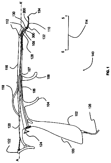
FIGS. 1A and 1B are, respectively, a side view and detail view of apparatus of the present invention for forming a gastrointestinal fold in accordance with the principles of the present invention;
FIGS. 2A and 2B are side-sectional views of a tissue grabbing assembly suitable for use with the apparatus of FIG. 1;
FIGS. 3A-3E are side views illustrating a method of using the apparatus of FIG. 1 to form a gastrointestinal fold;
FIGS. 4A-4C are side-sectional views of an anchor assembly and delivery system suitable for use with apparatus of the present invention;
FIGS. 5A and 5B are side-sectional views of another anchor assembly suitable for use with apparatus of the present invention;
FIGS. 6A and 6B are side-sectional views of another alternative anchor assembly suitable for use with apparatus of the present invention;
FIGS. 7A-7C are, respectively, a schematic side-sectional view of a unidirectionally adjustable anchor assembly suitable for use with apparatus of the present invention, schematic side-sectional views of alternative techniques for fixing the distal anchor of the assembly, and a cross-sectional view of the proximal anchor taken along section line A-A of FIG. 7A;
FIGS. 8A and 8B are schematic cross-sectional views illustrating the unidirectional adjustment capability of the anchor assembly of FIG. 7j
FIGS. 9A-9C are schematic cross-sectional views of alternative embodiments of the proximal anchor of the anchor assembly of FIG. 7j
FIGS. 10A and 10B are schematic cross-sectional views of an alternative unidirectionally adjustable anchor assembly suitable for use with apparatus of the present invention;
FIGS. 11A-11C are, respectively, a schematic side-view of another alternative unidirectionally adjustable anchor assembly suitable for use with the present invention, and cross-sectional views of the same taken along section line B-B of FIG. 11Aj
FIG. 12 is a schematic cross-sectional view of an alternative unidirectionally adjustable anchor assembly comprising pivoting paddles;
FIG. 13 is a schematic cross-sectional view of an alternative unidirectionally adjustable anchor assembly comprising spring material;
FIGS. 14A-14B are schematic side-sectional views of alternative unidirectionally adjustable anchor assemblies comprising one-way valves;
FIGS. 15A-15C are side-sectional and detail views of alternative unidirectionally adjustable anchor assemblies comprising slipknots;
FIGS. 16A-16C are, respectively, a schematic side-sectional view of a bidirectionally adjustable anchor assembly comprising a locking mechanism, and cross-sectional views of the same taken along section line C-C of FIG. 16Aj
FIGS. 17A-17D are perspective views of alternative anchors suitable for use with the anchor assemblies of the present invention;
FIGS. 18A-18D are side views of alternative apparatus for forming a gastrointestinal fold;
FIG. 19 is a cross-sectional view of the apparatus of FIGS. 18A-18D;
FIGS. 20A-20D are side views of further alternative apparatus for forming a gastrointestinal tissue fold in accordance with the principles of the present invention;
FIGS. 21A-21G are schematic side-sectional views of an anchor delivery system adapted for use with the adjustable anchor assemblies of FIGS. 7-17, illustrating a method of delivering the unidirectionally adjustable anchor assembly of FIG. 7 across a tissue fold;
FIGS. 22A and 22B are, respectively, a schematic side-view, partially in section, and an end-view of an alternative anchor delivery system adapted for use with the adjustable anchor assemblies of FIGS. 7-17, wherein the proximal anchor is disposed within a separate delivery tube;
FIG. 23 is a schematic side-sectional view or an alternative anchor delivery system adapted for use with the adjustable anchor assemblies of FIGS. 7-17, wherein both the proximal and distal anchors are loaded within the needle; and
FIG. 24 is a schematic side-sectional view of an alternative embodiment of the anchor delivery system of FIG. 23 comprising motion limitation apparatus.
Detailed description of the drawings
In accordance with the principles of the present invention, methods and apparatus are provided for intraluminally forming and securing gastrointestinal ("GI") tissue folds, for example, to reduce the effective cross-sectional area of a GI lumen. These methods and apparatus may be used to treat obesity by approximating the walls of a gastrointestinal lumen to narrow the lumen, thus reducing the area for absorption in the stomach or intestines. More particularly, the present 10 invention involves endoscopic apparatus that engages a tissue wall of the gastrointestinal lumen, creates a tissue fold and disposes an anchor assembly through the tissue fold. Preferably, the anchor assembly is disposed through the muscularis and/or serosa layers of the gastrointestinal lumen. In operation, a distal tip of the probe engages the tissue and then moves the engaged tissue to a proximal position relative to the catheter tip, thereby providing a substantially uniform placation of predetermined size.
Formation of a tissue fold preferably is accomplished using two tissue contact points that are separated by a linear or curvilinear distance, wherein the separation distance between the tissue contact points affects the length and/or depth of the fold. In operation, a tissue grabbing assembly engages the tissue wall in its normal state (i.e., non-folded and substantially flat), thus providing a first tissue contact point. The first tissue contact point then is moved to a position proximal of a second tissue contact point to form the tissue fold. An anchor assembly then may be extended across the tissue fold at the second tissue contact point.
More preferably, the first tissue contact point is used to engage and then stretch or rotate the tissue wall over the second tissue contact point to form the tissue fold. The tissue fold is then articulated to a position so that a portion of the tissue fold overlies the second tissue contact point at an orientation that is substantially normal to the tissue fold. An anchor then is delivered across the tissue fold at or near the second tissue contact point.
Referring to FIG. 1, apparatus 10 of the present invention comprises torqueable catheter 11 having distal region 12 from which first and second interconnected flexible tubes 13 and 14 extend, and proximal region 15 having handle 16 and actuator 17. Catheter 11 is configured for insertion through a patient's mouth and esophagus into the gastrointestinal lumen. Tissue grabbing assembly 18 is disposed on the distal end of flexible tube 13, and is coupled to actuator 17 via control wire 19 that extends through flexible tube 13.
As better illustrated in FIG. 1B, flexible tubes 13 and 14 are connected via hinge assembly 20 that comprises link 21 attached to flexible tube 13 at pivot point 22 and attached to flexible tube 14 at pivot point 23. Hinge assembly 20 prevents tissue grabbing assembly 18 from moving more than a predetermined distance relative to distal end 24 of flexible tube 14.
Still referring to FIG. 1B, flexible tubes 13 and 14 preferably include bendable sections 25 and 26, respectively, that comprise a plurality of through-wall slots 27 to enhance flexibility of the tube. Preferably, flexible tubes 13 and 14 are made from stainless steel with an etched or laser-cut slot pattern. More preferably, the slot pattern is a sinusoidal repeating pattern of slots perpendicular to the longitudinal axis of tubes 13 and 14.
Referring to FIGS. 2A and 2B, tissue grabbing assembly 18 comprises pair of jaws 28a, 28b arranged to rotate about pivot point 29 between an open configuration (FIG. 2A) and a closed configuration (FIG. 2B). Control wire 19 is coupled via pivot point 30 to arms 31a and 31b. Arms 31a and 31b are in turn pivotally coupled to jaws 28a and 28b, respectively, at pivot points 32a and 32b. Each of jaws 28a and 28b preferably includes sharpened teeth 33 disposed near its distal ends to facilitate grasping of the tissue wall of the GI lumen.
Control wire 19 is coupled to actuator 17 of handle 16 so that translation of the wire within flexible tube 13 causes the jaws to open or close. In particular, urging control wire distally (as indicated by arrow A in (FIG. 2A) moves pivot point 30 distally, thereby forcing the jaws to open. Urging control wire 19 proximally (as indicated by arrow B in FIG. 2B) moves pivot point 30 proximally, thereby forcing the jaws to close together. In alternative embodiments, tissue grabbing assembly 18 may comprise a grappling hook or fork, or plurality of needles coupled to the distal end of flexible tube 13.
Flexible tube 14 is affixed to and immovable within catheter 11, while flexible tube 13 is coupled to catheter 11 only via hinge 20. Accordingly, when control wire 19 is extended in the distal direction, flexible tube 13 is carried in the distal direction. When control wire 19 is retracted in the proximal direction, flexible tube remains stationary until jaws 28a and 28b close together, after which further retraction of control wire 19 by moving actuator 17 causes flexible tube 13 to buckle in bendable region 25, as described hereinafter.
Referring now to FIGS. 1 and 3A-3E, operation of apparatus 10 is described to create a tissue fold in a tissue wall of a GI lumen. In FIG. 3A, distal region 12 of catheter 11 is positioned within a patient's GI lumen transesophageally, and jaws 28a and 28b of tissue grabbing assembly 18 are opened by moving actuator 17 to the distal-most position on handle 16. As depicted in FIG. 3B, actuator 17 may then be moved proximally until the jaws of tissue grabbing assembly 18 engage a portion of tissue wall W at contact point P1.
Referring to FIG. 3C, after the tissue wall has been engaged at contact point P1, flexible tube 13 is urged proximally within catheter 11 by further proximal retraction of control wire 19 to stretch tissue wall W and create tissue fold F. During this movement of flexible tube 13, link 21 of hinge assembly 20 causes tissue grabbing assembly 18 to move from a position distal to distal end 24 of flexible tube 14, to a position proximal of distal end 24 of flexible tube 14. Bendable sections 25 and 26 of flexible tubes 13 and 14, respectively, accommodate any lateral motion caused by operation of hinge assembly 20. Advantageously, formation of fold F facilitates the penetration of the tissue wall by a needle and subsequent delivery of an anchor assembly, as described hereinafter.
Referring to FIG. 3D, additional proximal movement of actuator 17 causes flexible tubes 13 and 14 to buckle at bendable sections 25 and 26. Hinge assembly 20 transmits force applied to flexible tube 13 via control wire 19 and actuator 17 to the distal tip 24. Preferably, flexible tube 14 is configured so that distal tip 24 contacts, and is substantially perpendicular, to tissue fold F at contact point P2. As illustrated in FIG. 3E, once tissue fold F is stretched across distal tip 24 of flexible tube 14, sharpened needle or obturator 34 may be extended from distal tip 24 of flexible tube 14 to pierce all four layers of the tissue wall W. Sharpened needle or obturator 34 is inserted via inlet 35 to flexible tube 14 on handle 16 (see FIG. 1A).
As discussed above, the GI lumen comprises an inner mucosal layer, connective tissue, the muscularis layer and the serosa layer. To obtain a durable purchase, e.g., in performing a stomach reduction procedure, the staples or anchors used to achieve reduction of the GI lumen must engage at least the muscularis tissue layer, and more preferably, the serosa layer as well. Advantageously, stretching of tissue fold F across distal tip 24 permits an anchor to be ejected through both the muscularis and serosa layers, thus enabling durable gastrointestinal tissue approximation.
As depicted in FIG. 3E, after tissue fold F is stretched across distal tip 24 of flexible tube 14 to form contact point P2 with tissue wall W, needle 34 may be extended from distal tip 24 and through tissue fold F. Because needle 34 penetrates the tissue wall twice, it exits within the gastrointestinal lumen, thus reducing the potential for injury to surrounding organs. Once the needle has penetrated tissue fold F, an anchor assembly is ejected through distal tip 24 as described hereinbelow.
With respect to FIGS. 4A-4C, a first embodiment of an anchor assembly suitable for use with the apparatus of the present invention is described. Anchor assembly 36 comprises T-anchor assembly having distal rod 38a and proximal rod 38b connected by suture 39. The precise shape, size and materials of the anchors may vary for individual applications. In addition, the suture material also may vary for individual applications. By way of example, the suture material may consist of monofilament wire, multifilament wire or any other conventional suture material. Alternatively, suture 39 may comprise elastic material, e.g. a rubber band, to facilitate adjustment of the distance between the proximal and distal rods. Suture 39 extends through a pair of through-holes 40 in each rod, thereby forming a loop. Alternatively, suture 39 may be attached to the rods via an eyelet or using a suitable adhesive. Preferably, through-holes 40 are located near the center of the rods 38a and 38b.
Referring to FIG. 4B, rods 38a and 38b may be delivered through needle 34 (see FIG. 3E) using push rod 42. Push rod 42 is adapted to freely translate through flexible tube 14 and needle 34. Push rod 42 is preferably flexible, so that it may slide through bendable section 26 of flexible tube 14. In addition, push rod 42 may include notch 43 near its distal end to facilitate grasping and tensioning suture 39 after anchor delivery.
During anchor delivery, the longitudinal axis of distal rod 38a is substantially parallel to the longitudinal axis of needle 34. However, once distal rod 38a is ejected from needle 34, suture tension induces the rod to rotate approximately 90 degrees about its longitudinal axis, so that its longitudinal axis is substantially perpendicular to the longitudinal axis of needle 35. This rotation of distal rod 38a prevents it from being pulled back through tissue wall W.
Referring to FIG. 4C, once rod 38a is ejected on the distal side of fold F, needle 35 is retracted and push rod 42 is used to eject rod 38b on the proximal side of tissue fold F. Like distal rod 38a, tension in the suture causes proximal rod 38b to rotate about 90 degrees once it is ejected from the needle. Notch 43 in push rod 42 then may be employed to tighten suture 39 by any of a variety of mechanisms. Alternatively, suture 39 may comprise an elastic material that dynamically tightens the rods against tissue fold F.
Referring now to FIG. 5A, according to other embodiments, the anchor assembly comprises a T-anchor assembly suitable to be disposed over obturator 50. More particularly, distal rod 38a includes through-hole 51 dimensioned for the passage of obturator tip 52, and obturator 50 is translatably inserted through flexible tube 14 via inlet 35 of handle 16 (see FIG. 1A). Proximal rod 38b may be a solid rod that does not include a through-hole for passage of obturator 50. Alternatively, proximal rod 38b may include a throughhole for the passage of the obturator. Preferably, obturator tip 52 is sharpened to facilitate tissue penetration.
With respect to FIG. 5B, once rod 38a is ejected on the distal side of fold F, it rotates into a position substantially parallel to tissue wall W and perpendicular to the longitudinal axis of the obturator. Obturator 50 then is retracted and proximal rod 38b is ejected from flexible tube 14. More particularly, when flexible tube 14 is retracted from tissue wall W, proximal rod 38b is pulled through distal tip 24. Proximal rod 38b then rotates substantially 90 degrees as it is ejected from flexible tube 14 so that rod 38b is urged against tissue wall W.
Referring to FIG. 6A, according to further embodiments, anchor assembly 55 comprises a T-anchor assembly similar to the embodiment depicted in FIG. 4A. However, anchor assembly 55 includes fine wire tether 56 that may be twisted to maintain the tension between rods 38a and 38b.
With respect to FIG. 6B, a method of delivering anchor assembly 55 is described. Initially, distal rod 38a is delivered across both tissue walls using needle 34. The needle then is retracted to release distal rod 38a so that it engages the tissue wall. Next, needle 34 is retracted to release proximal rod 38b, so that it too rotates into engagement with the tissue wall. A proximal portion of the wire tether is captured by notch 43 of push rod 42 (see FIG. 4B), and the push rod is rotated to cause proximal rod 38b to clamp down on the tissue fold. Because wire tether 56 is twisted by rotation of push rod 42, it maintains the desired force on the tissue walls.
Referring now to FIG. 7, a unidirectionally adjustable anchor assembly suitable for use with apparatus of the present invention is described. Anchor assembly 60 comprises distal anchor 62 and unidirectionally adjustable proximal anchor 64, which are connected by suture 39. Distal anchor 62 is translationally fixed with respect to suture 39. Such fixation may be achieved in a variety of ways. For example, as seen in FIG. 7A, distal anchor 62 may comprise a pair of through-holes 63, located near the center of anchor 62 and through which suture 39 is threaded and tied off at knot 65.
FIG. 7B provides alternative techniques for fixing the distal anchor. As seen in FIG. 7B(i), distal anchor 62 may comprise hollow tube T having opening 0. A distal end of suture 39 is passed through opening 0 and formed into knot K, which is dimensioned such that it cannot pass through opening 0, thereby fixing the distal anchor with respect to the suture. In order to facilitate formation of knot K, distal anchor 62 optionally may comprise distal opening DO, which is dimensioned such that knot K may pass therethrough. The distal end of suture 39 may be passed through distal 17 opening DO, knotted, and then pulled back within hollow tube T of anchor 62 until it catches at opening o.
A drawback of the fixation technique described with respect to FIG. 7B(i) is a risk of suture 39 being torn or cut due to rubbing against opening o. In FIG. 7B (ii), hollow tube T comprises first end E to which is connected wire loop L, which may be formed, for example from a nickel-titanium alloy ("Nitinol"). Suture 39 passes through the wire loop before terminating at knot K. Knot K is dimensioned such that it cannot pass back through the wire loop. Wire loop L directs suture 39 through opening 0, thereby reducing rubbing of the suture against the opening and reducing a risk of tearing or cutting of suture 39.
FIG. 7B (iii) provides yet another alternative technique for fixing the distal anchor with respect to the suture. Distal anchor 62 again comprises hollow tube T having opening o. Rod R is disposed within tube T, and the ends of the tube may be either closed or crimped to rod R, such that the rod is maintained within the tube. The distal end of suture 39 is threaded through opening 0, around rod R, and back out opening o. The suture is then knotted at knot K, thereby fixing distal anchor 62 with respect to suture 39.
In addition to the techniques shown in FIGS. 7A and 7B, suture 39 alternatively may be fixed with respect to anchor 62 by other means, for example, via a knotted eyelet or via a suitable adhesive. Additional techniques will be apparent to those of skill in the art. While anchor 62 is illustratively shown as a rod- or T-type anchor, any of a variety of anchors, per se known, may be used as distal anchor 62. Exemplary anchors are described in co-pending U.S. patent application Ser. No. 10/612,170, filed Jul. 1, 2003, which is incorporated herein by reference in its entirety. Additional anchors are described hereinbelow with respect to FIG. 17.
Referring again to FIG. 7A, adjustable proximal anchor 64 comprises outer cylinder 66 having first end 67a and second end 67b, as well as first opening 68a and second opening 68b. First and second openings 68 are preferably disposed near the center of cylinder 66 and approximately 180.degree. apart. Anchor 64 further comprises first flexible rod 70a and second flexible rod 70b, both of which are disposed within outer cylinder 66 and coupled to first and second ends 67 of cylinder 66. Rods 70 may be formed, for example, from Nitinol or from a polymer, and may be separated from one another by small gap G. As with the previous anchor assemblies, the precise shape, size and materials of the anchors and suture may vary as required for specific applications.
As best seen in FIG. 7C, suture 39 passes from distal anchor 62 through first opening 68a of proximal anchor 64, around second flexible rod 70b, around first flexible rod 70a, between rods 70a and 70b, and out through second opening 68b. This suture winding provides a unidirectional adjustment capability that allows a length L of suture 39 disposed between distal anchor 62 and proximal anchor 64 to be shortened. However, the suture winding precludes an increase in length L. FIG. 8 illustrate the mechanism of this unidirectional adjustment capability in greater detail. Optionally, suture 39 may be tied off proximal of anchor 64 at knot 69, thereby forming a proximal loop of suture to facilitate deployment and/or adjustment of anchor assembly 60.
In FIG. 8A, a proximally-directed force F.sub.1 is applied to suture 39 proximal of adjustable anchor 64, while anchor 64 is held stationary or is advanced 19 distally. A portion of force F.sub.1 is transferred through suture 39 to second flexible rod 70b, which causes rod 70b to bow, thereby increasing gap G and allowing suture 39 to freely pass between rods 70a and 70b and through proximal anchor 64, facilitating unidirectional adjustment. When anchor 64 is held stationary while suture 39 is retracted proximally, distal anchor 62 retracts proximally towards anchor 64. Alternatively, when anchor 64 is advanced distally while suture 39 is retracted proximally, distal anchor 62 either remains stationary or retracts proximally towards proximal anchor 64, depending upon a degree of distal advancement of proximal anchor 64. Regardless, length L of suture 39 disposed between anchors 62 and 64 is decreased, thereby unidirectionally adjusting a distance between the anchors.
In FIG. 8B, a distally-directed force F.sub.2 is applied to suture 39 distal of adjustable anchor 64. Force F.sub.2 may be applied, for example, by tissue compressed between anchors 62 and 64. Compressed tissue stores energy in a manner similar to a compression spring and seeks to push anchors 62 and 64 apart after unidirectional tightening. Force F.sub.2 causes the loop of suture 39 around first and second rods 70 to tighten, thereby bowing both rods inward and closing gap G such that suture 39 is friction locked between first and second flexible rods 70. In this manner, the length L of suture between anchors 62 and 64 may be selectively decreased but cannot be increased.
As will be apparent to those of skill in the art, the magnitude of force required to unidirectionally adjust length L may be altered in a variety of ways. For example, a length, flexibility or diameter of rods 70 may be altered. Likewise, the elasticity or diameter of suture 39 may be altered. Initial gap G may be increased or decreased. Further still, the materials used to form rods 70 and suture 39 may be changed to alter material 70 or suture 39 may comprised a lubricous coating. Additional methods for varying the magnitude of force, a few of which are described hereinbelow with respect to FIG. 9, will be apparent in view of this disclosure and are included in the present invention.
Referring now to FIG. 9, alternative anchors 64 are described. In FIG. 9A, flexible rods 70 of proximal adjustable anchor 64' are rotated with respect to openings 68 (or vice versa). When utilizing the suture winding described in FIGS. 7 and 8, rotation of rods 70 up to 108.degree. clockwise progressively increased magnitude of the friction lock is increased when force is applied in the manner described with respect to FIG. 8B. However, friction is also increased when unidirectionally adjusting the length of suture between the proximal and distal anchors by applying force in the manner described with respect to FIG. 8A. Rotation of rods 70 more than about 108.degree. clockwise would case anchor 64' to friction lock regardless of which direction force were applied suture 39, thereby negating the unidirectional adjustment capability. Counterclockwise rotation of rods 70 with respect to openings 68 would initially reduce friction during force application to suture 39 in either direction. It is expected that counterclockwise rotation in excess of about 90.degree. would eliminate the friction lock described in FIG. 8B and allow bidirectional adjustment. Continued counterclockwise rotation beyond about 450.degree. would reverse the directions of friction lock and unidirectional adjustment, while counterclockwise rotation beyond about 720.degree. would result in friction lock regardless of which direction force were applied to suture 39.
As discussed previously, openings 68 of cylinder 66 of anchor 64 are preferably disposed approximately 180.degree. apart from one another. However, in order to increase the friction lock force without significantly increasing friction during unidirectional adjustment, first opening 68a may be rotated counterclockwise with respect to second opening 68b (or vice versa), as seen with anchor 64'' of FIG. 9B. In this manner, first opening 68a is no longer in line with rods 70, while second opening 68b remains in line with rods 70. When force F.sub.1 is applied to anchor 64'', second flexible rod 70b is able to bow outward and increase gap G, thereby facilitating unidirectional adjustment. Likewise, when force F.sub.2 is applied to the anchor, gap G is closed more tightly upon suture 39, thereby increasing the friction lock force. If first opening 68a alternatively were rotated clockwise with respect to the second opening, it is expected that the friction lock force would be decreased.
In FIG. 9C, proximal adjustable anchor 64''' comprises an alternative suture winding. Suture 39 passes from distal anchor 62 through first opening 68a of anchor 64''', around second flexible rod 7Gb, around first flexible rod 70a, back around second flexible rod 70b, between rods 70a and 70b, and out through second opening 68b. As with the suture winding described with respect to anchor 64 of FIGS. 7 and 8, the suture winding illustrated in FIG. 9C provides a unidirectional adjustment capability that allows a length L of suture 39 disposed between distal anchor 62 and proximal anchor 64''' to be shortened. However, this suture winding 22 precludes an increase in length L. Additional unidirectionally adjustable suture windings will be apparent to those of skill in the art.
With reference to FIG. 10, an alternative unidirectionally adjustable anchor comprising three rods is described. Anchor assembly 80 comprises distal anchor 62 and proximal anchor 82. Unidirectionally adjustable proximal anchor 82 comprises outer cylinder 84 having first end 85a and second end 85b (not shown), as well as first opening 86a and second opening 86b. First and second openings 86 are preferably disposed near the center of cylinder 84 and approximately 180.degree. apart. Anchor 82 further comprises first flexible rod 88a, second flexible rod 88b and third flexible rod 88c, all of which are disposed within outer cylinder 66 and coupled to first and second ends 85 of cylinder 64. Rods 88 are separated from one another by gaps G.sub.1 and G.sub.2.
Suture 39 passes from distal anchor 62 through first opening 86a of proximal anchor 82, around first rod 88a, between first rod 88a and second rod 88b, between second rod 88b and third rod 88c, around third rod 88c, back to and around first rod 88a, and out through second opening 86b. As seen in FIG. 10A, when force F1 is applied to suture 39, gaps G.sub.1 and G.sub.2 remain open, thereby facilitating unidirectional adjustment/shortening of length L of suture 39 disposed between distal anchor 62 and proximal anchor 82. As seen in FIG. 10B, when force F.sub.2 is applied to suture 39, gaps G.sub.1 and G.sub.2 close down upon suture 39, thereby forming a friction lock that precludes an increase in length L of suture 39.
Referring now to FIG. 11, an alternative three rod anchor assembly is described. The unidirectionally adjustable anchors described hereinabove with respect to FIGS. 7-10 all comprise rods disposed within a cylinder 23 having openings for passage of a suture. The openings act to center the suture with respect to the rods and can be used to alter magnitudes of force applied during adjustment and friction locking, as discussed previously. However, such openings present a risk of tearing or cutting the suture as the suture slides through the openings.
As seen in FIG. 11, anchor assembly 90 comprises distal anchor 62 and proximal anchor 92. Unidirectionally adjustable proximal anchor 92 comprises first flexible rod 94a and second flexible rod 94b, as well as rigid rod 96, which is preferably larger in diameter than first and second rods 94. Flexible rods 94 are preferably fabricated from Nitinol or a polymer, while rigid rod 96 is preferably fabricated from stainless steel or a polymer. Alternative materials will be apparent to those of skill in the art.
Anchor 92 further comprises first outer cylinder 98a and second outer cylinder 98b, which are crimped to the ends of first and second rods 94, and rigid rod 96. As an alternative to crimping, first and second cylinders 98 may each comprise an end cap (not shown) to which the rods are coupled. First and second cylinders 94 do not span a central portion of anchor 92. Flexible rods 94 are separated from one another by gap G.sub.1, while rods 94 are separated from rigid rod 96 by gap G.sub.2.
Anchor 92 comprises three rods, but, unlike anchor 82 of FIG. 10, suture 39 is only wrapped around two of them to achieve unidirectional adjustment. As best seen in FIGS. 118 and 11C, the illustrative suture winding of anchor assembly 90 is similar to that described previously with respect to anchor assembly 60 of FIGS. 7 and 8. The break between first and second cylinders 98 acts to center suture 39 with respect to the 24 rods, as seen in FIG. 11A, while rigid rod 96 acts to stiffen and reduce rotation of anchor 92 as it directs suture 39 about flexible rods 94.
Suture 39 passes from distal anchor 62 to proximal anchor 92, between rigid rod 96 and flexible rods 94, around second flexible rod 94b, around first flexible rod 94a, between rigid rod 96 and first flexible rod 94a, between flexible rods 94a and 94b, and out. As seen in FIG. 11A, when force F1 is applied to suture 39, flexible rods 94 are forced apart and gap G.sub.1 widens while gap G2 remains substantially constant, thereby allowing unidirectional adjustment of length L of suture 39 disposed between distal anchor 62 and proximal anchor 92. As seen in FIG. 11B, when force F.sub.2 is applied to suture 39, gap G.sub.1 closes down upon suture 39, thereby forming a friction lock that precludes an increase in length L of suture 39. Gap G.sub.2 again remains substantially constant.
The description continues in the full USPTO document.
 Lapsed, fee not paid11 drawings