Cross reference to related application
The present application claims priority from Japanese Patent Application No. 2011-001054, which was filed on Jan. 6, 2011, the disclosure of which is herein incorporated by reference in its entirety.
Background of the invention
1. Field of the invention
The present invention relates to a liquid ejection apparatus configured to eject liquid such as ink, a controller used therefor, and a nonvolatile storage medium storing a program to be executed by the liquid ejection apparatus.
2. Description of the related art
There is known a liquid ejection apparatus configured to supply cleaning liquid onto a face of a conveyance member and remove or wipe foreign matters (such as recording liquid (e.g., ink) and paper dust) together with the cleaning liquid by a wiper. In this liquid ejection apparatus in the form of an ink-jet recording apparatus, the cleaning liquid is supplied onto a face of a conveyance belt (conveyance member), and foreign matters are removed together with the cleaning liquid by a blade (wiper).
Summary of the invention
However, in this liquid ejection apparatus, when the recording liquid and the cleaning liquid are mixed with each other on the face of the conveyance member, cleaning ability of the cleaning liquid decreases, making it difficult to perform good wiping.
This invention has been developed in view of the above-described situations, and it is an object of the present invention to provide a liquid ejection apparatus capable of performing good wiping while preventing cleaning ability of cleaning liquid from decreasing, a controller used in the liquid apparatus, and a nonvolatile storage medium storing a program to be executed by the liquid ejection apparatus.
The object indicated above may be achieved according to the present invention which provides a liquid ejection apparatus comprising: a liquid ejection head having an ejection face in which a plurality of ejection openings are formed, the liquid ejection head being configured to eject recording liquid through the plurality of ejection openings; a conveyance member having a face that is disposed so as to be opposed to the ejection face and that is moved while supporting a recording medium thereon to convey the recording medium; a cleaning-liquid supply portion configured to supply cleaning liquid onto the face; a wiper movable relative to the face while contacting the face to remove the recording liquid existing on the face; and a cleaning-operation executing section configured to execute a first cleaning operation including (i) a first operation for reducing an amount of the recording liquid on the face and (ii) a second operation in which the cleaning liquid is supplied onto the face by the cleaning-liquid supply portion after the that operation, and then the recording liquid and the cleaning liquid on the face are removed by the wiper.
The object indicated above may be achieved according to the present invention which provides a controller for a liquid ejection apparatus, the liquid ejection apparatus comprising: a liquid ejection head having an ejection face in which a plurality of ejection openings are formed, the liquid ejection head being configured to eject recording liquid through the plurality of ejection openings; a conveyance member having a face that is disposed so as to be opposed to the ejection face and that is moved while supporting a recording medium thereon to convey the recording medium; a cleaning-liquid supply portion configured to supply cleaning liquid onto the face; and a wiper movable relative to the face while contacting the face to remove the recording liquid existing on the face, the controller comprising: a cleaning-operation executing section configured to execute a first cleaning operation including (i) a first operation for reducing an amount of the recording liquid on the face and (ii) a second operation in which the cleaning liquid is supplied onto the face by the cleaning-liquid supply portion after the first operation, and then the recording liquid and the cleaning liquid on the face are removed by the wiper.
The object indicated above may be achieved according to the present invention which provides a nonvolatile storage medium storing a program to be executed by a liquid ejection apparatus, the liquid ejection apparatus comprising: a liquid ejection head having an ejection face in which a plurality of ejection openings are formed, the liquid ejection head being configured to eject recording liquid through the plurality of ejection openings; a conveyance member having a face that is disposed so as to be opposed to the ejection face and that is moved while supporting a recording medium thereon to convey the recording medium; a cleaning-liquid supply portion configured to supply cleaning liquid onto the face; and a wiper movable relative to the face while contacting the face to remove the recording liquid existing on the face, the program being designed to execute a first cleaning operation including (i) a first operation for reducing an amount of the recording liquid on the face and (ii) a second operation in which the cleaning liquid is supplied onto the face by the cleaning-liquid supply portion after the first operation, and then the recording liquid and the cleaning liquid on the face are removed by the wiper.
Brief description of the drawings
The objects, features, advantages, and technical and industrial significance of the present invention will be better understood by reading the following detailed description of embodiments of the invention, when considered in connection with the accompanying drawings, in which:
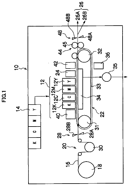
FIG. 1 is a side view generally showing an internal structure of an ink-jet printer as a first embodiment of a liquid ejection apparatus to which the present invention is applied;
FIG. 2 is a plan view showing a channel unit and actuator units of an ink-jet head of the printer in FIG. 1;
FIG. 3 is an enlarged view showing an area III enclosed by a one-dot chain line in FIG. 2;
FIG. 4 is a partial cross-sectional view taken along line IV-IV in FIG. 3;
FIG. 5A is a side view partly showing a state of a wiper in a first step, and FIG. 5B is a side view partly showing a state of the wiper in a second step;
FIG. 6 is a perspective view showing a wiping unit;
FIGS. 7A-7G are views for explaining operations of a sub-wiper in its wiping;
FIG. 8 is a block diagram showing an electric configuration of the printer in FIG. 1;
FIG. 9 is a flow-chart showing a control of a wiping executed by a controller of the printer in FIG. 1; and
FIGS. 10A-10E are side views generally showing processings in a first sequence, wherein FIG. 10A shows a middle of the first step, FIG. 10B shows a completion of the first step, FIG. 10C shows a middle of a wiper cleaning, FIG. 10D shows a liquid supply in the second step, and FIG. 10E shows a start of wiping in the second step.
Detailed description of the embodiments
Hereinafter, there will be described embodiments of the present invention by reference to the drawings.
First, there will be explained an overall construction of an ink-jet printer 1 as a first embodiment of a liquid ejection apparatus of the present invention with reference to FIG. 1.
The printer 1 includes a casing 1a having a rectangular parallelepiped shape. A sheet-discharge portion 31 is provided at an upper portion of a top plate of the casing 1a. An inner space of the casing 1a is divided into spaces A, B, and C in order from an upper side thereof. A sheet-supply unit 1b is disposed in the space B. In the spaces A, B is formed a sheet conveyance path extending from the sheet-supply unit 1b to the sheet-discharge portion 31.
In the space A, there are disposed a sheet sensor 32, the four heads 10, a cleaning-liquid supply device 70 (as one example of a cleaning-liquid supply portion), a conveyance unit 21, a guide unit, a wiping unit 40, a controller 1p, and so on.
The sheet-convey unit 21 includes: (a) belt rollers 6, 7; (b) an endless conveyance belt 8 (as one example of a conveyance member) wound around the rollers 6, 7; (c) a nip roller 4 and a peeling plate 5 disposed outside the conveyance belt 8; (d) platens 9a, 9b disposed inside the conveyance belt 8; and so on. The belt roller 7 is a drive roller which is rotated in a clockwise direction in FIG. 1 by a drive power of a conveyance motor 121 (see FIG. 8). The rotation of the belt roller 7 rotates or circulates the conveyance belt 8 in its circumferential direction in FIG. 1. The belt roller 6 is a driven roller which is rotated in the clockwise direction in FIG. 1 in accordance with the rotation of the conveyance belt 8. The nip roller 4 is disposed so as to face the belt roller 6 and used for pressing a sheet P (as one example of a recording medium) supplied from an upstream-side guide portion (which will be explained below), onto a face 8a of the conveyance belt 8. The peeling plate 5 is disposed so as to face the belt roller 7 and used for peeling off the sheet P from the face 8a to guide the sheet P toward a downstream-side guide portion (which will be explained below). The platen 9a is disposed so as to face the four heads 10 and to support an upper portion (an upper loop) of the conveyance belt 8 from an inside thereof. As a result, a predetermined space appropriate for recording is formed between the face 8a and lower faces (ejection faces 10a) of the respective heads 10.
Each head 10 (as one example of a liquid ejection head) is a line head having a generally rectangular parallelepiped shape elongated in a main scanning direction. In recording (forming an image), the four heads 10 respectively eject inks (each as one example of a recording liquid) of four colors, namely, magenta, cyan, yellow, and black, from the lower faces (the ejection faces 10a) thereof. The four heads 10 are arranged in a sub-scanning direction (perpendicular to the main scanning direction) at predetermined pitches and supported by the casing 1a via a frame 3.
The guide unit includes the upstream-side guide portion and the downstream-side guide portion disposed on opposite sides of the conveyance unit 21. The upstream-side guide portion includes two guides 27a, 27b and a pair of conveyance rollers 26. The upstream-side guide portion connects the sheet-supply unit 1b and the conveyance unit 21 to each other. The downstream-side guide portion includes two guides 29a, 29b and two pairs of conveyance rollers 28. The downstream-side guide portion connects the conveyance unit 21 and the sheet-discharge portion 31 to each other.
The cleaning-liquid supply device 70 includes a tank storing cleaning liquid therein and a multiplicity of nozzles communicating with the tank and opening in a lower face of the device 70. The cleaning-liquid supply device 70 ejects the cleaning liquid from the nozzles onto the face 8a. The cleaning liquid may be any liquid as long as the liquid is suitable for cleaning the face 8a. For example, water, clear ink (e.g., colorless transparent liquid not containing dyes or pigments, or the like) is used as the cleaning liquid.
The wiping unit 40 includes a sub-wiper 41, a wiper 42, a sub-wiper cleaner 44 (see FIG. 6), and a wiper cleaner 45. The wiper 42 and the wiper cleaner 45 are disposed so as to be opposed to the face 8a of a lower loop (portion) of the conveyance belt 8. In the wiping, the sub-wiper 41, while contacting the face 8a of the lower loop, is moved in the main scanning direction from its home position located on one side of the lower loop of the conveyance belt 8. The sub-wiper cleaner 44 (see FIG. 6) is disposed on the other side of the lower loop of the conveyance belt 8 (the sub-wiper cleaner 44 is disposed on the other side of the lower loop from the home position of the sub-wiper 41). The platen 9b is disposed inside the conveyance belt 8 at a position located on the other side of the conveyance belt 8 from a portion thereof contacted by the wipers 41, 42 in the wiping. Since the platen 9b supports the lower loop of the conveyance belt 8 from the inside thereof, it is possible to prevent the conveyance belt 8 from being deformed by pressing forces of the wipers 41, 42 in the wiping of the wipers 41, 42, resulting in good wiping.
The sheet-supply unit 1b includes a sheet-supply tray 23 and a sheet-supply roller 25. The sheet-supply tray 23 is mountable on and removable from the casing 1a. The sheet-supply tray 23 has a box shape opening upward and can accommodate various sizes of sheets P. The sheet-supply roller 25 supplies, to the upstream-side guide portion, an uppermost one of the sheets P in the sheet-supply tray 23.
The controller 1p controls operations of the components of the printer 1 to control entire operations of the printer 1.
In order to record an image on the sheet P on the basis of image data supplied from an external device such as a PC connected to the printer 1, the controller 1p controls: a preliminary operation for the recording; the supplying, conveying, and discharging of the sheet P; an ink ejecting operation synchronized with the conveyance of the sheet P; and other operations for the recording. Specifically, on the basis of a recording command received from the external device, the controller 1p controls driving devices for driving: a sheet supply motor 125 (see FIG. 8) for the sheet-supply roller 25; a conveyance motor 127 (see FIG. 8) for the conveyance rollers of the guide portions; the conveyance motor 121 (see FIG. 8), the heads 10; and so on. The sheet P supplied from the sheet-supply tray 23 is conveyed to the conveyance unit 21 by the conveyance rollers 26. When the sheet P passes through a position just under the heads 10 in the sub-scanning direction, the heads 10 respectively eject inks of respective colors to form a color image on the sheet P. The ink ejecting operation for the recording is performed on the basis of a detection signal transmitted from the sheet sensor 32 for sensing a leading end of the sheet P. The sheet P is then peeled off from the peeling plate 5 and conveyed upward by the two conveyance rollers 28. Further, the sheet P is discharged onto the sheet-discharge portion 31 through an opening 30 formed in an upper portion of the printer 1.
Here, the sub-scanning direction is a direction parallel to a direction (a part of a conveyance direction) in which the sheet P conveyed by the conveyance unit 21 is conveyed through the position just under the heads 10, and the main scanning direction is a direction parallel to the horizontal plane and perpendicular to the sub-scanning direction.
As will be described below, the controller 1p executes controls for wiping and removing foreign matters (such as the ink and paper dust) from the face 8a of the conveyance belt 8.
In the space C, a cartridge unit 1c is disposed so as to be mountable on and removable from the easing 1a. The cartridge unit 1c includes a tray 35 and four cartridges 39 accommodated in the tray 35 side by side. The cartridges 39 respectively store the inks of four colors and respectively communicate with the heads 10 via tubes, not shown. The inks stored in the respective cartridges 39 are supplied to the respective heads 10 at appropriate timings.
There will be next explained the construction of each head 10 with reference to FIGS. 2-4 in detail. It is noted that, in FIG. 3, pressure chambers 16 and apertures 15 are illustrated by solid lines for easier understanding purposes though these elements are located under the actuator units 17 and thus should be illustrated by broken lines. It is further noted that, since the four heads 10 have the same construction, the following explanation will be given for one of the heads 10 for the sake of simplicity.
The head 10 is a stacked body including: a reservoir unit, not shown; a channel unit 12; eight actuator units 17 fixed to an upper face 12x of the channel unit 12 (see FIG. 2); Flexible Printed Circuits (FPCs, see FIG. 4) 19 bonded to the respective actuator units 17; and so on which are stacked in an upward and downward direction. The reservoir unit has a channel including a reservoir for temporarily storing the ink supplied from the cartridge 39 (see FIG. 1). The channel unit 12 has channels each extending from a corresponding one of openings 12y (see FIG. 2) formed in the upper face 12x to a corresponding one of ejection openings 14a formed in the lower face (the ejection face 10a). Each of the actuator units 17 has piezoelectric actuators respectively for the ejection openings 14a.
Projections and recesses are formed on and in a lower face of the reservoir unit. The projections are bonded to areas of the upper face 12x of the channel unit 12 on which the actuator units 17 are not disposed (i.e., areas including the openings 12y and enclosed by two-dot chain lines in FIG. 2). A distal end face of each of the projections has an opening connected to the reservoir and opposed to a corresponding one of the openings 12y of the channel unit 12. As a result, individual channels 14 and the reservoir are communicated with each other via the above-described openings. The recesses are opposed to the upper face 12x of the channel unit 12, surfaces of the actuator units 17, and surfaces of the FPCs 19 with slight clearances therebetween.
The channel unit 12 is a stacked body constituted by nine metal rectangular plates 12a-12i (see FIG. 4) having generally the same size and bonded to one another. As shown in FIGS. 2, 3, and 4, the channels of the channel unit 12 include (a) manifold channels 13 respectively having the openings 12y at respective one ends, (b) sub-manifold channels 13a each branched from a corresponding one of the manifold channels 13, and (c) the individual channels 14 each extending from an outlet of a corresponding one of the sub-manifold channels 13a to a corresponding one of the ejection openings 14a via a corresponding one of the pressure chambers 16. As shown in FIG. 4, each of the individual channels 14 is formed for a corresponding one of the ejection openings 14a so as to have the aperture 15 functioning as a restrictor for adjusting a channel resistance. In areas of the upper face 12x to which the respective actuator units 17 are bonded, generally rhombic openings respectively for exposing the pressure chambers 16 are formed so as to be arranged in matrix. In areas of the lower face (the ejection face 10a) which are respectively opposed to the areas to which the respective actuator units 17 are bonded, the ejection openings 14a are formed in matrix in the same pattern as that of the pressure chambers 16.
As shown in FIG. 2, the actuator units 17 each having a trapezoid shape in plan view are arranged on the upper face 12x in two arrays in a staggered configuration. As shown in FIG. 3, each of the actuator units 17 covers the openings of the pressure chambers 16 formed in the area to which the actuator unit 17 is bonded. Though not shown in any figures, the actuator unit 17 includes: a plurality of piezoelectric layers expanding over a multiplicity of the pressure chambers 16; and electrodes interposing the piezoelectric layer in a thickness direction of the actuator unit 17. The electrodes include: individual electrodes provided for the respective pressure chambers 16; and a common electrode common for the pressure chambers 16. The individual electrodes are formed on a surface of an uppermost one of the piezoelectric layers.
Each of the FPCs 19 has wirings respectively corresponding to electrodes of the actuator unit 17, and driver ICs, not shown, are mounted on the wirings. One end of the FPC 19 is fixed to the actuator unit 17, and the other end thereof is fixed to a control board, not shown, of the head 10 (which is disposed on an upper side of the reservoir unit). Under the control of the controller 1p (see FIG. 1), the FPC 19 sends the driver ICs various drive signals outputted from the control board and sends the actuator units 17 signals produced by the driver ICs.
There will be next explained a construction of the wiping unit 40.
As shown in FIGS. 5A and 5B, the wiper 42 is constituted by a main body 42a and a wall 42b. The main body 42a and the wall 42b are formed of the same material (e.g., an elastic material such as a rubber) integrally with each other.
The main body 42a is a plate member mainly constitutes the wiper 42 and having a distal end (one end) contactable with the face 8a (i.e., a contactable portion of the wiper 42 which is contactable with the face 8a). A basal end (the other end) of the main body 42a is fixed to a shaft 42x extending in the main scanning direction. The main body 42a extends in the main scanning direction so as to be longer than the conveyance belt 8 in the main scanning direction (that is, a length of the main body 42a in the main scanning direction is longer than a width of the conveyance belt 8). Near the distal end of the main body 42a, the wall 42b is provided on a downstream face (right face in FIGS. 5A and 5B) of the main body 42a in a relative movement direction that is a direction in which the wiper 42 is moved relative to the face 8a in the wiping (hereinafter may be simply referred to as "relative movement direction"). As in the present embodiment, where the wiper 42 is stopped or at rest, and the conveyance belt 8 is moved, the relative movement direction is a direction opposite to a belt running direction of the conveyance belt 8 in which the conveyance belt 8 runs or is circulated. Where the conveyance belt 8 is stopped or at rest, and the wiper 42 is moved, the relative movement direction coincides with a direction of the movement of the wiper 42. Where the conveyance belt 8 is moved, and the wiper 42 is moved in a direction opposite to the belt running direction of the conveyance belt 8, the relative movement direction coincides with the direction of the movement of the wiper 42. The wall 42b projects from the downstream face of the main body 42a in a direction toward a downstream side thereof in the relative movement direction, and in a direction inclined toward the basal end of the main body 42a with respect to a direction perpendicular to the downstream face of the main body 42a. A length of the wall 42b in its projecting direction is shorter than a length of the main body 42a in a direction perpendicular to the shaft 42x. The wall 42b is provided so as to expand over an entire length of the main body 42a in the main scanning direction.
At times other than the wiping, the wiper 42 is located at a position distant from the conveyance belt 8, and in the wiping, the wiper 42 is located at a position at which the distal end of the main body 42a is held in deforming contact with the face 8a. In the wiping, the main body 42a is held in contact with an entire width of the face 8a so as to be inclined with respect to the face 8a as seen in the main scanning direction such that a lower portion of the main body 42a is located nearer to the downstream side thereof (i.e., a right side in FIG. 5) in the relative movement direction than an upper portion of the main body 42a. In other words, in the wiping, the main body 42a extends from the distal end thereof in a direction including a downward component in a vertical direction and a downstream component in the relative movement direction (i.e., a rightward and downward direction in FIG. 5). When the conveyance belt 8 is circulated in this state, the foreign matters on the face 8a are removed.
As shown in FIG. 6, a worm wheel 42h is provided on one end of the shaft 42x. The worm wheel 42h is connected to a motor 42M via gears 42g1, 42g2, 42g3. The gears 42g3, 42g2, 42g1 are rotated by the motor 42M, which rotates the worm wheel 42h with the shaft 42x. In this rotation, the main body 42a is rotated about the shaft 42x, thereby changing an angle of the main body 42a with respect to the face 8a as shown in FIGS. 5A and 5B (i.e., inclination angles .theta.1, .theta.2 of the main body 42a with respect to the face 8a toward the downstream side thereof in the relative movement direction as seen in the main scanning direction). It is noted that the gears 42g1, 42g2, 42g3, the motor 42M, the worm wheel 42h, and the shaft 42x are examples of an angle adjusting mechanism.
As shown in FIG. 6, the sub-wiper 41 is a plate member formed of an elastic material such as a rubber and extending in the sub-scanning direction.
A basal end of the sub-wiper 41 (i.e., an end portion thereof opposite to a distal end thereof) is fixed to a supporter 41a. The supporter 41a is supported by a shaft 41x extending in the sub-scanning direction so as to be rotatable about the shaft 41x. A pair of sliders 41s are respectively provided on opposite ends of the shaft 41x. The sliders 41s are slidably supported on respective bars 41b each extending in the main scanning direction. To each of the sliders 41s is fixed a lower portion of a corresponding one of belts 41c. One of the belts 41c is wound around pulleys 41p1, 41p2, and the other of the belts 41c is wound around pulleys 41p3, 41p4. The pulleys 41p1, 41p3 are provided on opposite ends of a roller 41r. In addition to the pulley 41p1, a gear 41g1 rotatable integrally with the pulley 41p1 is provided on one of the opposite ends of the roller 41r. The gear 41g1 is connected to a motor 41M via a gear 41g2. When the pulley 41p1 is rotated by the motor 41M, the belts 41c are circulated. The sliders 41s are in turn slid along the bars 41b, whereby the supporter 41a is moved in the main scanning direction while supporting the sub-wiper 41. A plate 41d extending in the main scanning direction is disposed on a lower side of the supporter 41a. During the movement of the sub-wiper 41 in the main scanning direction, a lower end 41a1 of the supporter 41a is held in sliding contact with a face of the plate 41d. The face of the plate 41d is flat except opposite ends thereof in the main scanning direction. The plate 41d has: a step face 41d1 on one of the opposite ends thereof in the main scanning direction (i.e., an upstream end portion in a direction indicated by arrow in FIG. 6 in which the sub-wiper 41 is moved in its wiping); and an inclined face 41d2 on the other of the opposite ends thereof in the main scanning direction. The step face 41d1 is lower than the face of the plate 41d except the opposite ends thereof in the main scanning direction. A protruding portion 41dp is provided on the face of the plate 41d at a boundary between the step face 41d1 and the other area on the face of the plate 41d (except the step face 41d1). It is noted that the supporter 41a is urged in a clockwise direction in FIG. 7A by an urging member such as a spring.
When the wiping is not performed, the sub-wiper 41 is positioned at the home position (see FIG. 7A). In this home position, the sub-wiper 41 is opposed to the face 8a in the vertical direction and is at rest at an angle .phi.1 (see FIG. 7B) with respect to the horizontal plane such that the distal end of the sub-wiper 41 does not contact the face 8a. When the sub-wiper 41 is to move from the home position in the main scanning direction by the motor 41M, as shown in FIGS. 7B, 7C, and 7D, the lower end 41a1 pivots or rotates while contacting an inclined face of the protruding portion 41dp near the step face 41d1. In this operation, the sub-wiper 41 pivots or rotates about the shaft 41x against an urging force of the urging member, whereby the angle of the sub-wiper 41 with respect to the horizontal plane is changed from .phi.1 to .phi.2 and then .phi.3 (.phi.1<.phi.2<.phi.3). As a result, the distal end of the sub-wiper 41 is brought into contact with the face 8a. Then, as shown in FIGS. 7D and 7E, the lower end 41a1 is moved over the protruding portion 41dp, and the sub-wiper 41 moves in the main scanning direction while keeping the angle .phi.3 to perform the wiping. During the wiping, the urging force of the urging member (i.e., a force in a direction directed so as to change the sub-wiper 41 from the angle .phi.2 to the angle .phi.1) is applied to the sub-wiper 41, but the sub-wiper 41 is kept at the angle .phi.3 because the lower end 41a1 is supported on the face of the plate 41d. When the sub-wiper 41 has reached the other end of the plate 41d in the main scanning direction, and the lower end 41a1 has reached the inclined face 41d2, as shown in FIG. 7F, the lower end 41a1 comes off or is released from the face of the plate 41d (the inclined face 41d2). In accordance with this operation, the sub-wiper 41 pivots or rotates about the shaft 41x by the urging force of the urging member, whereby the angle of the sub-wiper 41 is changed from .phi.3 to .phi.2 and then .phi.1. As a result, the distal end of the sub-wiper 41 comes off or is released from the face 8a, and the wiping of the sub-wiper 41 is completed. After the wiping, the sub-wiper 41 is moved in the main scanning direction (specifically in a direction in the wiping) at the angle .phi.1 to a position at which the distal end is brought into contact with the sub-wiper cleaner 44 (see FIG. 6). After the sub-wiper cleaner 44 has cleaned the distal end, the sub-wiper 41 is moved at the angle .phi.1 in a direction opposite to the direction in the wiping (see FIG. 7G) to return to the home position. It is noted that, in the wiping, the sub-wiper 41 is moved in the main scanning direction from one end to the other end of the conveyance belt 8 in its widthwise direction in the state in which the distal end is held in deforming contact with the face 8a. As a result, the foreign matters on the face 8a are removed.
The foreign matters removed by the wipers 41, 42 are received by respective receiving trays, not shown, located below the respective wipers 41, 42.
Each of the wiper cleaners 44, 45 (see FIG. 6) is a cylindrical member formed of a material capable of absorbing the ink such as a sponge. The wiper cleaners 44, 45 are used respectively for cleaning the distal ends of the respective wipers 41, 42. The sub-wiper cleaner 44 is elongated in the sub-scanning direction, and the wiper cleaner 45 is elongated in the main scanning direction. The sub-wiper cleaner 44 is longer than the sub-wiper 41 in the sub-scanning direction, and the wiper cleaner 45 is longer than the wiper 42 in the main scanning direction. The wiper cleaners 44, 45 are always located at their respective positions that are distant from the face 8a.
A shaft 44x extending in the sub-scanning direction is fitted in and fixed to a center of the sub-wiper cleaner 44. A pulley 44p1 is provided on one end of the shaft 44x. A motor 44M and a pulley 44p2 fixed to an output shaft of the motor 44M are disposed on a lower side of the pulley 44p1. A belt 44b is wound around the pulleys 44p1, 44p2. When the pulley 44p2 is rotated by the motor 44M, the belt 44b is circulated, which rotates the pulley 44p1 with the shaft 44x. As a result, the sub-wiper cleaner 44 is rotated about the shaft 44x.
A shaft 45x extending in the main scanning direction is fitted in and fixed to a center of the wiper cleaner 45. A pulley 45p1 is provided on one end of the shaft 45x. A motor 45M and a pulley 45p2 fixed to an output shaft of the motor 45M are disposed at positions distant from the pulley 45p1 in the sub-scanning direction. A belt 45b is wound around the pulleys 45p1, 45p2. When the pulley 45p2 is rotated by the motor 45M, the belt 45b is circulated, which rotates the pulley 45p1 with the shaft 45x. As a result, the wiper cleaner 45 is rotated about the shaft 45x.
The wipers 41, 42 and components for supporting the wiper cleaners 44, 45 (such as the bars 41b and the shafts 42x, 44x, 45x) are supported by a frame 50 movable upward and downward relative to the casing 1a. Teeth 50t meshable with teeth of a gear 50g are formed on an end face of a one-side face of the frame 50. When the gear 50g is rotated forwardly or reversely by a motor 50M, the frame 50 is moved upward or downward in the vertical direction. As a result, the shaft 42x and the shaft 45x are moved upward and downward in the vertical direction while respectively supporting the wiper 42 and the wiper cleaner 45.
There will be next explained an electric configuration of the printer 1 with reference to FIG. 8.
As shown in FIG. 8, the controller 1p includes a Central Processing Unit (CPU) 101, a Read Only Memory (ROM) 102, a Random Access Memory (RAM) 103 such as a nonvolatile RAM, an Application Specific Integrated Circuit (ASIC) 104, an interface (11F) 105, an Input/Output Port (I/O) 106, and so on. The ROM 102 stores therein programs executed by the CPU 101, various fixed data, and so on. The RAM 103 temporarily stores therein data required for the execution of the programs, such as image data relating to an image to be formed on the sheet P. The ASIC 104 performs, e.g., rewriting and sorting of the image data. Specifically, the ASIC 104 performs a signal processing and an image processing, for example. The I/F 105 transmits or receives data to or from the external device. The I/O 106 inputs or outputs detection signals of various sensors.
The controller 1p is connected to the motors 121, 125, 127, 41M, 42M, 44M, 45M, 50M, the sheet sensor 32, the control board of the head 10, the cleaning-liquid supply device 70 and other components.
There will be next explained a wiping control executed by the controller 1p with reference to FIGS. 9 and 10A-10E. The following processings are executed by the CPU 101 in accordance with the program stored in the ROM 102. It is noted that FIG. 10 omits illustrations of the sub-wiper 41 and the sub-wiper cleaner 44.
As shown in FIG. 9, the controller 1p in S1 judges whether a wiping command has been received or not. The controller 1p receives the wiping command in the following cases: (i) after preliminary ejection is performed; (ii) when a jamming of the sheet P occurs in the sheet conveyance path in the casing 1a; and the like. The preliminary ejection is ejection of the ink from the head 10 at a timing different from that of the recording, and the preliminary ejection includes purging (that is an operation for driving a pump so as to apply pressures to the ink in the head 10 to eject the ink from the ejection openings 14a) and flushing (that is an operation for driving the actuators of the head 10 on the basis of flushing data (different from the image data) to eject the ink from the ejection openings 14a). Whether the head 10 performs the purging or the flushing is determined depending upon a situation. For example, the purging is performed after the printer 1 is turned on, when the sheet Jamming has occurred (the above-described case (ii)), or when no recording command has not been received for equal to or longer than a predetermined length of time after the recording has been completed on the basis of the recording command, and the flushing is performed after the recording is completed on a predetermined number of the sheets P in successive recording (i.e., in recording for a plurality of the sheets P) and before the recording starts to be performed on the next sheet P.
When having received the wiping command (S1: YES), the controller 1p estimates an amount of the ink on the face 8a, and judges in S2 whether or not the estimated ink amount is equal to or greater than a predetermined amount .alpha.. In this processing, the controller 1p estimates the amount of the ink on the face 8a on the basis of a type of the preliminary ejection (i.e., the purging or the flushing) where the preliminary ejection has been performed before S2 (the above-described case (i)), and the controller 1p estimates the amount of the ink on the face 8a on the basis of image data where the sheet jamming has occurred before S2 (the above-described case (ii)) and the preliminary ejection has not been performed, for example. An amount of the ink to be ejected is larger in the purging than in the flushing. Thus, it is estimated that the ink having an amount that is equal to or greater than the predetermined amount a exists on the face 8a where the purging has been performed before S2, and it is estimated that the ink having an amount that is less than the predetermined amount a exists on the face 8a where the flushing has been performed before S2. In the case of the sheet jamming, the amount of the ink ejected by the head 10 can be obtained on the basis of the image data used in the recording during which the sheet jamming has occurred, and the amount of the ink on the face 8a can be estimated assuming that all the ejected ink has been landed on the face 8a (not on the sheet P). Here, where the amount of the ink on the face 8a is equal to or greater than the predetermined amount .alpha., a degree of lowering of a density of the ink on the face 8a upon supplying the cleaning liquid from the cleaning-liquid supply device 70 is relatively low when compared with a case where the amount of the ink on the face 8a is less than the predetermined amount .alpha., whereby the density of the ink remaining on the face 8a after the wiping is relatively high. This makes it easy for the ink to adhere to the sheet P. It is noted that the ink and the face 8a are attracted and bonded to each other by an intermolecular force therebetween and by entrance of the ink into fine recessions and projections on the face 8a, but when cleaning liquid having a high affinity for the ink is supplied (such as cleaning liquid mainly composed of water in the case of aqueous (water-based) ink), the ink on the face 8a diffuses in the cleaning liquid. It is impossible to remove all the ink (the cleaning liquid) from the face 8a by the wiping, and thus a considerably small amount of the ink (the cleaning liquid) always remains on the face 8a. The predetermined amount is set at any value and obtained by experiment, for example.
Where the controller 1p has judged that the estimated ink amount is equal to or greater than the predetermined amount a (S2: YES), the controller 1p in S3 executes a first sequence (as one example of a first cleaning operation). The first sequence S3 includes a first step (as one example of a first operation) S11, a wiper cleaning S13, and a second step (as one example of a second operation) S14. Here, the first sequence S3 is explained in detail.
In the first sequence S3, the controller 1p executes the first step S11 in which, as shown in FIG. 10A, the wiper 42 wipes the face 8a without the supply of the cleaning liquid by the cleaning-liquid supply device 70. In this processing, the controller 1p first drives the motor 42M to rotate the shaft 42x. As a result, the wiper 42 located at the position distant from the face 8a is moved to a position in which the main body 42a is at an inclination angle .theta.1 (see FIG. 5A), and the distal end thereof is held in deforming contact with the face 8a. The controller 1p drives the conveyance motor 121 to circulate the conveyance belt 8 in a state in which the wiper 42 is held or located at a position thereof indicated in FIG. 5A. As a result, ink I on the face 8a runs down the distal end of the main body 42a and is received by the receiving tray, not shown, that is, the ink I is removed from the face 8a. As thus described, an amount of the ink I on the face 8a is reduced by the first step S11.
It is noted that settings of an area on the face 8a to be wiped in the first step S11, a running amount of the conveyance belt 8, and the like can be appropriately performed. For example, where the controller 1p has identified an area on the face 8a on which the ink I has been landed, the controller 1p may wipe only the identified area. On the other hand, where the controller 1p has not identified any area on the face 8a on which the ink I has been landed, the controller 1p may circulate the conveyance belt 8 for equal or more than one circulation to wipe the entire face 8a of the conveyance belt 8 in its circumferential direction.
The description continues in the full USPTO document.
 Lapsed, fee not paid18 drawings