Lapsed, fee not paid22 drawings
Industrial Equipment · US 8,529,005 B2
Method of compensating for dead nozzles in stationary pagewidth printhead
A method of compensating for a dead nozzle in a stationary pagewidth printhead.
US 8,529,008 B2 · Assignee: Seiko Epson Corporation · Inventors: Usuda; Hidenori et al.
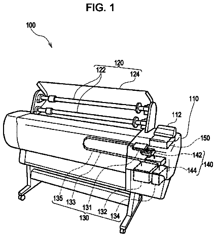
Sheet 1 of 15 from the published document. All sheets in the USPTO PDF
An apparatus includes: a first nozzles for ejecting a first fluid are lined up in a predetermined direction; a second nozzles for ejecting a second fluid are lined up in the predetermined direction; and a control unit performs an ejecting operation of ejecting fluid from the nozzles, wherein the control unit forms an image on a medium in one of a first mode of forming a main image with the first fluid and a second mode of forming the main image and a background image with the second fluid to be overlapped, forms the main image using a certain nozzle group in the first nozzles when the main image is formed in the first mode, and forms the main image using the same nozzle group as the certain nozzle group when the main image is formed in the second mode.
As a fluid ejecting apparatus, there is an ink jet printer (hereinafter, referred to as a printer) having a nozzle row in which nozzles for ejecting ink (fluid) onto a medium are arrayed in a predetermined direction. As the printer, a printer which repeatedly performs an operation of ejecting ink from the nozzles while moving the nozzle row in a movement direction intersecting the predetermined direction and an operation of transporting the medium in the predetermined direction is known. In addition, a printing apparatus for performing printing using white ink as well as color inks including cyan, magenta, and yellow colors is known (for example, refer to JP-A-2002-38063). In such a printer, for example, a background image printed with the white ink and a color image are overlapped to be printed, and thus a color image with good color developing property can be printed without being infl
1 of 15 drawing sheets so far from the published document, cropped to the drawing. Every sheet is in the USPTO PDF.
What the patent claimed, word for word. All of it is now free to use.
Priority is claimed under 35 U.S.C. .sctn.119 to Japanese Application No. 2009-284397 filed on Dec. 15, 2009, and No2010-086402 filed on Apr. 2, 2010, which is hereby incorporated by reference in its entirety.
The present invention relates to a fluid ejecting apparatus and a fluid ejecting method.
As a fluid ejecting apparatus, there is an ink jet printer (hereinafter, referred to as a printer) having a nozzle row in which nozzles for ejecting ink (fluid) onto a medium are arrayed in a predetermined direction. As the printer, a printer which repeatedly performs an operation of ejecting ink from the nozzles while moving the nozzle row in a movement direction intersecting the predetermined direction and an operation of transporting the medium in the predetermined direction is known.
In addition, a printing apparatus for performing printing using white ink as well as color inks including cyan, magenta, and yellow colors is known (for example, refer to JP-A-2002-38063). In such a printer, for example, a background image printed with the white ink and a color image are overlapped to be printed, and thus a color image with good color developing property can be printed without being influenced by a background color of the medium. Accordingly, there is a printer which performs printing by selecting one from a "white use mode" of printing a background image and a color image (main image) to be overlapped and a "color mode" of printing only a color image.
In a case where nozzles used for printing a color image in the white use mode are different from those in the color mode, due to a difference between the characteristics of the nozzles or a difference between optimal print patterns, there is a concern that image quality of the color image (main image) in one of the modes may be degraded compared to that in the other mode.
An advantage of some aspects of the invention is an enhancement in the quality of a main image regardless of mode.
According to an aspect of the invention, a fluid ejecting apparatus includes: a first nozzle row in which nozzles for ejecting a first fluid are lined up in a predetermined direction; a second nozzle row in which nozzles for ejecting a second fluid are lined up in the predetermined direction; and a control unit which repeatedly performs an ejecting operation of ejecting fluid from the nozzles while relatively moving relative positions of the first and second nozzle rows and a medium in a movement direction intersecting the predetermined direction and a moving operation of relatively moving the relative positions of the first and second nozzle rows and the medium in one direction of the predetermined direction, wherein the control unit forms an image on the medium in one of a first mode of forming a main image with the first fluid on the medium and a second mode of forming the main image and a background image with the second fluid to be overlapped on the medium, forms the main image using a certain nozzle group in the first nozzle row when the main image is formed in the first mode, and forms the main image using the same nozzle group as the certain nozzle group when the main image is formed in the second mode.
Further features of the invention will become apparent from the following description of the specification and the accompanying drawings.
The invention will be described with reference to the accompanying drawings, wherein like numbers reference like elements.
FIG. 1 is a block diagram of the entire configuration of a printer.
FIG. 2 is a perspective view of the printer.
FIG. 3 is a diagram illustrating an array of nozzles provided on a lower surface of a head.
FIG. 4 is a diagram for explaining print modes of the printer.
FIG. 5 is a diagram illustrating a printed example in a front print and white use mode.
FIG. 6 is a diagram illustrating a printed example in a rear print and white use mode.
FIG. 7 is a diagram illustrating an evaluation result of print patterns 1 to 5.
FIG. 8 is a diagram for explaining the print pattern 1.
FIG. 9 is a diagram for explaining the print pattern 2.
FIG. 10 is a diagram for explaining the print pattern 3.
FIG. 11 is a diagram for explaining the print pattern 4.
FIG. 12 is a diagram for explaining the print pattern 5.
FIG. 13 shows a print pattern table stored in a memory.
FIG. 14 is a diagram for explaining a setting flow of a print pattern according to Example 1.
FIG. 15 is a diagram for explaining a setting flow of a print pattern according to Example 2.
FIG. 16 is a diagram illustrating a printed example in the front print and white use mode.
FIG. 17 is a diagram illustrating a printed example in the rear print and white use mode.
Summary of Disclosure
At least the following features will become apparent from the description of the specification and the accompanying drawings.
That is, there is provided a fluid ejecting apparatus including: a first nozzle row in which nozzles for ejecting a first fluid are lined up in a predetermined direction; a second nozzle row in which nozzles for ejecting a second fluid are lined up in the predetermined direction; and a control unit which repeatedly performs an ejecting operation of ejecting fluid from the nozzles while relatively moving relative positions of the first and second nozzle rows and a medium in a movement direction intersecting the predetermined direction and a moving operation of relatively moving the relative positions of the first and second nozzle rows and the medium in one direction of the predetermined direction. The control unit forms an image on the medium in one of a first mode of forming a main image with the first fluid on the medium and a second mode of forming the main image and a background image with the second fluid to be overlapped on the medium, forms the main image using a certain nozzle group in the first nozzle row when the main image is formed in the first mode, and forms the main image using the same nozzle group as the certain nozzle group when the main image is formed in the second mode.
According to the fluid ejecting apparatus, the quality of the main image can be enhanced regardless of the mode, and the dot formation methods and medium transport control methods can be shared by the first and second modes, thereby simplifying the manufacturing process of the fluid ejecting apparatus.
In the fluid ejecting apparatus, the control unit forms an image on the medium in one of a first method of forming an image viewed from an image formation side and a second method of forming an image viewed from the reverse side to the image formation side on the medium. When the image is formed in the first method, in the second mode, the control unit forms the main image by a nozzle group of a part of the first nozzle row positioned on one direction side of the predetermined direction and forms the background image by a nozzle group of a part of the second nozzle row positioned closer to the other direction side of the predetermined direction than the nozzle group used for forming the main image, and in the first mode, the control unit forms the main image using the same nozzle group as the nozzle group in the first nozzle row for forming the main image in the second mode and in the first method. When the image is formed in the second method, in the second mode, the control unit forms the main image by the nozzle group of the part of the first nozzle row positioned on the other direction side of the predetermined direction and forms the background image by the nozzle group of the part of the second nozzle row positioned closer to the one direction side of the predetermined direction than the nozzle group for forming the main image, and in the first mode, the control unit forms the main image using the same nozzle group as the nozzle group in the first nozzle row for forming the main image in the second mode and in the second method.
According to the fluid ejecting apparatus, the dot formation methods, the medium transport control methods, and the like can be shared by each method (the first method and the second method) of the first mode and each method of the second mode, thereby simplifying the manufacturing process of the fluid ejecting apparatus.
In the fluid ejecting apparatus, a dot formation method of forming the main image in the first mode and in the first method is the same as a dot formation method of forming the main image in the second mode and in the first method, and a dot formation method of forming the main image in the first mode and in the second method is the same as a dot formation method of forming the main image in the second mode and in the second method.
According to the fluid ejecting apparatus, the manufacturing process of the fluid ejecting apparatus can be simplified.
In the fluid ejecting apparatus, the control unit forms an image on the medium in the first mode when the first method is selected, or forms an image on the medium in the first method when the first mode is selected.
According to the fluid ejecting apparatus, modes or methods of forming an image can be easily determined.
In the fluid ejecting apparatus, the control unit forms an image on the medium in the first mode and in the first method when the medium is an opaque medium.
According to the fluid ejecting apparatus, modes or methods of forming an image can be easily determined.
In the fluid ejecting apparatus, a dot formation method used when an image at a predetermined image quality level is formed on the medium in the first method and a dot formation method used when an image at the predetermined image quality level is formed on the medium in the second method are different from each other.
According to the fluid ejecting apparatus, an image formation time can be reduced according to methods while maintaining image quality.
In the fluid ejecting apparatus, a dot formation method of forming the main image in the first mode is the same as a dot formation method of forming the main image in the second mode.
According to the fluid ejecting apparatus, the manufacturing process of the fluid ejecting apparatus can be simplified.
In the fluid ejecting apparatus, the background image is formed using the nozzles in the first nozzle row disposed at the same position in the predetermined direction as the nozzle group in the second nozzle row for forming the background image.
According to the fluid ejecting apparatus, a background image with a desired color can be imaged.
In addition, there is provided a fluid ejecting method of a fluid ejecting apparatus which repeatedly performs an ejecting operation, while relatively moving relative positions of a first nozzle row in which nozzles for ejecting first fluid are lined up in a predetermined direction, a second nozzle row in which nozzles for ejecting second fluid are lined up in the predetermined direction, and a medium in a movement direction intersecting the predetermined direction, of ejecting fluid from the nozzles, and a moving operation of relatively moving the relative positions of the first and second nozzle rows and the medium in one direction of the predetermined direction, the fluid ejecting method including: setting one of a first mode of forming a main image with the first fluid on the medium and a second mode of forming the main image and a background image with the second fluid to be overlapped on the medium, and forming an image on the medium in the set mode; forming the main image using a certain nozzle group in the first nozzle row when the main image is formed in the first mode; and forming the main image using the same nozzle group as the certain nozzle group when the main image is formed in the second mode.
According to the fluid ejecting method, dot formation methods and medium transport control methods can be shared by the first and second modes, thereby simplifying the manufacturing process of the fluid ejecting apparatus.
Printing System
Hereinafter, an ink jet printer (hereinafter, a printer) is used as a fluid ejecting apparatus, and a printing system in which the printer is connected to a computer is exemplified for the description of exemplary embodiments.
FIG. 1 is a block diagram of the entire configuration of a printer 1. FIG. 2 is a perspective view of the printer 1. A computer 60 is connected to the printer 1 to communicate therewith and outputs print data to be used for printing an image by the printer 1 to the printer 1. In addition, installed in the computer 60 is a program (printer driver) for converting image data output from an application program into the print data. The printer driver may be recorded on a recording medium (a recording medium that the computer can read out) such as a CD-ROM or downloaded by the computer via the Internet.
A controller 10 is a control unit for controlling the printer 1. An interface unit 11 is used for receiving and transmitting data between the computer 60 and the printer 1. The CPU 12 is an arithmetic processing unit for controlling the entire printer 1. A memory 13 is used for providing an area for storing the programs of the CPU 12 and a work area. The CPU 12 controls each unit by a unit control circuit 14. In addition, a detector group 50 monitors the status in the printer 1, and the controller 10 controls each unit on the basis of the detection result.
A transporting unit 20 sends a medium S to a position where printing can be performed and transports the medium S by a predetermined transport amount in a transport direction (predetermined direction) during the printing.
A carriage unit 30 is used for moving a head 41 in a movement direction intersecting the transport direction and includes a carriage 31.
The head unit 40 is used for ejecting ink onto the medium S and includes the head 41. The head 41 is moved in the movement direction by the carriage 31. Provided on a lower surface of the head 41 is a plurality of nozzles which are ink ejecting portions, and each nozzle is provided with an ink chamber (not shown) containing ink.
FIG. 3 is a diagram illustrating an array of the nozzles provided on the lower surface of the head 41. In addition, the diagram illustrates the nozzles virtually viewed from an upper surface of the head 41. Formed on the lower surface of the head 41 are 5 nozzle rows each in which 180 nozzles are arrayed in the transport direction at a predetermined interval (a nozzle pitch D). As illustrated in FIG. 3, a black nozzle row K for ejecting black ink, a cyan nozzle row C for ejecting cyan ink, a magenta nozzle row M for ejecting magenta ink, a yellow nozzle row Y for ejecting yellow ink, and a white nozzle W for ejecting white ink are arrayed along the movement direction. Moreover, the 180 nozzles of each nozzle row are assigned with numbers in ascending order from a downstream side of the transport direction (#1 to #180).
In the printer 1, a dot formation process for forming dots on the medium by intermittently ejecting ink droplets from the head 41 which moves along the movement direction and a transport process (corresponding to a movement operation) for transporting the medium in the transport direction with respect to the head 41 are repeatedly performed. Accordingly, dots may be formed by the subsequent dot formation process at a different position on the medium from a position at which dots are formed by the preceding dot formation process, thereby printing a 2D image on the medium. In addition, an operation in which the head 41 moves once in the movement direction while ejecting ink droplets (corresponding to one dot formation process and the ejecting operation) is called a "pass".
Print Mode
FIG. 4 is a diagram for explaining print modes of the printer 1 according to this embodiment. The printer 1 forms an image on the medium in one of certain modes including a "color mode (corresponding to a first mode)" for printing only a color image (including a monochrome image) to be printed with 4-color ink (YMCK) on the medium, and a "white use mode (corresponding to a second mode)" for printing a background image with white ink and a color image to be overlapped on the medium. By providing the white background image as a background of the color image (corresponding to a main image) in the white use mode, an image with good color developing property can be printed, particularly when the medium is not white. In addition, when the medium is transparent, by printing the color image and the background image to be overlapped, it is possible to prevent the opposite side of the printed matter from becoming transparent.
Moreover, the printer 1 forms an image on the medium in one of certain modes including a "front print mode (a first method)" for printing a color image to be seen from a printed surface side and a "rear print mode (a second method)" for printing the color image to be seen from the medium side (the opposite side to the image formation side). That is, the printer 1 includes, as illustrated in FIG. 4, four print modes including a front print and color mode, a rear print and color mode, a front print and white use mode, and a rear print and white use mode.
In order to print only the color image on the medium in the color mode, the color image is directly printed on the medium in any of the front print mode and the rear print mode. In the white use mode, in order to print the color image and the background image to be overlapped, in the front print mode the background image is printed on a predetermined area of the medium in advance, and the color image is printed on the background image. On the contrary, in the rear print mode, the color image is printed on the predetermined area of the medium in advance, and the background image is printed on the color image.
FIG. 5 is a diagram illustrating a printed example in the front print and white use mode. FIG. 6 is a diagram illustrating a printed example in the rear print and white use mode. For the simplification of the description, in the figures, the number of nozzles that belong to one nozzle row is reduced to 14. In addition, the nozzle rows respectively ejecting four color inks (YMCK) are collectively referred to as a "color nozzle row Co (corresponding to the first nozzle row)". FIGS. 5 and 6 illustrate band printing. Band printing is a printing method in which band images formed in one pass are lined up in the transport direction and a raster line is not formed in another pass inside a raster line (a dot row along the movement direction) formed in any pass.
However, when the background image is printed using only the white ink, the color itself of the white ink used for printing the background image becomes the color of the background image. However, inks called white inks at the same time may exhibit slightly different tones of white color due to materials of the ink or the like. Therefore, there may be a case where a background image with a color that a user does not want may be printed due to the white ink being used. In addition, depending on the printed matter, there may be a case where a background image with a slightly chromatic color is desired instead of simply a white color. When a white medium is used, white media also exhibit different tones of white color depending on types of the media. Accordingly, when a background is printed on a white medium, if the white color of the background image is different from the white color of the medium, the background image becomes noticeable.
Therefore, in this embodiment, a background image (a background image with adjusted white color) with the desired white color is printed appropriately using a small amount of color ink (YMCK) as well as with the white ink. That is, when the background image is to be printed, at least one from among the color inks that can be ejected by the printer 1 may be used. For example, four color inks may be used, or two color inks may be used. As described above, as the background image is printed using the white ink and the color ink, in a case where the white ink has light color, the background image is printed with ink for cancelling out the color, thereby allowing the background image to approximate an achromatic color.
In addition, print data used for printing the background image with the desired white color by the printer 1 may be stored in the printer 1 in advance or may be generated by a printer driver. When the desired color of the background image is selected by the user through a monitor of the printer 1 or a screen of the computer, print data of the background image corresponding to the selected color may be generated.
In the front print and white use mode of FIG. 5, the background image is first printed on the predetermined area of the medium, and the color image is printed thereon. Therefore, half (#8.DELTA. to #14.DELTA.) of the nozzles in the white nozzle row W (corresponding to the second nozzle row) on an upstream side of the transport direction and half (#8 to #14) of the nozzles in the color nozzle row on the upstream side of the transport direction serve as use nozzles for printing the background image, and half (#1.circle-solid. to #7.circle-solid.) of the nozzles in the color nozzle row Co on the downstream side of the transport direction serve as use nozzles for printing the color image. In addition, in the front print and white use mode, ink is not ejected from half of the nozzles (#1 to #7) in the white nozzle row W on the downstream side of the transport direction. In addition, since FIG. 5 illustrates band printing, an amount of the medium transported once corresponds to a width in the transport direction of the image formed in one pass. In the white use mode, since two types of images are formed in one pass, an amount of the medium transported once corresponds to a width in the transport direction of the background image or the color image formed in one pass. Therefore, in FIG. 5, the amount of the medium transported once is a length "7D" of the half of the nozzle row (the total length of the seven nozzles).
That is, in the front print and white use mode, an operation of forming images using the use nozzles in the white nozzle row W on the upstream side of the transport direction, the use nozzles in the color nozzle row Co on the upstream side of the transport direction, and the use nozzles in the color nozzle row Co on the downstream side of the transport direction, and an operation of transporting the medium by only the transport amount 7D are repeatedly performed. As a result, the predetermined area of the medium is opposed to the use nozzles (#8 to #14) in the white nozzle row W and the color nozzle row Co on the upstream side of the transport direction, and the background image is printed on the predetermined area of the medium. Thereafter, as the medium is transported to the downstream side of the transport direction, the predetermined area of the medium is opposed to the use nozzles (#1 to #7) in the color nozzle row Co on the downstream side of the transport direction, and the color image is printed on the background image in the predetermined area of the medium.
On the contrary, in the rear print and white use mode, as illustrated in FIG. 6, half (#1.DELTA. to #7.DELTA.) of the nozzles in the white nozzle row W on the downstream side of the transport direction, half (#1 to #7) of the nozzles in the color nozzle row Co on the downstream side of the transport direction serve as use nozzles for printing the background image, and half (#8.circle-solid. to #14.circle-solid.) of the nozzles in the color nozzle row Co on the upstream side of the transport direction serve as use nozzles for printing the color image. In addition, the amount of the medium transported once is the length 7D of half of the nozzle row. As a result, the predetermined area of the medium is first opposed to the use nozzles (#8 to #14) in the color nozzle row Co on the upstream side of the transport direction, and the color image is printed on the predetermined area of the medium. Thereafter, as the medium is transported to the downstream side of the transport direction, the predetermined area of the medium is opposed to the use nozzles (#1 to #7) in the white nozzle row W and the color nozzle row Co on the downstream side of the transport direction, and the background image is printed on the color image in the predetermined area of the medium.
As described above, a position in the transport direction of the nozzles (.DELTA.) in the white nozzle row W for printing the background image and a position in the transport direction of the nozzles (O) in the color nozzle row Co for printing the same background image can be made to be the same. Then, in order to print the background image, white ink and color ink are ejected onto the predetermined area of the medium in the same pass. Consequently, the white ink and the color ink are mixed with each other, thereby reducing granularity of the background image.
The proportion of color ink used for constituting the background image is smaller than the proportion of white ink. Here, in order to reduce the granularity of the color ink in the background image, dots of the color ink may be dispersed as uniformly as possible. That is, a color ink density (dot density) per unit area of the background image is smaller than a white ink density (dot density) per unit area of the background image. Therefore, although the proportion of the color ink used for constituting the background image is smaller than the proportion of the white ink, in this embodiment, the number of nozzles in the white nozzle row W and the number nozzles in the color nozzle row Co, which are used for printing the background image, are equal to each other. That is, the background image is printed using the half of the nozzles that belong to the color nozzle row Co. However, the invention is not limited thereto, and the background image may be printed using nozzles at intervals from among the half of the nozzles in the color nozzle row Co that can be used for printing the background image.
In the white use mode as described above, the use nozzles for the image to be printed first from among the color image and the background image, may be set as the nozzles which are closer to the upstream side of the transport direction than the use nozzles for the image to be printed subsequently. Accordingly, the images may be printed in the order corresponding to the front print or the rear print mode. In addition, a pass in which the background image is printed on the predetermined area of the medium may be set to be different from a pass in which the color image is printed. In this case, a relatively long time to dry until the subsequent image is printed after the preceding image is printed can be acquired, thereby suppressing oozing of the image.
Suitable Print Pattern Per Image Quality Level
FIG. 7 is a diagram illustrating an evaluation result of print patterns 1 to 5 of adoption candidates of an image quality level 2. FIGS. 8 to 12 are diagrams for explaining the print patterns 1 to 5 of the adoption candidates of the image quality level 2. In the printer 1 according to this embodiment, the user may select one from among 3 types of print modes (image quality levels) including a "sharp mode", a "normal mode", and a "quick mode" depending on the use. Images with higher quality can be printed in the order of the sharp mode (image quality level 1), the normal mode (image quality level 2), and the quick mode (image quality level 3). On the other hand, the image can be performed at higher speed in the order of the quick mode, the normal mode, and the sharp mode. Therefore, the print patterns (corresponding to the printing method and the dot formation method) in the image quality levels 1 to 3 are different from each other.
The printer 1 can print a number of print patterns, and even when an image is printed at the same image quality level, a plurality of types of print patterns may be performed. For example, the printer 1 may perform the five print patterns 1 to 5 as the print patterns for printing the image at the image quality level 2 as illustrated in FIG. 7. In the print patterns 1 to 5 for performing printing at the same degree of image quality, image quality (slightly) varies due to characteristics of the head 41 (nozzles), transport characteristics of the medium, and characteristics of various components in the printer 1. Therefore, there may be a case where, even in the same type of printer as well as different types of printers, print patterns in which printing can be performed at highest image quality vary in the print patterns 1 to 5 in which printing is performed at the same degree of image quality. For example, from among the print patterns 1 to 5 in which an image is printed at the image quality level 2, image quality of the image printed in the print pattern 2 is highest in a printer 1, or image quality of the image printed in the print pattern 4 is highest in a different printer.
In this embodiment, in a manufacturing process of the printer 1, an optimal print pattern is determined for the printer 1 in each of the image quality levels 1 to 3. Here, as evaluation criteria for determining the optimal print pattern, as illustrated in FIG. 7, there are image quality of the printed image and print speed. In addition, the manufacturing process includes at least any one of a design process and a mass production process. Here, the optimal print pattern is determined depending on the differences between the image quality characteristics of individual printers 1. That is, the optimal print pattern is determined in the mass production process. However, the invention is not limited thereto, and the optimal print pattern may be determined depending on differences between image quality characteristics of types of the printers 1, that is, in the design process.
Hereinafter, a method of determining the optimal print pattern in the image quality level 2 will be exemplified. As described above, candidate print patterns of the image quality level 2 are 5 types of print patterns 1 to 5. First, the print patterns 1 to 5 will be described in detail.
FIG. 8 is a diagram for explaining the print pattern 1. In FIG. 8, a positional relationship of the color nozzle row Co between passes, and the number of nozzles that belong to the color nozzle row Co is set to 14. In addition, in the following description, printing in the front print and white use mode will be exemplified. In the front print and white use mode, as illustrated in FIG. 5, the half #1 to #7 of the nozzles on the downstream side of the transport direction from among the nozzles that belong to the color nozzle row Co serve as the use nozzles. Therefore, in FIG. 8, a type of printing using the color nozzles #1 to #7 is illustrated (numbers in circles in the figure denote nozzle numbers). The non-use nozzles #8 to #14 which are the half of the color nozzle row Co on the upstream side, and the white nozzle row W are not shown. In addition, the print pattern formed by the color nozzles and the print pattern formed by the white nozzles are the same.
In the print pattern 1, a single raster line is formed by a single nozzle. Therefore, as illustrated in FIG. 8, a plurality of the nozzles is not lined up in the movement direction. In addition, a print resolution in the transport direction is set to a resolution (for example, 540 dpi) which is three times a nozzle pitch D (for example, 180 dpi) of the color nozzle row Co. That is, two raster lines are printed in the raster line formed in one pass. To perform printing as described above, the amount of the medium transported once becomes a "repetition of 8D/3, 8D/3, and 5D/3". In the figures, since the number of nozzles that belong to a single nozzle row is reduced, the amount of the medium transported once is shortened. However, in actual fact, there are many nozzles that belong to a single nozzle row, so that according to this the actual medium transport amount is determined.
The front print and white use mode and the rear print and white use mode are different from each other in that (positions of) nozzles used in the color nozzle row Co are different; however, the number of nozzles used and the medium transport amount are the same if the print pattern is the same. Therefore, as illustrated in FIG. 8, the color nozzle #1 in the front print mode corresponds to the color nozzle #8 in the rear print mode, and the color nozzle #2 in the front print mode corresponds to the dolor nozzle #9 in the rear print mode. Therefore, the description of the rear print mode will be omitted.
FIG. 9 is a diagram for explaining the print pattern 2. In the print pattern 2, a part of a raster line is printed using two nozzles (so-called partial overlap printing). In the use nozzles #1 to #7 of the color nozzle row Co, two nozzles from among the two nozzles #1 and #2 at an end on the downstream side and the two nozzles #6 and #7 at an end on the upstream side are used for printing one raster line. In addition, the print resolution in the transport direction is the same as that of the print pattern 1. Accordingly, in the print pattern 2, the amount of the medium transported once is "5D/3".
As a result, for example, the two nozzles #6 and #1 may be allocated to a row area A on the medium on which the raster line is to be formed, and the one nozzle #3 may be allocated to a row area B on which another raster line is to be formed. In the area where two nozzles can be applied to a single row area, even though one nozzle is a defective nozzle having different ejection characteristics including an ejection amount or ejection direction different from design values, dots can be formed using the other nozzle. Therefore, it is possible to lessen and suppress the generation of white stripes on the image.
FIG. 10 is a diagram for explaining the print pattern 3. In the print pattern 3, the number of raster lines formed by two nozzles is increased compared to the print pattern 2. In the use nozzles #1 to #7 of the color nozzle row Co, two nozzles from among the three nozzles #1 to #3 at the end on the downstream side and the three nozzles #5 to #7 at the end on the upstream side are used for printing one raster line. In addition, the print resolution in the transport direction is the same as those of the print patterns 1 and 2, and the amount of the medium transported once in the print pattern 3 is "4D/3".
FIG. 11 is a diagram for explaining the print pattern 4. In the print pattern 4, all raster lines are formed by a plurality of the nozzles. Consequently, even when a nozzle in the color nozzle row Co is a defective nozzle, it is possible to suppress the generation of white stripes on the image. In addition, the print resolution in the transport direction is the same as those of the print patterns 1 to 3, and the amount of the medium transported once in the print pattern 4 is "2D/3". Since all raster lines are formed by the plurality of the nozzles in the print pattern 4, the amount of the medium transported once is relatively small, and from among the half #1 to #7 of the nozzles in the color nozzle row Co, there are nozzles that do not need to be used. For example, in FIG. 11, the nozzle #7 serves as the non-use nozzle.
In addition, when there are non-use nozzles due to the medium transport amount and the overlap number (the number of nozzles used for forming a single raster line), nozzles between the color nozzle row Co and the white use nozzle row W may serve as the non-use nozzles. In addition, a length in the transport direction of the area that the non-use nozzles belong to is an integral multiple of the medium transport amount. Accordingly, for the entire area of the image, a pass (a predetermined drying time) in which printing is not performed can be provided between the color image and the background image, thereby suppressing density unevenness of the image.
FIG. 12 is a diagram for explaining the print pattern 5. The print resolutions in the transport direction in the print patterns 1 to 4 are equal to each other and have a value that is three times the nozzle pitch D of the color nozzle row Co. On the other hand, in the print pattern 5, the print resolution in the transport direction is further increased to a resolution that is four times the nozzle pitch D of the color nozzle row Co. That is, three raster lines are printed in the raster line formed in one pass. In addition, in the print pattern 5, the partial overlap printing is also performed as in the print pattern 2. In the use nozzles of the color nozzle row Co, two nozzles from among the two nozzles #1 and #2 at the end on the downstream side and the two nozzles #6 and #7 at the end on the upstream side are used for printing one raster line. Accordingly, in the print pattern 5, the amount of the medium transported once is "5D/4".
In general, as the number of raster lines formed by a plurality of nozzles is increased or the print resolution is enhanced, the print speed is decreased, and image quality is improved. However, positions at which defective nozzles are included vary in printers 1. Therefore, even in the print patterns 2 and 3 in which parts of the raster line are printed by overlapping the plurality of nozzles, when the defective nozzles are incidentally allocated so that they do not overlap in the same row area, the print patterns 1 to 3 have substantially the same degree of image quality even though the print patterns 2 and 3 in which the partial overlap printing is performed have lower print speeds than that of the print pattern 1. In addition, when the printer 1 without defective nozzles selects a print pattern for printing one raster line with a plurality of nozzles or selects a print pattern with high print resolution, the print speed is unnecessarily lowered. In addition, due to characteristics of the transporting unit 20 of printer 1, transport characteristics (for example, a method of causing a transport error) of the medium vary. Then, connection or the like of the images in each print pattern is different depending on the printer 1, so that the optimal print patterns also vary.
That is, due to characteristics of the printer 1 (the head 41, the transporting unit 20, and the like), the optimal print pattern (a print pattern in which the image quality is as high as possible and the print speed is as fast as possible) varies in the print patterns 1 to 5 for performing printing at substantially the same degree of image quality. In addition, print patterns (dot formation methods) are different in that at least one of the medium transport amount, (the number or positions of) nozzles used for printing an image, the print resolution, the number of raster lines formed by the plurality of nozzles, the number of nozzles used for forming one raster line, and the like varies.
Here, in this embodiment, in order to determine the optimal print pattern from among the 5 types of print patterns 1 to 5, in the manufacturing process (inspection process), an inspector allows the printer 1 to print the 5 print patterns 1 to 5 (not shown) as test patterns in the front print and white used mode. That is, 5 test patterns in which color images are printed on the background image are formed. The inspector views the color images of the 5 test patterns on the printed surface side and evaluates image quality. In addition, although the background images are printed in the test patterns since the test patterns are printed in the white use mode, the image quality is evaluated for the color images.
The description continues in the full USPTO document.
About 7,085 words. The USPTO PDF has it with every drawing.
Fees are due 3.5, 7.5 and 11.5 years after grant. This patent expired on September 10, 2025, so the fee marked "not paid" was the one that went unpaid.
FLUID EJECTING APPARATUS AND FLUID EJECTING METHOD
Filed Dec 2010 · published Jun 2011Fluid ejecting apparatus and fluid ejecting method
Filed Dec 2010 · granted Sep 2013Earlier publications, parents and continuations. None of them can still be enforced, or this patent would not be listed.
Prior art cited by the examiner or applicant. Useful when you check your own idea for novelty.
Everything on this page comes from the documents linked above.