 Lapsed, fee not paid4 drawings
Software & Apps · US 9,998,550 B2
Network based service composition with variable conditions
Network based service composition with variable distance conditions may be provided.
US 9,998,563 B2 · Assignee: FUJITSU LIMITED · Inventors: Zhang; Qiong et al.
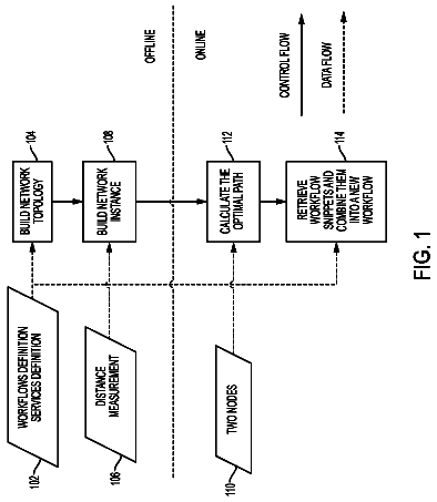
Sheet 1 of 19 from the published document. All sheets in the USPTO PDF
Systems and methods for performing vertex-centric service function chaining in multi-domain networks are disclosed. A resource orchestration framework of a multi-domain network may include vertices representing physical nodes and edges representing physical links in the network. A sole resource orchestrator (in a centralized system) or multiple resource orchestrators (each associated with a respective domain in a distributed system) may coordinate execution of a common compute function on multiple vertices to identify candidate service function chain solutions to a service function chain request. The request may specify a fixed-ordered chain or a flexible-ordered chain. The compute function may, during each of multiple supersteps, determine whether a partially mapped chain can be extended on a given vertex, send a controller message to a neighbor vertex with which it has a qualified link, or return a completed chain, which may be selected for execution, dependent on applicable policies.
Field of the Disclosure The present disclosure relates generally to network function virtualization and, more particularly, to systems and methods for performing vertex-centric service function chaining in multi-domain networks. Description of the Related Art Emerging network applications, such as cloud and big data, may involve joint consideration of IT resources residing within multiple domains within one or more data centers (DCs). Network function virtualization (NFV) can be used to virtualize network functions and migrate them from devices that are built for a single, specific purpose to multi-purpose virtual machines, which may reduce service deployment costs and improve service flexibility. As more service functions move to virtual machines in geographically distributed data centers and as more individually-managed Networks-on-Demand are enabled by software defined networking (SDN
1 of 19 drawing sheets so far from the published document, cropped to the drawing. Every sheet is in the USPTO PDF.
What the patent claimed, word for word. All of it is now free to use.
Field of the Disclosure
The present disclosure relates generally to network function virtualization and, more particularly, to systems and methods for performing vertex-centric service function chaining in multi-domain networks.
Description of the Related Art
Emerging network applications, such as cloud and big data, may involve joint consideration of IT resources residing within multiple domains within one or more data centers (DCs). Network function virtualization (NFV) can be used to virtualize network functions and migrate them from devices that are built for a single, specific purpose to multi-purpose virtual machines, which may reduce service deployment costs and improve service flexibility. As more service functions move to virtual machines in geographically distributed data centers and as more individually-managed Networks-on-Demand are enabled by software defined networking (SDN) technology, end-to-end network services may implement various mechanisms to coordinate resources across multi-domain networks. For example, a network service may traverse one or more consumer broadband networks, mobile backhaul networks, mobile packet core networks, and/or virtual private networks.
Traditional distributed routing protocols typically compute network paths without considering the availability of service functions and virtual machines at the individual network nodes. A hybrid architecture (e.g., one with geographically distributed orchestrators that replicate a global view of service functions, virtual machines, and networks) can lead to additional challenges, such as managing the global network state, maintaining the confidentiality of various network domains, and managing high computation complexity on a large-scale global view. An approach using path-computation element (PCE)-based multi-domain heuristics to for map virtual optical network requests would typically require a parent PCE to compute all possible inter-domain paths. Furthermore, mapping a single virtual link would typically require signaling along all possible inter-domain paths, which can result in significant signaling overhead for a very large number of paths in a large-scale network. Previously proposed virtual network mapping algorithms for multi-domain networks can be suitable for mapping service function chain (SFC) requests, but they typically require a centralized orchestrator to maintain a hierarchical topology for all domains in a multi-domain network.
In one aspect, a disclosed method is for identifying a qualified service function chaining solution in a multi-domain network. The method may include receiving, at a resource orchestrator, a service function chain request specifying a plurality of service functions to be performed on respective physical nodes in the multi-domain network, each node being represented as a vertex in a resource orchestration framework, and identifying one or more vertices at which a first one of the plurality of service functions is available. The method may also include, for a first one of the identified vertices, mapping the first identified vertex to the first one of the plurality of service functions in a candidate service function chain, determining that a second one of the plurality of service functions is available at a first neighbor vertex of the first identified vertex, where the first neighbor vertex resides in a different domain of the multi-domain network than the domain in which the first identified vertex resides, and mapping the first neighbor vertex to the second one of the plurality of service functions in the candidate service function chain to extend the candidate service function chain.
In any of the disclosed embodiments, the method may further include determining that a third one of the plurality of service functions is available at a second neighbor vertex of the first neighbor vertex, where the second neighbor vertex resides in a different domain of the multi-domain network than the domain in which the first neighbor vertex resides, and mapping the second neighbor vertex to the third one of the plurality of service functions in the candidate service function chain to further extend the candidate service function chain.
In any of the disclosed embodiments, mapping the first neighbor vertex to the second one of the plurality of service functions in the candidate service function chain may complete the candidate service function chain, and the method may further include returning the completed candidate service function chain to the resource orchestrator.
In any of the disclosed embodiments, the service function chain request may specify a fixed order for the plurality of service functions to be performed on the respective physical nodes in the multi-domain network, and the fixed order may specify that the first one of the plurality of service functions is to be performed prior to the second one of the plurality of service functions.
In any of the disclosed embodiments, the method may further include completing the candidate service function chain, and completing one or more other candidate service function chains. Completing each of the other candidate service function chains may include mapping a respective vertex in the resource orchestration framework to each of the plurality of service functions in the other candidate service function chain. The sets of mappings in the candidate service function chain and in each of the one or more other candidate service function chains may be different. The method may also include selecting, from among the candidate service function chain and the one or more other candidate service function chains, one or more service function chain solutions for execution. The selecting may be dependent on a service provider policy, a service provider constraint, or a requestor on whose behalf the service function chain request was received.
In any of the disclosed embodiments, the selecting may be dependent on one or more of: a total delay of a candidate service function chain, a total cost of a candidate service function chain, an overlapping of physical nodes in two of the candidate service function chains, an overlapping of physical links in two of the candidate service function chains, or a load balancing mechanism.
In any of the disclosed embodiments, the service function chain request may specify a flexible-ordering for the plurality of service functions to be performed on the respective physical nodes in the multi-domain network, and mapping the first identified vertex to the first one of the plurality of service functions in the candidate service function chain may include mapping the first identified vertex to a service function in a position other than the first position in the candidate service function chain.
In any of the disclosed embodiments, the method may further include completing the candidate service function chain, and completing a second candidate service function chain. Completing the second candidate service function chain may include mapping a respective vertex in the resource orchestration framework to each of the plurality of service functions in the second candidate service function chain. Vertices may be mapped to the plurality of service functions in the second candidate service function chain in a different order than the order in which they were mapped to the plurality of service functions in the candidate service function chain.
In any of the disclosed embodiments, the resource orchestrator may be a sole resource orchestrator for coordinating vertex-centric service function chaining in the multi-domain network.
In any of the disclosed embodiments, the resource orchestrator may be one of a plurality of resource orchestrators for coordinating vertex-centric service function chaining in the multi-domain network, each of which is associated with a respective domain in the multi-domain network, and each of which coordinates execution of a common compute function on vertices in its respective domain.
In any of the disclosed embodiments, identifying the one or more vertices at which a first one of the plurality of service functions is available may include the resource orchestrator sending a controller message to another one of the resource orchestrators, the other resource orchestrator being associated with the domain in which the first identified vertex resides, and the other resource orchestrator determining that the first one of the plurality of service functions is available at the first identified vertex. Mapping the first identified vertex to the first one of the plurality of service functions in the candidate service function chain may be performed by the first identified vertex.
In any of the disclosed embodiments, the first one of the identified vertices and the first neighbor vertex may be communicatively coupled to each other over a physical link, and determining that the second one of the plurality of service functions is available at the first neighbor vertex may include determining that the physical link meets qualifications specified for the service function chain request, sending a controller message including the candidate service function chain to the first neighbor vertex, and the first neighbor vertex determining that the second one of the plurality of service functions is available at the first neighbor vertex.
In another aspect, a disclosed resource orchestration framework in a multi-domain network may include a plurality of vertices, each of which represents a respective one of the physical nodes in the multi-domain network, and a resource orchestrator. The multi-domain network may include a plurality of network domains, each including one or more physical nodes. Each of the physical nodes may include circuitry or logic to perform a subset of a plurality of service functions supported in the multi-domain network. Each of the vertices in the resource orchestration framework may include a processor, and a memory that stores program instructions that when executed by the processor cause the processor to perform a compute function that is common among the vertices in the resource orchestration framework. The resource orchestrator may include a processor, and a memory that stores program instructions that when executed by the processor cause the processor to perform receiving a service function chain request specifying a plurality of service functions to be performed on respective ones of the physical nodes in the multi-domain network, identifying one or more vertices in the resource orchestration framework at which a first one of the plurality of service functions is available, and coordinating execution of two more supersteps of the common compute function on multiple ones of the plurality of vertices. During a first superstep of the common compute function, the execution of the common compute function on the first one of the identified vertices may include mapping the first identified vertex to the first one of the plurality of service functions in a candidate service function chain, and determining whether or not a physical link between the first identified vertex and a first neighbor vertex of the first identified vertex meets qualifications specified for the service function chain request. The first neighbor vertex may reside in a different domain of the multi-domain network than the domain in which the first identified vertex resides.
In any of the disclosed embodiments, during the first superstep, the execution of the common compute function on the first identified vertex may further include, in response to determining that a physical link between the first identified vertex and the first neighbor vertex meets qualifications specified for the service function chain request, providing the candidate service function chain to the first neighbor vertex. During a second superstep of the common compute function, the execution of the common compute function on the first neighbor vertex may include, in response to obtaining the candidate service function chain, determining whether or not the candidate service function chain can be extended at the first neighbor vertex.
In any of the disclosed embodiments, during the second superstep, the execution of the common compute function on the first neighbor vertex may further include determining that a second one of the plurality of service functions is available at the first neighbor vertex, and mapping the first neighbor vertex to the second one of the plurality of service functions in the candidate service function chain to extend the candidate service function chain.
In any of the disclosed embodiments, during the second superstep, the execution of the common compute function on the first neighbor vertex may further include determining whether or not a physical link between the first neighbor vertex and a second neighbor vertex of the first neighbor vertex meets qualifications specified for the service function chain request. The second neighbor vertex may reside in a different domain of the multi-domain network than the domain in which the first neighbor vertex resides. During the second superstep, the execution of the common compute function on the first neighbor vertex may also include, in response to determining that the physical link between the first neighbor vertex and the second neighbor vertex meets qualifications specified for the service function chain request, providing the extended candidate service function chain to the second neighbor vertex.
In any of the disclosed embodiments, during the second superstep, the execution of the common compute function on the first neighbor vertex may further include determining that the mapping of the first neighbor vertex to the second one of the plurality of service functions in the candidate service function chain completes the candidate service function chain, and providing the completed candidate service function chain to the resource orchestrator.
In any of the disclosed embodiments, when executed by the processor of the resource orchestrator, the program instructions stored on the memory of the resource orchestrator cause the processor to perform selecting, from among the completed candidate service function chain and one or more other completed candidate service function chains, one or more service function chain solutions for execution. The selection may be dependent on a service provider policy, a service provider constraint, or a requestor on whose behalf the service function chain request was received.
In any of the disclosed embodiments, the resource orchestrator may be a sole resource orchestrator for coordinating vertex-centric service function chaining in the multi-domain network.
In any of the disclosed embodiments, the resource orchestration framework may include a plurality of resource orchestrators, including the resource orchestrator, each of which is associated with a respective domain in the multi-domain network, and each of which coordinates the execution of the two more supersteps of the common compute function on vertices in its respective domain.
For a more complete understanding of the present invention and its features and advantages, reference is now made to the following description, taken in conjunction with the accompanying drawings, in which:
FIG. 1 illustrates selected elements of a distributed resource orchestration framework, according to at least some embodiments;
FIG. 2 is a block diagram illustrating selected elements of a multi-domain network for providing end-to-end services, according to one embodiment;
FIG. 3 is a network diagram illustrating selected elements of multiple distributed network domains, according to one embodiment;
FIG. 4 illustrates a distributed resource orchestration architecture, including communication channels (or links) between respective resource orchestrators of different domains, according to one embodiment;
FIG. 5 depicts an abstraction of an example SFC request, according to one embodiment;
FIGS. 6A and 6B illustrate an example mapping between an SFC request specifying a flexible-ordered service function chain and six possible fixed-ordered chains, any of which, if found, would satisfy this request, according to one embodiment;
FIGS. 7A and 7B illustrate selected elements of an example method for performing a compute( ) function, according to one embodiment;
FIGS. 8A-8J illustrate an example of vertex-centric distributed computing for generating one or more candidate solutions to a service function chain request, according to one embodiment;
FIG. 9 is a flow diagram illustrating selected elements of a method for performing a vertex-centric distributed algorithm to identify all qualified solutions for a service function chain request in a multi-domain network, according to one embodiment;
FIG. 10 is a flow diagram illustrating selected elements of a method for satisfying a service function chain request, according to one embodiment;
FIG. 11 is a block diagram of selected elements of an example network element, according to at least some embodiments; and
FIGS. 12A-12C illustrate selected results of simulations of the vertex-centric computations for identifying all qualified SFC solutions in a multi-domain network described herein, according to one embodiment.
In the following description, details are set forth by way of example to facilitate discussion of the disclosed subject matter. It should be apparent to a person of ordinary skill in the field, however, that the disclosed embodiments are exemplary and not exhaustive of all possible embodiments.
Throughout this disclosure, a hyphenated form of a reference numeral refers to a specific instance of an element and the un-hyphenated form of the reference numeral refers to the element generically or collectively. Thus, as an example (not shown in the drawings), widget “12-1” refers to an instance of a widget class, which may be referred to collectively as widgets “12” and any one of which may be referred to generically as a widget “12”. In the figures and the description, like numerals are intended to represent like elements.
As will be described herein, a distributed resource orchestration framework is disclosed that provides a scalable vertex-centric distributed approach for identifying all qualified service function chain (SFC) solutions in a multi-domain network. In some embodiments, the distributed resource orchestration framework disclosed herein may apply vertex-centric distributed processing approach that enables different vertices to exchange information about possible SFC solutions iteratively using controller messages until all possible solutions have been identified. In some embodiments of the distributed resource orchestration framework disclosed herein, each domain resource orchestrator managing the resources of a network domain may send messages to each vertex in its network domain, and the domain resource orchestrators may communicate with each other using controller messages. Simulation results have demonstrated superior efficiency and scalability for computing a large SFC request when compared to a centralized algorithm.
Turning now to the drawings, FIG. 1 illustrates selected elements of a distributed resource orchestration framework, according to at least some embodiments. More specifically, FIG. 1 illustrates an example embodiment of a network domain 100 , which is based on vertices that are individual network elements (NE). In FIG. 1 , network domain 100 is shown including domain-specific resource orchestrator 108 , and physical network 110 . In some embodiments, physical network 110 may be an underlying optical network, such as an optical transport network (OTN) or a flexible optical data plane (e.g., flexible transceivers) configured to adjust the bandwidth of connections.
In FIG. 1 , resource orchestrator 108 may manage or coordinate the use of resources within network domain 100 , shown comprising multiple network elements 112 . Network elements 112 may represent various types of network functionality, such as switches, routers, etc., and may include hardware to interconnect various types of physical interfaces. Network domain 100 comprises network element NE_A 112 - 1 , network element NE_B 112 - 2 , network element NE_C 112 - 3 , network element NE_D 112 - 4 , network element NE_E 112 - 5 , and network element NE_F 112 - 6 , along with connections between the network elements that may have different distances. Thus, network domain 100 may represent a network topology for a single network domain, the use of whose resources are coordinated by resource orchestrator 108 . Note that, in some embodiments, various network management functions for network domain 100 other than those provided by resource orchestrator 108 may be provided by a dedicated (e.g., domain-specific) SDN controller (not shown). When larger networks include multiple network domains, each individual network domain may be managed by a respective SDN controller.
As disclosed in further detail herein, network domain 100 may be included in a multi-domain network that uses a distributed processing approach and in which controller messages are exchanged between a plurality of resource orchestrators and/or network controllers, such as resource orchestrator 108 and/or an SDN controller, each of which is associated with a respective one of a plurality of network domains, such as physical network 110 . As described herein, the resource orchestrators may work collaboratively to execute an SFC in the multi-domain network, which may include identifying all possible SFC solutions, selecting one or more of the possible SFC solutions for execution (e.g., dependent on user preferences or various policies), and configuring the physical resources of various network nodes to implement the selection solution(s).
As previously noted, network function virtualization (NFV) may be used to virtualize network functions and migrate them from devices that are built for a single, specific purpose to multi-purpose virtual machines on commercial off-the-shelf servers, which may reduce service deployment costs and improve service flexibility. In systems that implement NFV, in order to provide an end-to-end network service, virtual network functions (VNFs) may need to be invoked in a sequential order, referred to as a service function chain (SFC). Service function chaining may involve configuring and/or allocating various virtual machines (VMs) to run these virtualized network functions, and may also involve steering traffic across one or more networks. For example, a traffic flow may be steered through a number of virtual network functions (VNFs) or service functions (SFs) in a specific order based on the service provider's policies and/or on user preferences. In some embodiments of the distributed resource orchestration frameworks described herein, service function chaining may be supported by the application of resource orchestration. For example, in some embodiments, a plurality of resource orchestration elements, referred to herein as resource orchestrators, may collectively and individually manage and coordinate the use of various resources (including service functions, virtual machines, and networks) at each data center, as well as the associated network resources to interconnect the VNFs. With the migration of VNFs to VMs in geographically distributed datacenters and the rollout of SDN controlled on-demand connectivity in IP/OTN networks, distributed resource orchestration across multi-domain networks, as described herein, may be highly beneficial for providing end-to-end network services. For example, a network service may span across multiple networks such as consumer broadband, mobile backhaul, mobile packet core, and/or virtual private networks (including, e.g., networks implemented on the 1Finity™ platform from Fujitsu Network Communications Inc.).
In various embodiments of the present disclosure, a large-scale multi-domain network may include many different domains, and these domains may have different network technologies, different vendors, different administration, different types of resources, and/or different virtualized networks. These domains may include domains in which reside Internet of Things (IoT) devices, computing resources, storage resources, and/or different types of service functions (including access service functions, metro service functions, and/or core service functions). In at least some embodiments, these multi-domain networks may preserve confidentiality among domains and improve scalability for service providers. In at least some of the multi-domain orchestration architectures described herein, each domain may be controlled by a local orchestrator, and vertex-centric distributed computing among the orchestrators may provide for end-to-end resource allocation.
FIG. 2 is a block diagram illustrating selected elements of a multi-domain network for providing end-to-end services, according to one embodiment. In this example embodiment, multi-domain network 200 includes four domains, shown as domains 210 , 220 , 230 , and 240 . Each of these domains may include one or more nodes (vertices), at least some of which may implement one or more service functions using the resources within that domain. The first domain, domain 210 , represents the Internet of Things (IoTs), various devices of which may issue service function chain requests. Three such devices are illustrated in FIG. 2 as devices 211 , 212 , and 213 , although any number of devices may be included in domain 210 , in different embodiments. In this example embodiment, the second domain, domain 220 , represents one or more data centers or other entities that provide access services that may be included in a service function chain. Three such services are illustrated in FIG. 2 as services 221 , 222 , and 223 , although any number of devices may be included in domain 220 , in different embodiments.
In this example embodiment, the third domain, domain 230 , represents one or more data centers or other entities that provide computing and/or storage services that may be included in a service function chain. Three such services are illustrated in FIG. 2 as services 231 , 232 , and 233 , although any number of devices may be included in domain 230 , in different embodiments. In this example embodiment, the fourth domain, domain 240 , represents one or more data centers or other entities that provide core service functions that may be included in a service function chain. Three such services are illustrated in FIG. 2 as core service functions 241 , 242 , and 243 , although any number of devices may be included in domain 240 , in different embodiments.
In the example illustrated in FIG. 2 , device 211 within domain 210 has issued a service function chain request 214 , which includes at least one access service, one computing or storage service, and one core service function. More specifically, service function chain request 214 specifies a service function chain that includes an access service function 223 (which is available on one of the nodes/vertices within domain 220 ), a computing or storage service function 232 (which is available on one of the nodes/vertices within domain 230 ), and a core service function 243 (which is available on one of the nodes/vertices within domain 240 ).
As described in detail herein, in various embodiments, the systems and method described herein for performing vertex-centric distributed computing to identify all qualified service function chain (SFC) solutions for an SFC request may be applied in systems that include network function virtualization, mobile edge computing, and/or IoTs with data analytics, and in which traffic traverses a sequence of service function instances across multiple domains.
In at least some embodiments of the present disclosure, each domain in a multi-domain network may include physical nodes and IP/OTN links. In at least some embodiments, a respective resource orchestrator may be associated with each network domain to manage all the physical nodes and links within its domain. In some embodiments, each physical node may include network elements (e.g., OTN switch, router) and/or compute servers and storage elements (e.g., datacenters) capable of invoking a subset of service functions selected from a catalog of service functions. Some examples of the service functions provided in these multi-domain networks include firewalls, deep packet inspection (DPI), network address translation (NAT), load balancers, and parental control functions. In one example, a service function chain may include a firewall, a deep packet inspection (DPI) service function, a parental control service function, and an anti-virus service function, each of which may be provided by nodes in a different network domain. In another example, a service function chain may include a network address translation (NAT) service function between two other types of service functions and/or between other service functions and an internet access service function, each of which is provided by nodes in a different network domain.
Referring now to FIG. 3 , selected elements of multiple distributed network domains are shown as a network diagram. In this example embodiment, the distributed network domains represent an exemplary embodiment of a multi-domain network 300 in which the use of resources for satisfying an SFC request is coordinated by a respective plurality of resource orchestrators 108 , such as those illustrated in FIG. 1 and described herein. Although the distributed network domains within multi-domain network 300 are shown as a specific network topology, it will be understood that various different types and sizes of networks and different numbers of network domains may be used with the network service computation system disclosed herein. Note that the distributed network domains within multi-domain network 300 are shown as a schematic illustration and are not drawn to scale.
In FIG. 3 , multi-domain network 300 includes a plurality of domains 110 , each comprised of individual vertices. A vertex may represent any of a variety of network nodes, such as a switch, a router, a network element, a data center, a sub-network, a sub-domain, among others. Thus, each vertex may be enabled to provide network connectivity to other vertices, as well as computational resources, such as for providing network services and supporting network applications. As shown, a connection link is provided between vertices and is labeled in FIG. 3 with an integer value representing a relative path distance for the connection link. This relative path distance may represent a delay between the vertices or other edge information (e.g., bandwidth), in other embodiments. It is noted that the connection links may be intra-domain and inter-domain.
The vertices in multi-domain network 300 represent a reachable network of vertices that may provide potential paths between a source vertex S and a destination vertex D. In this example, each domain has a local orchestrator 108 . For example, resource orchestrator 108 -A may coordinate the use of resources within domain 110 -A, which includes source vertex S, and vertices A1, A2, and A3; resource orchestrator 108 -B may coordinate the use of resources within domain 110 -B, which includes vertices B1, B2, B3, B4, B5, B6, and B7; resource orchestrator 108 -C may coordinate the use of resources within domain 110 -C, which includes vertices C1, C2, C3, and destination vertex D; and resource orchestrator 108 -D may coordinate the use of resources within domain 110 -D, which includes vertices D1, D2, and D3. In some embodiments of the distributed network domains shown within multi-domain network 300 , each resource orchestrator 108 (and/or an SDN controller for the domain) may communicate with vertices in its own respective domain 110 , while the vertices may refrain from communicating with each other.
In some embodiments, when computing service function chaining requests, each vertex (node) may send and receive messages inside a compute function to and from its vertex neighbors. For example, vertex (node) A1 has three edges, as it has three vertex neighbors that it can communicate with, and a common compute function. Vertex A1 may also have node information indicating, for example, the number of compute resources available on the node, the number of storage resources available on the node, the vertex ID for the node, and the service functions that are implemented and available on the node. In at least some embodiments, the resource orchestrators associated with different domains may be interconnected via control channels for communication to compute requests (e.g., service function chaining requests), based on the vertex-centric distributed processing described herein.
In at least some embodiments, the resource orchestrators (such as various ones of the resource orchestrators 108 illustrated in FIGS. 1 and 3 ) may communicate with each other and may be networked together using any suitable topology, such as a mesh, a ring, a star, or a bus, among others. Similarly, SDN controllers for the domains may communicate with each other and may be networked together using any suitable topology, such as a mesh, a ring, a star, or a bus, among others. In some embodiments, the communication among resource orchestrators 108 and/or among SDN controllers may employ a sideband network channel, or other network connection for management purposes, that does not otherwise interfere with the network connections between vertices, which may represent a payload network offered as a commercial service to customers by a service provider.
In at least some embodiments, the resource orchestrators (such as various ones of the resource orchestrators 108 illustrated in FIGS. 1 and 3 ) may send messages to each other to compute a final result for a distributed computation to solve a service function chain request. In such embodiments, each resource orchestrator may maintain a logical representation of the physical infrastructure of its own domain, where the vertices in the resource orchestration architecture represent the physical nodes in that domain. In at least some embodiments, in addition to maintaining vertex information (such as the node information described above), each vertex may also maintain information about its incoming and outgoing edges, and a common compute function, which is user-defined function. In at least some embodiments, for distributed computing among orchestrators, a computation may be broken down into iterations, called supersteps. In each superstep, each orchestrator may coordinate the execution of the compute functions of each vertex within its domain.
FIG. 4 illustrates a distributed resource orchestration architecture 400 , including the communication channels (or links) between the respective resource orchestrators of the different domains illustrated in FIG. 3 . In this example, the link between resource orchestrator 108 -A (which coordinates the use of resources within domain 110 -A) and resource orchestrator 108 -B (which coordinates the use of resources within domain 110 -B) is shown as link 406 . Similarly, the link between resource orchestrator 108 -A and resource orchestrator 108 -C (which coordinates the use of resources within domain 110 -C) is shown as link 404 ; the link between resource orchestrator 108 -A and resource orchestrator 108 -D (which coordinates the use of resources within domain 110 -D) is shown as link 402 ; the link between resource orchestrator 108 -B and resource orchestrator 108 -D is shown as link 410 ; the link between resource orchestrator 108 -C and resource orchestrator 108 -D is shown as link 408 ; and the link between resource orchestrator 108 -B and resource orchestrator 108 -C is shown as link 412 .
In the example illustrated in FIG. 3 and FIG. 4 , there are four network domains, and each network domain may include multiple physical nodes and optical transport network (OTN) overlay links. Each physical node may be a switch, router, or data center that includes one or more virtual machines and that is capable of invocating a set of service functions. For example each physical node may be capable of providing a firewall, deep packet inspection (DPI), a WAN optimization controller (WOC), customer premises equipment (CPE), a provider edge (PE) or, in general, any type of service function.
In various embodiments of the present disclosure, a distributed resource orchestration framework and a vertex-centric distributed algorithm may be employed for finding all qualified SFCs in multi-domain networks. In some embodiments, after identifying all qualified chains, one or more SFCs may be selected for execution based on any suitable criteria. For example, an SFC may be selected for execution that best reflects user preferences for resource usage or other policy decisions. In another example, the lowest-cost disjoint SFC may be selected (e.g., to address protection concerns). In yet another example, multiple parallel SFCs may be selected for execution, according to a user preference or an applicable SFC selection policy.
In at least some embodiments, an SFC request may include information specifying the following request elements: the service functions to be performed, the resources required to perform those service functions (e.g., the required number of virtual machines and/or storage resources), and delay or bandwidth requirements for the links between the nodes on which the different service functions in the chain are to be performed.
FIG. 5 depicts an abstraction of an example SFC request 500 , according to one embodiment. In this example, to satisfy SFC request 500 , the distributed resource orchestration mechanism may need to identify a first node 502 that includes n.sub.1 virtual machines (VMs) and can perform a first service function, ƒ.sub.1; a second node 504 that includes n.sub.2 virtual machines (VMs) and can perform a second service function, ƒ.sub.2; and a third node 506 that includes n.sub.3 virtual machines (VMs) and can perform a third service function, ƒ.sub.3. In addition, the distributed resource orchestration mechanism may need to verify that the link between node 502 and node 504 meets a first set of bandwidth and/or delay requirements 508 (e.g., BW.sub.1 and/or delay.sub.1), and that the link between node 504 and node 506 meets a second set of bandwidth and/or delay requirements 510 (e.g., BW.sub.2 and/or delay.sub.2).
In contrast to other types of virtual network requests, SFC requests may include two unique characteristics: they may be more linear in topology, and they may be flexible in terms of the order in which the service functions are executed, in some cases. Based on these characteristics of SFC requests, the distributed algorithm described herein may apply a vertex-centric distributed computing approach to solve service function chaining in multi-domain networks. In some embodiments, multiple service functions in an SFC can be mapped to a single physical node.
FIGS. 6A and 6B illustrate an example mapping between an SFC request specifying a flexible-ordered service function chain, ƒ.sub.1*ƒ.sub.2*ƒ.sub.3 (shown in FIG. 6A ) and six possible fixed-ordered chains, any of which, if found, would satisfy this request. These six fixed-ordered chains are shown in FIG. 6B as ƒ.sub.1⋅ƒ.sub.2⋅ƒ.sub.3, ƒ.sub.1⋅ƒ.sub.3⋅ƒ.sub.2, ƒ.sub.2⋅ƒ.sub.1⋅ƒ.sub.3, ƒ.sub.2⋅ƒ.sub.3⋅ƒ.sub.1, ƒ.sub.3⋅ƒ.sub.1⋅ƒ.sub.2, and ƒ.sub.3⋅ƒ.sub.2⋅ƒ.sub.1. In these figures, the symbol “*” between functions denotes a flexible ordering and the symbol “⋅” between functions denotes a fixed order.
The description continues in the full USPTO document.
About 6,063 words. The USPTO PDF has it with every drawing.
Fees are due 3.5, 7.5 and 11.5 years after grant. This patent expired on June 12, 2026, so the fee marked "not paid" was the one that went unpaid.
VERTEX-CENTRIC SERVICE FUNCTION CHAINING IN MULTI-DOMAIN NETWORKS
Filed Jun 2016 · published Apr 2017Vertex-centric service function chaining in multi-domain networks
Filed Jun 2016 · granted Jun 2018Earlier publications, parents and continuations. None of them can still be enforced, or this patent would not be listed.
Prior art cited by the examiner or applicant. Useful when you check your own idea for novelty.
Everything on this page comes from the documents linked above.


