Field of the invention
The present invention is generally related to control systems and, more particularly, to mechanisms for dynamic device discovery for servers binding to multiple master controllers.
Background of the invention
Many systems, such as control systems, monitoring systems, and the like (collectively referred to herein as control systems), exist that allow the discovery of devices in the control system. However, contemporary mechanisms utilize discovery protocols that allow a device to bind to only a single master.
Conventional discovery and static binding routines require an administrator to make an explicit, manual choice of which master controller a device is bound. Some mechanisms provide an auto-bind option that facilitates a master controller to automatically bind to any device which matches a dynamic application device maintained by the master controller. However, contemporary auto-bind mechanisms may cause catastrophic, undefined results when multiple master controllers attempt to bind to the same physical device, e.g., physical devices that are not configured to be bound to multiple master controllers. Accordingly, static binding mechanisms are preferred in conventional systems when multiple master controllers are listening to the same multicast address for a common device type.
Numerous systems exist, such as Remote Monitoring Systems (RMSs), which include servers that must bind to multiple master controllers. Static binding mechanisms are typically employed if multiple masters monitor a common multicast address to avoid binding of devices to multiple controllers even if servers are deployed that must bind to multiple masters. Consequently, an administrator must disadvantageously manually bind the servers to each of the master controllers.
Therefore, what is needed is a device discovery mechanism that allows servers to automatically bind to multiple master controllers without collisions, thereby overcoming the need to manually bind each master controller.
Summary of the invention
The present invention provides a system, method, and computer readable medium for dynamic device discovery and binding of servers to multiple master controllers. A device discovery beacon that includes a device Type Flag may be broadcast by a dynamic physical device. If the dynamic physical device comprises a server that is configured to bind to multiple master controllers, the dynamic physical device sets the value of the device Type Flag to indicate the dynamic physical device comprises a server. On detection of the beacon, a master controller configured according to disclosed embodiments may evaluate the device Type Flag. Upon determining the device Type Flag indicates the dynamic physical device comprise a server, the master controller may load a device Module for the dynamic physical device and commence communications with the dynamic physical device. In this instance, the master controller advantageously does not broadcast a binding notification thereby allowing other master controllers to bind with the same dynamic physical device.
In one embodiment of the disclosure, a method of binding a system server device to a controller is provided. The method includes receiving, by a first master controller, a first device discovery beacon from a first system server device, evaluating the beacon for inclusion of a device type flag, determining the beacon includes the device type flag, evaluating a value of the device type flag, determining the value indicates the first system server device comprises a server configured to bind to multiple master controllers, and loading, by the first master controller, an instance of a device module associated with the first system server device responsive to determining the value indicates the device comprises a server configured to bind to multiple master controllers.
In a further embodiment of the disclosure, a computer-readable medium having computer-executable instructions for execution by a processing system, the computer-executable instructions for binding a system server device to a controller is provided. The computer-readable medium comprises instructions that, when executed, cause the processing system to receive, by a first master controller, a first device discovery beacon from a first system server device, evaluate the beacon for inclusion of a device type flag, determine the beacon includes the device type flag, evaluate a value of the device type flag, determine the value indicates the system server device comprises a server configured to bind to multiple master controllers, load, by the first master controller, an instance of a device module associated with the first system server device responsive to determining the value indicates the device comprises a server configured to bind to multiple master controllers, and commence communication and control of the first system server device by the first master controller responsive to loading the instance of the device module.
In a further embodiment of the disclosure, a system for binding a control system device to a controller is provided. The system comprises a first dynamic physical device comprising a server configured to bind to multiple master controllers, a first master controller communicatively coupled with the first dynamic physical device and having a first instance of a dynamic application device corresponding to the first dynamic physical device, and a second master controller communicatively coupled with the first dynamic physical device and having a second instance of the dynamic application device corresponding to the first dynamic physical device. The first dynamic physical device broadcasts a first device discovery beacon including a device type flag having a value that indicates the first dynamic physical device comprises a server. The first master controller and the second master controller receive the first device discovery beacon and respectively evaluate the device type flag value. The first master controller loads a first instance of a device module associated with the first dynamic physical device responsive to determining the value indicates the first dynamic physical device comprises a server, and the second master controller loads a second instance of the device module responsive to determining the value indicates the first dynamic physical device comprises a server.
Brief description of the drawings
Aspects of the present disclosure are best understood from the following detailed description when read with the accompanying figures, in which:
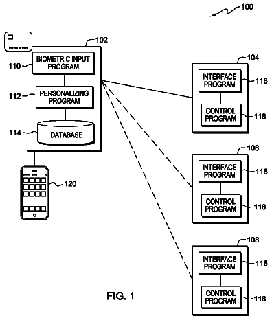
FIG. 1 is a simplified top-level block diagram of a control system configuration according to an embodiment of the present invention;
FIG. 2 is a block diagram illustrating the components of a master controller according to an embodiment of the present invention;
FIG. 3 is a block diagram illustrating a standard interface device controller configuration according to an embodiment of the present invention;
FIG. 4 is a block diagram illustrating another standard interface device controller configuration according to an embodiment of the present invention;
FIG. 5 is a flow chart illustrating command processing using a standard interface device controller according to an embodiment of the present invention;
FIG. 6 is a block diagram illustrating a control system configuration interconnecting two disparate protocols according to an embodiment of the present invention;
FIG. 7 is a block diagram illustrating the components of a dynamic device detection application according to an embodiment of the present invention;
FIG. 8A is a flow chart generally illustrating dynamic device processing according to an embodiment of the present invention;
FIG. 8B is a flow chart illustrating dynamic IP device processing according to an embodiment of the present invention;
FIG. 8C is a flow chart illustrating dynamic serial device processing according to an embodiment of the present invention; and
FIGS. 9-14 illustrate an exemplary user interface and computer program for managing dynamic devices according to an embodiment of the present invention.
FIG. 15 is a diagrammatic representation of a control system configuration that provides for device control and monitoring and in which a dynamic device discovery routine implemented in accordance with disclosed embodiments may be deployed;
FIG. 16 depicts a diagrammatic representation of a contemporary device discovery and binding mechanism;
FIG. 17 is a diagrammatic representation of a signaling flow of a contemporary device discovery and static binding routine;
FIG. 18 depicts a diagrammatic representation of a device discovery and binding mechanism implemented in accordance with disclosed embodiments;
FIG. 19 depicts a diagrammatic representation of a signaling flow of a device discovery and binding routine that facilitates binding a server to multiple masters in accordance with an embodiment; and
FIG. 20 is a flowchart that depicts a device discovery and binding routine that facilitates binding a server to multiple masters in accordance with an embodiment.
Detailed description of the invention
It is to be understood that the following disclosure provides many different embodiments or examples for implementing different features of various embodiments. Specific examples of components and arrangements are described below to simplify the present disclosure. These are, of course, merely examples and are not intended to be limiting.
I. Duet Overview
Referring to FIG. 1 , a simplified top-level block diagram of a control system 10 configuration according to an embodiment of the present invention is shown. One or more devices 16 a - 16 n in the control system 10 can send control commands to and/or receive control messages from a master controller 40 on one or more control area networks 12 and 12 a . The present invention includes common application programming interfaces (APIs) that are used to represent the one or more devices 16 a - 16 n . The one or more devices 16 a - 16 n may be wholly unrelated in technology. Therefore, the common APIs represent the one or more devices 16 a - 16 n by defining a structure whereby different device technologies are grouped together into classes by common operation and/or functionality from the general to the specific. Thus, different classes are used to represent different groups and subgroups of technology for the one or more devices 16 a - 16 n . For instance, a class may represent all home entertainment devices, such as VCR, television, CD and DVD. Another class may represent specifically all brands of VCRs and another class may represent a particular brand/vendor of the VCR. The present invention recognizes that even devices that are wholly unrelated in technology may share common functionality. For instance, a DVD, TIVO, VCR, LD and Cassette Deck each share the functional ability of playing some form of media. Thus, common APIs are used to abstract the operational and/or functional capabilities of the one or more devices 16 a - 16 n , such that applications may communicate with the one or more devices 16 a - 16 n without concern for the underlying technology and/or proprietary protocols of the devices.
Control system 10 includes one or more control area networks (CAN) 12 and 12 a . Control area networks 12 and 12 a are local area networks used to interconnect a variety of devices 16 a - 16 n , user interface device 14 and master controller 40 . Optionally, the control area network may be used to interconnect other networks 18 and 20 , such as a proprietary network, local area network, an Intranet, or the Internet. Control area networks 12 and 12 a may be used to interconnect multiple disparate protocols. For instance, a Microsoft UPnP (Universal Plug and Play) network may be interconnected to a Sun Microsystems JINI network via control area networks 12 and 12 a . Devices 16 a - 16 n include, but are not limited to, physical and logical devices, equipment, and appliances. The underlying network may be wired, wireless, power line carriers, or any suitable transmission medium. Some devices may be coupled to control area networks 12 and 12 a via additional intermediate communications devices such as an RS 232 controller (not shown).
User interface device 14 is any device that is capable of receiving user input and displaying or indicating control network status. For example, a touch panel, a computer terminal with a monitor, keyboard and pointing device, and any device with similar functionalities may serve as user interface device 14 . In addition, a user interface is any device that is capable of receiving user input such as a simple push button keypad, which may not have indicators for feedback, or an Infra-red remote control.
Master controller 40 generally includes a CPU-based controller that controls the communications among user interface device 14 and devices 16 a - 16 n . It is operable to receive user inputs received by user interface devices, such as commands, and instruct the appropriate device 16 a - 16 n to act according to the command. Master controller 40 may also poll each device in control area network 12 periodically to monitor its status. The system status and/or the status of each device may be sent to user interface device 14 for display. The devices 16 a - 16 n , user interface devices 15 and master controllers 40 may also be configured to handle dynamic device discovery within control system 10 .
Devices 16 a - 16 n are configured to receive commands from master controller 40 and operate or act according to the command. Devices 16 a - 16 n may include equipment that affect or monitor the various parameters of the premises. For example, devices 16 a - 16 n may include heating and air conditioning, lighting, video equipment, audio equipment, sprinklers, security cameras, infrared sensors, smoke detectors, or other similar device in a residential or commercial control area network 12 . Devices 16 a - 16 n may also be household appliances, such as a hot tub, fireplace, microwave oven, coffee maker, or other similar device that are capable of providing a current status of its operational state to master controller 40 , such as on/off, temperature settings, current ambient temperature, light intensity settings, volume settings, threshold settings, and predetermined alphanumeric strings reflective of operational states. Further, devices 16 a - 16 n may represent a logical device, such as another control system 10 or a virtual device. In one embodiment, a virtual device may be configured to represent multiple physical devices.
Referring to FIG. 2 , a block diagram illustrating the components of a master controller 40 according to an embodiment of the present invention is shown. Master controller 40 includes, but is not limited to, device control firmware 44 , a NetLinx interpreter 42 executing a NetLinx program 48 a , memory area 46 , one or more control ports 54 and a Java virtual machine 60 . One or more devices 16 a - 16 n and user interface device 14 are connected to master controller via control ports 54 , or other input means (not shown). Memory Area 46 includes a NetLinx program 48 that is executed as NetLinx program 48 a by NetLinx interpreter 42 , and one or more Java libraries 50 and 52 that are used by the Java virtual machine 60 . The one or more Java libraries 50 and 52 may be dynamically loaded and/or updated with new methods while the Java virtual machine 60 is executing. The Java libraries 50 and 52 may be either a standard Java Archive (JAR) file or an Open Service Gateway Initiative (OSGi) bundle. An OSGi bundle is a JAR (.jar) file with a manifest file (.mf) listing the services that are exported by the bundle (via a package name) as well as any service that the bundle itself requires for execution. Within the OSGi framework every bundle has a pre-defined lifecycle.
Referring to FIG. 3 , a block diagram illustrating a standard interface device controller configuration according to an embodiment of the present invention is shown. The Java virtual machine 60 includes a firmware event module 80 , a router (referred to as a “SNAPI object”) 62 , DUET object 66 , and optionally one or more other Java objects 70 . In one embodiment, the DUET object 66 is dynamically loaded and/or updated from one or more Java libraries 50 and 52 . In this case, the one or more Java libraries 50 and 52 are referred to as “DUET modules” since they represent the uninstantiated DUET objects 66 .
Generally, the DUET object 66 provides services to translate between a set of device specific API calls and a device's proprietary protocol, thereby hiding the proprietary protocol from the service user. For example, a DUET object 66 that is communicating with a VCR that uses a proprietary serial protocol might provide PLAY, STOP, PAUSE, FFW and REWIND services via the DUET API 78 . The DUET object 66 generates the necessary serial protocol data and communicates with the VCR. Any object having access to the DUET object 66 could invoke a DUET API 78 method to affect change on the physical VCR with no knowledge of the underlying protocol.
The DUET object 66 contains a majority of the translation between a standard API and the proprietary protocol of the one or more devices 16 a - 16 n . For instance, the DUET object 66 contains a majority of the translation between the standard API and the proprietary protocol for a manufacturer's brand of a particular physical device. The DUET object 66 may include one or more NetLinx device class 68 objects each having a NetLinx API 74 , and a standard DUET API 78 grouped into device categories. The DUET API 78 device categories include, but are not limited to, a switcher, an A/V receiver, a plasma monitor, a video projector, a television, a digital satellite system (DSS), a set top box, a disk device, a DVR/PVR, a digital media player, a VCR, a video conferencer, an audio conferencer, an audio tuner, a cassette deck, a level controller, a pre-amplifier, a audio processor, a camera, a document camera, a slide projector, lights, an HVAC, a security system, a weather device, a pool or spa, and a lift/screen/shade/window/door. Each DUET API 78 device category includes a standard API that is specific to that device category. For instance, the DUET API 78 may include play ( ), stop ( ), pause ( ), fw ( ) and rewind ( ) methods that correspond to VCR devices.
The DUET object 66 communicates with the SNAPI object 62 , the FW event module 80 and, optionally, one or more other Java objects 70 . The DUET object 66 implements a standard DUET API 78 . The SNAPI object 62 communicates with the DUET object 66 by invoking methods specific to device categories in the standard DUET API 78 of the DUET object 66 . One or more NetLinx device class 68 objects will then execute the necessary device specific processing for a specific task. The NetLinx device class 68 encapsulates the communication protocols necessary to communicate with a specific device or equipment controlling device (e.g., a single DPS (device:port:system)). The NetLinx device class 68 API includes, but is not limited to, on ( ), off ( ), send_level ( ) and send_string ( ) methods. For example, a play ( ) method on an IR controlled VCR would request the underlying physical device (IR emitter) to send IR pulses to a VCR, thereby resulting in a play operation on the VCR. However, not all DUET objects 66 will have a NetLinx device class 68 . Access to one or more devices 16 a - 16 n may also be through some other Java enabled transport (e.g., TCP/IP sockets), instead of a NetLinx device class 68 .
The one or more devices 16 a - 16 n indirectly communicate with the DUET object 66 using event handlers. In particular, the one or more devices 16 a - 16 n communicate with the device control firmware 44 , the device control firmware 44 routes any communication to the FW event module 80 , and the FW event module 80 posts events to pass this communication to a NetLinx device class 68 of the DUET object 66 . The DUET NetLinx device class 68 includes, but is not limited to, a IChannelListener interface, a IButtonListener interface, a ILevelListener interface, a IDataListener interface and a ICustomListener interface, each having one or more corresponding event handler methods to catch the event posted by the FW event module 80 . The IButtonListener handles button push and release events. The IChannelListener handles channel on and off events. The ILevelListener handles level events. The IDataListener handles string, command, online and offline events. The ICustomListener is a catch-all for all other types of events. A DUET NetLinx device class 68 only implements those interfaces that it needs. The DUET object 66 processes device events by translating proprietary event data into a status object that is understood by the SNAPI object 62 along with any other entity, such as other Java objects 70 , listening for events from one or more devices 16 a - 16 n . Entities that wish to receive device events register as a listener with the DUET object 66 . When an event occurs, the event data is packaged into a status object and a predefined handler routine is called for each of the registered listeners.
A DUET object 66 does not necessarily have its own processing thread. For instance, a DUET object 66 utilizing a NetLinx device class 68 object as its connect to one or more devices 16 a - 16 n will most likely not have its own thread. Instead, its ‘receive’ thread is provided by an underlying event router thread that is receiving data from the firmware event module 80 . Whereas, a DUET object that communicates with one or more devices 16 a - 16 n via a TCP/IP socket must provide a separate thread of execution as a listener to the TCP/IP socket.
A SNAPI object 62 is the inverse of a DUET object 66 . The SNAPI object 62 processes data coming into the JVM in a proprietary format and translates it into calls made into a DUET object 66 . The SNAPI object 62 is configured to indirectly communicate with a NetLinx program 48 a . The SNAPI object 62 may include one or more NetLinx device class 64 objects each having a NetLinx API 72 , and a standard DUET feedback API 76 . The SNAPI object 62 communicates with both the DUET object 66 and the FW event module 80 . The NetLinx program 48 a indirectly communicates with the SNAPI object 62 using event handlers. In particular, the NetLinx program 48 a communicates with the device control firmware 44 , the device control firmware 44 routes any communication to the FW event module 80 , and the FW event module 80 posts events to pass this communication to a NetLinx device class 64 of the SNAPI object 62 . Similar to the DUET NetLinx device class 68 , the SNAPI NetLinx device class 64 includes, but is not limited to, a IChannelListener interface, a IButtonListener interface, a ILevelListener interface, a IDataListener interface and a ICustomListener interface, each having one or more corresponding event handler methods to catch the event thrown by the FW event module 80 .
Optionally, a DUET object 66 may expose multiple DUET APIs 78 in order to represent a device 16 a - 16 n having combination functionality. For example, if a DUET object 66 controls a combination VCR/DVD player device 16 a , the DUET object 66 could expose a VCR DUET API 78 and a DVD DUET API 78 . Thereby, Java objects 70 would have access to the VCR functionality of the combination VCR/DVD player device 16 a by invoking methods in the VCR DUET API 78 and access to the DVD functionality of the combination VCR/DVD player device 16 a through the DVD DUET API 78 .
Optionally, a single DUET object 66 may also serve as a controller for multiple physical devices 16 a - 16 n , thereby creating a new abstract device. For example, a DUET object 66 could represent a matrix or library of VCR devices 16 a - 16 n by having multiple NetLinx device class objects 68 , each controlling a different physical VCR device 16 a - 16 n.
Referring to FIG. 4 , a block diagram illustrating another standard interface device controller configuration according to an embodiment of the present invention is shown. In this embodiment, one or more of the other Java objects 70 is a router object 70 a that may include a NetLinx device class 64 having a NetLinx API 72 . The router object 70 a has similar functionality as the SNAPI object 62 previously described, but is configured to communicate directly with Java programs using Java methods.
As shown in FIGS. 3 and 4 , multiple Java objects 70 a - 70 n ( FIG. 4 ) or 70 ( FIG. 3 ) may communicate with a single DUET object 66 and its associated one or more devices 16 a - 16 n by invoking methods in the standard DUET API 78 of the DUET object 66 . For example, a Java object 70 a that controls a touchpanel and a Java object 70 b that controls a keypad may both communicate with a particular VCR device 16 a which is controlled through a single DUET object 66 . In this instance, both Java objects 70 a and 70 b could invoke DUET API 78 method(s) to affect changes on the physical VCR device 16 a . Similarly, both Java objects 70 a and 70 b would be notified of changes on the VCR device 16 a through their respective DUET feedback APIs 76 .
The configuration as shown in FIG. 3 may be used to communicate with a NetLinx program 48 a whereas the configuration as shown in FIG. 4 may be used to communicate with existing and future generations of Java enabled devices. Optionally, the configurations shown as in FIGS. 3 and 4 may co-exist simultaneously in the same control system 10 , such that Java programs and NetLinx programs may co-exist within the same control system 10 .
II. Duet System Processing
Referring to FIG. 5 , a flow chart illustrating command processing using a standard interface device controller according to an embodiment of the present invention is shown. As shown at block 92 , data is generated from a user interface device 14 that will be communicated to one or more devices 16 a - 16 n . Data may be generated from the user interface device 14 by the user entering an alphanumeric string, clicking on a button icon on a graphical user interface, pushing a button on a touch panel, or other suitable input. The user interface device 14 then forms a control system message including, but not limited to, a channel associated with the data and/or the sender of the message, as shown at block 94 . Each of the one or more devices 16 a - 16 n , both sender and recipient devices, are uniquely identified by a DPS (device:port:system) value. A channel is a number uniquely identifying each addressable operation, component or graphical element of each device 14 and 16 a - 16 n . For instance, each button icon on a graphical user interface of the user interface device 14 is assigned a unique channel number. Further, the play, stop and rewind operation on a VCR device 16 a - 16 n are each assigned unique channel numbers. The message is then sent onto the control area network 12 , as shown at block 96 . As shown at block 98 , the master controller 40 on that network receives the message via one or more control ports 54 . Control ports 54 include, but are not limited to, Infrared (IR) ports, serial ports, relays and digital I/O.
A channel state associated with the origin of the data (e.g., a particular button pressed on user interface device 14 ) is turned ON by the device control FW 44 to indicate that the channel is on, as shown at block 100 . A message incorporating the channel number and the sender of the message is then sent to a NetLinx program 48 a executed by a NetLinx interpreter 42 , as shown at block 102 . As shown at block 104 , the NetLinx program 48 a determines the appropriate action based on the channel number. Based on that action, the NetLinx program 48 a forms a message including the appropriate recipient and a channel number uniquely identifying an operation on the recipient device 16 a - 16 n . The message is sent via device control firmware 44 to FW event module 80 within the Java virtual machine 60 , as shown at block 106 . As shown at block 108 , based on the recipient and channel number, an appropriate event handler method is invoked within a NetLinx device class 64 of the SNAPI object 62 . The event handler method invokes one or more DUET APIs 78 having standard API methods that correspond to one or more operations on the recipient device 16 a - 16 n , as shown at block 110 . An appropriate method within a DUET NetLinx device class 68 is then invoked by the DUET API 78 , as shown at block 112 . The DUET NetLinx device class 68 method then communicates the requested operation to the recipient device 16 a - 16 n using the recipient's device protocol, as shown at block 114 . As shown at block 116 , the requested operation is thereby performed on the recipient device 16 a - 16 n.
Depending on the recipient device 16 a - 16 n and the requested operation, the recipient device 16 a - 16 n may or may not send a response message onto control area network 12 . If the recipient device 16 a - 16 n does send a response message, then the response message is sent onto the control area network 12 as shown at block 122 . As shown at block 124 , the master controller 40 on that network receives the message via one or more control ports 54 , and then processes the message. A channel associated with the operation on the device 16 a - 16 n is turned ON by the device control FW 44 , as shown at block 126 . A message incorporating the channel number and the sender of the message is then sent via device control firmware 44 to FW event module 80 within the Java virtual machine 60 , as shown at block 128 .
As shown at block 130 , based on the sender and channel number, an appropriate event handler method is invoked within a NetLinx device class 68 of the DUET object 66 . The event handler method invokes one or more DUET feedback API 76 standard API methods that correspond to one or more operations in the SNAPI router 62 , as shown at block 132 . An appropriate method within the SNAPI NetLinx device class 64 is then invoked by the DUET API 78 , as shown at block 134 . As shown at block 136 , the SNAPI NetLinx device class 64 method then determines the appropriate recipient based on the channel number and forms a message including the appropriate recipient and a channel number uniquely identifying a SNAPI router notification 82 . The message is sent via device control firmware 44 to the NetLinx program 48 a and executed by a NetLinx interpreter 42 , as shown at block 138 .
As shown at block 140 , the NetLinx program 48 a determines the appropriate action based on the channel number. Based on that action, NetLinx program 48 a forms a message including the appropriate recipient and a channel number uniquely identifying a component on user interface 14 . The message is sent via device control firmware 44 to user interface device 14 , as shown at block 144 . A channel associated with the origin of the data (e.g., a particular button pressed on user interface device 14 ) is updated by the device control FW, as shown at block 142 . The ON state of the channel of the origin of the data (e.g., a particular button pressed on user interface device 14 ) is conveyed to the user interface device 14 , such that the user interface device 14 may provide feedback to the user. For instance, highlighting a particular button, as shown at block 146 .
For example, referring to FIGS. 1, 2 and 5 , as shown at block 92 , a user may have selected a “play” button on a touch panel of a user interface device 14 that corresponds to a particular VCR 16 a . Assuming that the “play” button is identified as channel “40” and the user interface device 14 is identified as sender “128:1:1,” a message will be formed containing at least the sender, channel pair (e.g., the message contains “128:1:1” and “40”). The user interface device 14 may send the message to the master controller 40 via a serial control port 54 on the master controller 40 . A channel state (e.g., “40”) associated with the “play” button on user interface device 14 is turned ON by the master controller to indicate that the channel is on, as shown at block 100 . A message incorporating the channel number, the sender of the message, and the recipient of the message is then sent to a NetLinx program 48 a executed by a NetLinx interpreter 42 , as shown at block 102 .
As shown at block 104 , the NetLinx program 48 a determines the particular VCR device 16 a based on the channel number of the “play” button of the user interface 14 and forms a message including the VCR 16 a and a channel number uniquely identifying an operation on the VCR 16 a . Assuming that the “play” operation on the VCR is identified as channel “60” and the SNAPI NetLinx device class 64 representing VCR 16 a is identified as recipient “4000:1:1,” a message will be formed containing at least the recipient, channel pair (e.g., the message contains “4000:1:1” and “60”).
The message is sent via device control firmware 44 to FW event module 80 within the Java virtual machine 60 , as shown at block 106 . As shown at block 108 , based on the recipient and channel number, a channel event handler method is invoked within a NetLinx device class 64 of the SNAPI object 62 . The event handler method invokes the play ( ) method of the DUET API 78 standard API that correspond to the play operation on the VCR 16 a , as shown at block 110 . The sendString ( ) method within the DUET NetLinx device class 68 is then invoked by the DUET API 78 , as shown at block 112 . The DUET NetLinx device class 68 method then communicates the requested operation to the VCR 16 a using the VCR's proprietary protocol, as shown at block 114 . As shown at block 116 , the play operation is thereby performed on the VCR 16 a.
Referring to FIG. 6 , a block diagram illustrating a control system configuration interconnecting two disparate protocols according to an embodiment of the present invention is shown. In this configuration, one or more devices in a UPnP network 18 a communicate with a UPnP router 62 a having similar functionality as the SNAPI object 62 previously described. Further, one or more devices in a JINI network 20 a communicate with a JINI router 62 b also having similar functionality as the SNAPI object 62 previously described. Devices on the UPnP network 18 a are interconnected to devices on the JINI network 20 a via DUET object 66 . Additionally, devices 16 a - 16 n , such as VCR 16 c , on a control area network 12 may communicate with one or more devices on either the UPnP network 18 a or the JINI network 20 a.
III. Dynamic Device Discovery
According to the present invention, one or more devices 16 a - 16 n , user interface devices 14 , and/or master controllers 40 may be configured to handle dynamic device discovery within control system 10 . The present invention provides for one or more devices 16 a - 16 n to be dynamically added, updated or removed within control system 10 , prior to or during its operation. As an example, a developer using the present invention may write or utilize generic code to control any brand of VCR. Although the underlying control mechanisms for the different types and brands of VCRs may be fundamentally different, the functionality (e.g., play, stop, pause) is generally common between VCRs. Thus, the actual underlying control mechanisms for the physical device may be abstracted functionally through the use of the generic code. According to one embodiment of the present invention, a physical device is associated with an application device. The underlying application device is dynamically associated upon the detection of a new physical device based on the characteristics of that device. This association may be accomplished without underlying changes to the generic code. The generic code is also referred to as the “glue code.” In another embodiment, application device is dynamically associated a virtual device 16 a - 16 n which represents one or more physical devices 16 a - 16 n.
Referring to FIGS. 2 and 7 , a control program development application 41 provides user interfaces for the development of a control program. In one embodiment, the control program is a NetLinx program. Within the NetLinx program, the user defines invocations to the Load_Duet_Module ( ) method. The method parameters include an application device identifier, a physical device identifier and a list of properties (name/value pairs). The control program utilizes an application device to direct all control requests for a device 16 a - 16 n . The physical device identifier is used by DUET Object 66 to create NetLinx device class 68 objects to communicate with device 16 a - 16 n . The list of properties (name/value pairs) describe the module to be loaded. These properties include, but are not limited to, Device-Make, Device-Model, Device-SDKClass and Device-Revision. The control program development application 41 may transfer NetLinx program 48 a to master controller 40 . The control program development application 41 may also transfer any corresponding DUET and SNAPI modules to one or more Java libraries 50 and 52 . In one embodiment, such transfers are stored on a flash disk of master controller 40 .
During run-time execution of master controller 40 , NetLinx interpreter 42 invokes one or more Load_Duet_Module ( ) methods within NetLinx program 48 a using Java native interface (JNI) within device access 61 . Device Access 61 searches one or more Java libraries 50 and 52 for an OSGi bundle which best matches the properties supplied as a parameter to the Load_Duet_Module ( ) method. If a match is found, device access 61 instantiates the corresponding DUET object 66 and SNAPI object 62 using the matching OSGi bundle. The DUET object 66 then creates NetLinx device class 68 object based on the physical device identifier supplied as a parameter to the Load_Duet_Module ( ) method. The NetLinx device class 68 object communicates via communication paths 86 and 88 , as shown in FIGS. 3 and 4 , with physical device 16 a - 16 n using an appropriate protocol for that device. The SNAPI object 62 creates one or more NetLinx device class 64 objects based on the virtual device identifier supplied as a parameter to the Load_Duet_Module ( ) method. NetLinx device class 64 object communicates via communication paths 82 and 84 , as shown in FIGS. 3 and 4 , with the NetLinx Interpreter 42 running NetLinx program 48 a.
Referring to FIG. 7 , a block diagram illustrating the components of a dynamic device detection application according to an embodiment of the present invention is shown. As previously mentioned, control program development application 41 provides user interfaces for the development of a control program. In one embodiment, within a NetLinx program, the user defines invocations to the Dynamic_Polled_Port ( ) method to specify one or more serial ports to be polled for dynamic serial devices 16 a - 16 n . The user may also define invocations to the Dynamic_Application_Device ( ) method to specify any device interfaces to be used within the control application for each application interface. For serial devices in which the user knows what serial port on master controller 40 the serial device 16 a - 16 n will be connected to, the user can define an invocation to the Static_Port_Binding ( ) method to specify binding an application device to the physical device via the specified serial port. The control program development application 41 may transfer NetLinx program 48 a to master controller 40 . In one embodiment, NetLinx program 48 a is stored on a flash disk of master controller 40 .
The description continues in the full USPTO document.
 Lapsed, fee not paid9 drawings