Technical field
The present invention of the instant application relates to an engine device such as a diesel engine mounted on an agricultural machine (a tractor and a combine harvester) or a construction machine (a bulldozer, a hydraulic excavator, and a loader), and more specifically relates to an engine device for work vehicles, in which an exhaust gas purification device is mounted that removes particulate matter (soot and particulates) included in exhaust gas or nitrogen oxides (NOx) included in the exhaust gas, and the like.
Background of the invention
Regarding work vehicles such as a tractor and a wheel loader, an opening/closing fulcrum shaft is arranged in the rear portion of a hood for covering an engine, and the hood is rotated about the opening/closing fulcrum shaft, for the purpose of improving the efficiency of maintenance work for the engine arranged in the front of a travelling vehicle body. Also, a technology of purification treatment has been known theretofore, wherein a case (hereinafter referred to as “DPF case”) in which a diesel particulate filter is internally provided, and a case (hereinafter referred to as “SCR case”) in which a urea selective reduction catalyst is internally provided are provided in the exhaust path of a diesel engine as an exhaust gas purification device (exhaust gas after-treatment device), and the exhaust gas is introduced into the DPF case and the SCR case, thereby purifying the exhaust gas discharged from the diesel engine (for example, see Patent Literatures 1 to 4).
Patent literature
PTL 1: Japanese Unexamined Patent Application Publication No. 2009-74420
PTL 2: Japanese Unexamined Patent Application Publication No. 2012-21505
PTL 3: Japanese Unexamined Patent Application Publication No. 2013-104394
PTL 4: Japanese Unexamined Patent Application Publication No. 2012-177233 SUMMARY OF INVENTION
As Patent Literatures 1 to 3, when the DPF case and the SCR case are assembled while being separated from the engine, the temperature of the exhaust gas supplied from the engine to the DPF case or the SCR case is reduced, which leads to incompletion of regeneration of a diesel particulate filter or incompletion of chemical reaction such as selective catalyst reduction action. Accordingly, there is a problem in that a specific device for maintaining the temperature of the exhaust gas in the SCR case at a high degree is required. Also, as Patent Literature 3, a technology has been disclosed that the DPF case and the SCR case are mounted on two parallel base frames, and the two base frames are coupled with an object to be installed, thereby mounting the DPF case and the SCR case. However, a mounting surface of the object to be installed needs to be formed horizontally (flat), and therefore there is a problem in that it is difficult to support the supporting posture of the DPF case and the SCR case at a predetermined posture due to machining errors of mounting components such as the base frame.
On the other hand, as Patent Literature 4, when the DPF case and the SCR case are assembled in the proximity of the engine, reduction in temperature of the exhaust gas supplied from the engine to the SCR case is alleviated, and the temperature of the exhaust gas in the SCR case is easily maintained at a high degree, but it is necessary to secure installation space for the SCR case on the lateral side of the engine, which causes a problem in that it is difficult to make an engine room compact, and the DPF case or the SCR case cannot be supported in a compact way. Also, in a narrow, small engine room, there is a problem in that assembly workability or maintenance workability of the DPF case, the SCR case, or the like cannot be improved.
Accordingly, it is an object of the present invention of the instant application to provide an engine device for a work vehicle, in which improvements are provided in the light of the current circumstances.
In order to achieve the object, an engine device for a work vehicle of the present invention is such that the engine device may include a first case for removing particulate matter in exhaust gas of an engine and a second case for removing nitrogen oxides in the exhaust gas of the engine, and configured to connect the first case to the second case via a urea mixing pipe, and the first case and the second case are integrally adhered by means of a clamping body, thereby forming an exhaust purification unit, and the exhaust purification unit is configured to be supported by the engine via the clamping body in a detachable manner.
Regarding the engine device for the work vehicle, the present invention is such that a supporting stand is approximately horizontally adhered on an upper surface side of the engine, and the clamping body is adhered on an upper surface side of the supporting stand, and the first case and the second case are supported in a sideways posture on the upper surface side of the engine via the clamping body, and the urea mixing pipe is configured to be supported between the first ease and the second case on the upper surface side of the first case and the second case.
Regarding the engine device for the work vehicle, the present invention is such that a lower end side of a plurality of supporting leg bodies is adhered to an outer circumferential surface of a cylinder head of the engine, and an approximately horizontal supporting stand is coupled on an upper end side of the plurality of supporting leg bodies in a detachable manner, and the exhaust purification unit is configured to be placed on the upper surface side of the engine via the supporting stand.
Regarding the engine device for the work vehicle, the present invention is such that the exhaust purification unit is supported within a width of the engine in a core-line direction of an output shaft of the engine via the supporting stand, and a direction intersecting with a core line of the output shaft of the engine is configured to correspond to a transfer direction of the exhaust gas in the first case or the second case.
The present invention is configured to include a supporting leg body installed in such a manner as to protrude from the engine and a supporting stand adhered to the supporting leg body, and the first case and the second case are configured to be mounted on a plane surface of the supporting stand.
Regarding the engine device for the work vehicle, the present invention is such that a plane surface of the supporting stand is brought in surface contact with a horizontal surface of an exhaust gas outlet portion on an outer side surface of the engine, and the supporting stand is joined with the outer side surface of the engine via a horizontal surface on an outside of the engine and the plane surface of the supporting stand, and when the supporting stand is fixed on the supporting leg body, the upper surface side of the supporting stand is configured to be approximately horizontal.
Regarding the engine device for the work vehicle, the present invention is such that a positioning body is integrally fixed on the supporting stand, and the positioning body is brought in surface contact with an opening surface of an exhaust gas outlet portion of the engine, and the supporting stand is joined on a side of the engine via the positioning body, and the upper surface side of the supporting stand is configured to be approximately horizontal.
Regarding the engine device for the work vehicle, the present invention is such that, regarding structure in which the first case and the second case are integrally constituted as an exhaust purification unit, the exhaust purification unit is configured to be integrally attached or detached on the flat upper surface side of the supporting stand Whose lower surface side is adhered to the supporting leg body.
The present invention is configured to include a plurality of case fixing bodies for fixing the first case and the second case, and supporting frame bodies for adhering to the plurality of case fixing bodies, and the case fixing bodies and the supporting frame bodies are configured to be coupled in such a manner that a mounting position can be adjusted, and a posture of an exhaust gas inlet portion of the first case is configured to be capable of adjusting with respect to a mounting surface of the engine.
Regarding the engine device for the work vehicle, the present invention is such that the exhaust purification unit is formed of each of the cases, the case fixing bodies, and the supporting frame bodies, and a lower end side of a plurality of supporting leg bodies is adhered to an outer side surface of a cylinder head of the engine, and the supporting frame bodies are coupled on an upper end side of the plurality of supporting leg bodies.
Regarding the engine device for the work vehicle, the present invention is such that a supporting stand is arranged approximately horizontally on an upper surface side of the engine via a plurality of supporting leg bodies, and the supporting frame bodies are adhered on an upper surface side of the supporting stand.
Regarding the engine device for the work vehicle, the present invention is such that part of the lower surface side of the supporting stand is brought in surface contact with part of an exhaust gas outlet surface of the engine, and the supporting stand is configured to be fixed on the engine in a horizontal posture with the exhaust gas outlet surface of the engine as a reference. Advantageous Effects of Invention
According to the present invention, the engine device for the work vehicle includes the first case for removing particulate matter in the exhaust gas of the engine and the second case for removing nitrogen oxides in the exhaust gas of the engine, and configured to connect the first case to the second case via the urea mixing pipe, and the first case and the second case are integrally adhered by means of the clamping body, thereby forming the exhaust purification unit, and the exhaust purification unit is configured to be supported by the engine via the clamping body in a detachable manner, so that the engine and the exhaust purification unit can be integrally constituted in the same vibration structure, which eliminates the vibration-proof coupling for the exhaust linking portions of the first case and the second case, and the like, and the exhaust gas discharging paths in the engine and the exhaust purification unit are configured to reduce costs. Also, the exhaust purification unit is assembled in advance at a site that is different from the assembly work site of the engine, and the exhaust purification unit can be placed on the engine in the neighborhood of the final process in the assembly work of the engine, thereby improving the assembly workability of the engine.
According to the present invention, the supporting stand is approximately horizontally adhered on the upper surface side of the engine, and the clamping body is adhered on the upper surface side of the supporting stand, and the first case and the second case are supported in a sideways posture on the upper surface side of the engine via the clamping body, and the urea mixing pipe is configured to be supported between the first case and the second case on the upper surface side of the first case and the second case, so that the exhaust purification unit can be easily assembled and disassembled according to the combination and separation of the supporting stand and the clamping bodies, and the first case and the second case can be reduced in bulk and supported so as to be compact in size on the upper surface side of the engine. Also, amounting interval between the first case and the second case can be maintained constant via the clamping bodies, and exhaust gas pipe structure such as the urea mixing pipe between the cases can be simplified.
According to the present invention, the lower end side of the plurality of supporting leg bodies is adhered to the outer circumferential surface of the cylinder head of the engine, and the approximately horizontal supporting stand is coupled on the upper end side of the plurality of supporting leg bodies in a detachable manner, and the exhaust purification unit is configured to be placed on the upper surface side of the engine via the supporting stand, so that the coupling portions of the plurality of supporting leg bodies and the supporting stand are attached and detached, and the supporting stand is removed, and the upper surface side of the engine is opened wide, and maintenance work on the upper surface side of the engine can be easily executed, and the supporting stand can be firmly coupled with the cylinder head via the plurality of supporting leg bodies, and the exhaust purification unit can be supported with high rigidity on the upper surface side of the engine.
According to the present invention, the exhaust purification unit is supported within a width of the engine in the core-line direction of the output shaft of the engine via the supporting stand, and the direction intersecting with the core line of the output shaft of the engine is configured to correspond to the transfer direction of the exhaust gas in the first case or the second case, so that the exhaust gas inlet of the first case is directed on the side of the exhaust manifold of the engine, and the exhaust purification unit can be supported in a posture in which the exhaust gas outlet of the second case is directed on the side of the intake manifold of the engine. The exhaust gas path leading from the exhaust manifold of the engine to the exhaust gas outlet of the second case can be formed in such a manner as to be shortened, and the exhaust purification unit can be placed in a compact way on the upper surface side of the engine.
According to the present invention, it is configured to include a supporting leg body installed in such a manner as to protrude from the engine and a supporting stand adhered to the supporting leg body, and the first case and the second case are configured to be mounted on a plane surface of the supporting stand, so that the supporting stand can be easily adhered to the engine via the supporting leg bodies in a retrofitting work (in the neighborhood of the final assembly process of the engine), and the first case and the second case can be supported in an appropriate posture on the supporting stand of the engine, and the attachable and detachable workability of the first case and the second case can be improved.
According to the present invention, the plane surface of the supporting stand is brought in surface contact with the horizontal surface of the exhaust gas outlet portion on the outer side surface of the engine, and the supporting stand is joined with the outer side surface of the engine via the horizontal surface on the outside of the engine and the plane surface of the supporting stand, and when the supporting stand is fixed on the supporting leg body, the upper surface side of the supporting stand is configured to be approximately horizontal, so that while the mounting angle of the supporting stand can be easily determined with the coupling between the exhaust gas outlet portion and the supporting stand, the supporting stand is constituted in metal sheet structure having high rigidity, thereby easily securing the mounting intensity. For example, the assembly workability, for which the mounting angle of the supporting stand with respect to the engine is horizontally formed, and the like can be improved.
According to the present invention, the positioning body is integrally fixed on the supporting stand, and the positioning body is brought in surface contact with the opening surface of the exhaust gas outlet portion of the engine, and the supporting stand is joined on the side of the engine via the positioning body, and the upper surface side of the supporting stand is configured to be approximately horizontal, so that after the supporting stand is formed by press work or the like, the supporting stand and the positioning body are coupled with welding work or the like, and the lower surface of the positioning body can be formed in parallel to the upper surface of the supporting stand with high precision. The upper surface side of the supporting stand can be formed approximately horizontally with the surface contact between the side of the engine and the positioning body, without preparing a specific coupling jig for the supporting stand. The positioning body is provided as the coupling jig for the supporting stand, so that the attachment and detachment work of the supporting stand can be easily executed at a repairing site of the engine and the like, where the coupling jig for the supporting stand has not been prepared.
According to the present invention, regarding structure in which the first case and the second case are integrally constituted as the exhaust purification unit, the exhaust purification unit is configured to be integrally attached or detached on the flat upper surface side of the supporting stand whose lower surface side is adhered to the supporting leg body, so that each case can be attached or detached as a single component, and the assembly and disassembly workability of each case, the maintenance workability of the engine, or the like can be improved.
According to the present invention, it is configured to include the plurality of case fixing bodies for fixing the first case and the second case, and the supporting frame bodies for adhering to the plurality of case fixing bodies, and the case fixing bodies and the supporting frame bodies are configured to be coupled in such a manner that the mounting position can be adjusted, and the posture of the exhaust gas inlet portion of the first case is configured to be capable of adjusting with respect to the mounting surface of the engine, so that when the first case and the second case are assembled into the engine as a single unit, the mounting positions (angles) of the case fixing bodies and the supporting frame bodies are adjusted, and the coupling surface of the exhaust gas inlet portion of the first case can be easily joined with the exhaust gas outlet surface of the engine. The mounting positioning work of the first case and the second case can be simplified. That is, the attachable and detachable workability of the first case and the second case can be improved, and the assembly work or the maintenance work of the engine can be easily simplified.
According to the present invention, the exhaust purification unit is formed of each case, the case fixing bodies, and the supporting frame bodies, and the lower end side of the plurality of supporting leg bodies is adhered to the outer side surface of the cylinder head of the engine, and the supporting frame bodies are coupled on the upper end side of the plurality of supporting leg bodies, so that the maintenance work on the upper surface side of the engine and the like can be easily executed through the attachment or detachment of the exhaust purification unit. The supporting frame bodies are firmly coupled with the cylinder head via the plurality of supporting leg bodies, and while the exhaust purification unit can be supported with high rigidity on the upper surface side of the engine and the like, interference with the accessory components of the engine can be easily reduced.
According to the present invention, a supporting stand is arranged approximately horizontally on an upper surface side of the engine via a plurality of supporting leg bodies, and the supporting frame bodies are adhered on an upper surface side of the supporting stand, so that during the maintenance work or repair work of the engine, the first case and the second case can be easily detached from the engine, and the maintenance work and the like on the upper surface side of the engine can be simplified.
According to the present invention, part of the lower surface side of the supporting stand is brought in surface contact with part of an exhaust gas outlet surface of the engine, and the supporting stand is configured to be fixed on the engine in a horizontal posture with the exhaust gas outlet surface of the engine as a reference, so that the supporting stand having high rigidity structure can be constituted with low costs by means of sheet metal processing, and the positioning work at the time of assembly, in which the supporting frame bodies are assembled on the upper surface side of the supporting stand, can be easily simplified.
Brief description of drawings
FIG. 1 is a left side view of a diesel engine illustrating a first embodiment.
FIG. 2 is a right side view of the diesel engine.
FIG. 3 is a from view of the diesel engine.
FIG. 4 is a rear view of the diesel engine.
FIG. 5 is a plan view of the diesel engine.
FIG. 6 is a perspective front view of the diesel engine.
FIG. 7 is a perspective rear view of the diesel engine.
FIG. 8 is an explanatory bottom view of an exhaust gas purification unit body.
FIG. 9 is a perspective exploded front view of the exhaust gas purification unit body.
FIG. 10 is a perspective exploded rear view of the exhaust gas purification unit body.
FIG. 11 is a perspective exploded right side view of the exhaust gas purification unit body.
FIG. 12 is a perspective exploded left side view of the exhaust gas purification unit body.
FIG. 13 is a left side view of a tractor in which the diesel engine is mounted.
FIG. 14 is a plan view of the tractor.
FIG. 15 is a cross-sectional rear view of a supporting stand portion of the exhaust gas purification unit body.
FIG. 16 is a cross-sectional rear view of a supporting leg body portion of the exhaust gas purification unit body.
FIG. 17 is a cross-sectional rear view of a case mounting frame body portion of the exhaust gas purification unit body.
FIG. 18 is a perspective rearview in which part of a first case is disassembled.
FIG. 19 is an explanatory view during detachment in which part of the first case is disassembled.
FIG. 20 is a side view of a work vehicle in which the diesel engine is mounted.
FIG. 21 is a plan view of the work vehicle.
Description of preferred embodiments
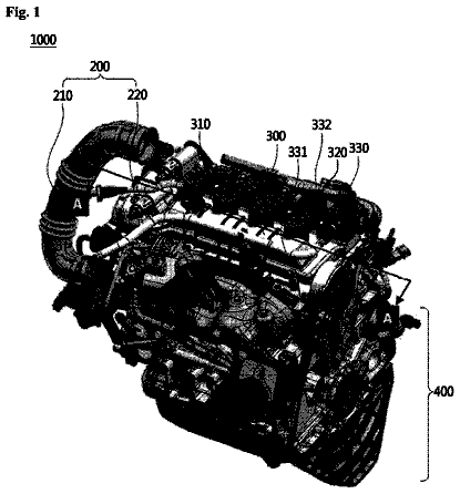
Hereinafter, a first embodiment, which is an embodiment of the present invention, will be described based on drawings ( FIGS. 1 to 12 ). FIG. 1 is a left side view of a diesel engine 1 in which an exhaust manifold 6 is installed, and FIG. 2 is a right side view of the diesel engine 1 in which an intake manifold 3 is installed, and FIG. 3 is a front view of the diesel engine 1 in which a cooling fan 24 is installed. It is noted that the installation side of the exhaust manifold 6 is referred to as the left lateral surface of the diesel engine 1 , and the installation side of the intake manifold 3 is referred to as the right lateral surface of the diesel engine 1 , and the installation side of the cooling fan 24 is referred to as the front surface of the diesel engine 1 . The entire structure of the diesel engine 1 will be described referring to FIGS. 1 to 8 .
As illustrated in FIGS. 1 to 7 , the intake manifold 3 is arranged on one side surface of a cylinder head 2 of the diesel engine 1 . The cylinder head 2 is mounted on a cylinder block 5 in which an engine output shaft 4 (crankshaft) and pistons (not illustrated) are incorporated. The exhaust manifold 6 is arranged on the other side surface of the cylinder head 2 . The front end and the rear end of the engine output shaft 4 protrude from the front surface and the rear surface of the cylinder block 5 .
As illustrated in FIGS. 1 to 7 , a flywheel housing 8 is adhered to the rear surface of the cylinder block 5 . A flywheel 9 is provided in the flywheel housing 8 . The flywheel 9 is pivotably supported on the rear end side of the engine output shaft 4 . It is configured such that the motive power of the diesel engine 1 is taken out via the flywheel 9 . Furthermore, an oil pan 11 is arranged on the lower surface of the cylinder block 5 .
As illustrated in FIGS. 2 to 5 and 7 , an exhaust gas recirculation device (EGR) 15 that takes in the exhaust gas for recirculation is arranged on the intake manifold 3 . An air cleaner 16 (see FIG. 13 ) is connected to the intake manifold 3 . It is configured such that outside air that is purified by removing dust by means of the air cleaner 16 is delivered to the intake manifold 3 and supplied to each cylinder of the diesel engine 1 .
With the aforementioned constitution, part of the exhaust gas discharged from the diesel engine 1 to the exhaust manifold 6 is recirculated from the intake manifold 3 into each cylinder of the diesel engine 1 via the exhaust gas recirculation device 15 , thereby reducing the combustion temperature of the diesel engine 1 , reducing the emissions of nitrogen oxides (NOx) from the diesel engine 1 , and improving the fuel consumption of the diesel engine 1 .
It is noted that a coolant pump 21 for circulating a coolant to the cylinder block 5 and a radiator 19 (see FIG. 13 ) is provided. The coolant pump 21 is arranged on the installation side of the cooling fan 24 of the diesel engine 1 . The coolant pump 21 and the cooling fan 24 are coupled with the engine output shaft 4 via a V belt 22 and the like, thereby driving the coolant pump 21 and the cooling fan 24 . It is configured such that the coolant is delivered from the coolant pump 21 into the cylinder block 5 via an EGR cooler 18 of the exhaust gas recirculation device 15 , while the diesel engine 1 is cooled by the wind of the cooling fan 24 .
As illustrated in FIGS. 1 to 8 , the diesel engine 1 includes a first case 28 as a diesel particulate filter (DPF) that removes particulate matter in the exhaust gas of the diesel engine 1 and a second case 29 as a urea selective catalyst reduction (SCR) system that removes the nitrogen oxides in the exhaust gas of the diesel engine 1 , as an exhaust gas purification device 27 for purifying the exhaust gas discharged from each cylinder of the diesel engine 1 . As illustrated in FIGS. 1 and 2 , an oxidation catalyst 30 and a soot filter 31 are internally provided in the first case 28 as a DPF case. An SCR catalyst 32 and an oxidation catalyst 33 for urea selective catalyst reduction are internally provided in the second case 29 as an SCR case.
The exhaust gas discharged from each cylinder of the diesel engine 1 to the exhaust manifold 6 is released to the outside via the exhaust gas purification device 27 and the like. It is configured such that carbon monoxide (CO), hydrocarbon (HC), particulate matter (PM), and nitrogen oxides (NOx) in the exhaust gas of the diesel engine 1 are reduced by means of the exhaust gas purification device 27 .
The first case 28 and the second case 29 are constituted in a lateral, oblong cylindrical shape elongated in the orthogonal direction intersecting with the output shaft (crankshaft) 4 of the diesel engine 1 when viewed from a plane (see FIGS. 3 to 5 ). A DPF inlet pipe 34 that takes in the exhaust gas and a DPF outlet pipe 35 that discharges the exhaust gas are provided on the cylindrical bilateral sides (one end side and the other end side of the transfer direction of the exhaust gas) of the first case 28 . Similarly, an SCR inlet pipe 36 that takes in the exhaust gas and an SCR outlet pipe 37 that discharges the exhaust gas are provided on the bilateral sides (one end side and the other end side of the transfer direction of the exhaust gas) of the second case 29 .
Also, a supercharger 38 that forcibly feeds air into the diesel engine 1 , and an exhaust gas outlet pipe 7 fastened with bolts to the exhaust manifold 6 are arranged at the exhaust gas outlet of the exhaust manifold 6 . It is configured such that the DPF inlet pipe 34 communicates with the exhaust manifold 6 via the supercharger 38 and the exhaust gas outlet pipe 7 , and the exhaust gas of the diesel engine 1 is introduced into the first case 28 , while the SCR inlet pipe 36 is connected to the DPF outlet pipe 35 via a urea mixing pipe 39 , and the exhaust gas of the first case 28 is introduced into the second case 29 . In addition, the DPF outlet pipe 35 and the urea mixing pipe 39 are detachably connected by fastening with bolts on a DPF outlet-side flange body 41 . It is noted that the SCR inlet pipe 36 and the urea mixing pipe 39 are detachably connected on an SCR inlet-side flange body 40 .
As illustrated in FIG. 2 , a fuel pump 42 and a common rail 43 that are connected to a fuel tank 45 illustrated in FIG. 13 ( FIG. 14 ) are provided in respective injectors (not illustrated) corresponding to the multi cylinders of the diesel engine 1 . The common rail 43 and a fuel filter 44 are arranged on the installation side of the intake manifold 3 of the cylinder head 2 , and the fuel pump 42 is arranged in the cylinder block 5 below the intake manifold 3 . It is noted that each injector includes a fuel injection valve (not illustrated) of an electromagnetic opening/closing control type.
The fuel in the fuel tank 45 is drawn in by the fuel pump 42 via the fuel filter 44 , while the common rail 43 is connected to the discharge side of the fuel pump 42 , and the cylindrical common rail 43 is connected to each injector of the diesel engine 1 . It is noted that surplus fuel, out of the fuel that is pressure-fed from the fuel pump 42 to the common rail 43 , is returned to the fuel tank 45 , and the high-pressure fuel is temporarily retained in the common rail 43 , and the high-pressure fuel in the common rail 43 is supplied into the interior of each cylinder (cylinder) of the diesel engine 1 .
With the aforementioned constitution, the fuel in the fuel tank 45 is pressured-fed to the common rail 43 by means of the fuel pump 42 , and the high-pressure fuel is stored in the common rail 43 , and the fuel injection valves of the injectors are respectively controlled in an openable/closable manner, thereby injecting the high-pressure fuel in the common rail 43 into the injectors of the diesel engine 1 . That is, the fuel injection valve of each injector is electronically controlled, so that the injection pressure, injection time, and injection period (injection amount) of the fuel can be controlled with high accuracy. Accordingly, the nitride oxides (NOx) discharged from the diesel engine 1 can be reduced.
Next, a tractor 51 on which the diesel engine 1 is mounted will be described referring to FIGS. 13 and 14 . The tractor 51 as a work vehicle illustrated in FIGS. 13 and 14 is configured to be equipped with a tilling machine not illustrated and perform tillage so as to till farm fields. FIG. 13 is a side view of a tractor for farm work, and FIG. 14 is a plan view of the tractor. It is noted that, in the description below, a left side with respect to the advance direction of the tractor is merely referred to as “left side”, and a right side with respect to the advance direction of the tractor is merely referred to as “right side”.
As illustrated in FIGS. 13 and 14 , the tractor 51 for farm work as a work vehicle is configured such that a travelling vehicle body 52 is supported by a pair of right and left front wheels 53 and a pair of right and left rear wheels 54 , and the diesel engine 1 is mounted on the front portion of the travelling vehicle body 52 , and the front wheels 53 and the rear wheels 54 are driven by the diesel engine 1 , which allows the tractor 51 to travel forward and backward. The upper surface side and the right and left lateral surface sides of the diesel engine 1 are covered by an openable/closable hood 56 .
Also, a cabin 57 that an operator rides on is installed in the rear of the hood 56 on the upper surface of the travelling vehicle body 52 . A maneuvering seat 58 that the operator takes, and maneuvering instruments such as a maneuvering handle 59 as a steering means are provided in the interior of the cabin 57 . Also, a pair of right and left steps 60 that the operator ascends or descends are provided on the right and left external lateral sections of the cabin 57 , and the fuel tank 45 for supplying the fuel to the diesel engine 1 is provided on the inner side of the steps 60 and on the lower side with respect to the bottom portion of the cabin 57 .
Also, the travelling vehicle body 52 includes a mission case 61 for shifting the output from the diesel engine 1 and transmitting the output to the rear wheels 54 (front wheels 53 ). The tilling machine not illustrated or the like is coupled with the rear portion of the mission case 61 in such a manner as to be capable of being hoisted and lowered via a lower link 62 , a top link 63 , a lift arm 64 , and the like. Furthermore, a PTO shaft 65 for driving the tilling machine and the like is provided on the rear lateral surface of the mission case 61 . It is noted that the travelling vehicle body 52 of the tractor 51 is constituted by the diesel engine 1 , the mission case 61 , and a clutch case 66 that couples the diesel engine 1 with the mission case 61 .
Furthermore, the mounting structure of the first case 28 and the second case 29 will be described referring to FIGS. 1 to 12 and 15 to 17 . As illustrated in FIGS. 9 to 12 and 15 to 17 , a front portion supporting leg body 82 that fastens a lower end side with bolts 81 to a right side corner section on the front surface of the cylinder head 2 , a lateral portion supporting leg body 84 that fastens a lower end side with bolts 83 to a front side corner section on the left side surface of the cylinder head 2 , and a rear portion supporting leg body 86 that fastens a lower end side with bolts 85 to a rear surface of the cylinder head 2 are included, and each of the supporting leg bodies 82 , 84 , and 86 is vertically installed in the cylinder head 2 . A rectangular supporting stand 87 formed by sheet metal working is included, and the lateral surface and the upper surface side of the supporting stand 87 are fastened with bolts 88 to the upper end side of the supporting leg bodies 82 , 84 , and 86 . Also, a tabular positioning body 89 is welded and fixed on the upper surface of the supporting stand 87 installed opposite to the exhaust gas outlet pipe 7 , and part of the tabular lower surface of the positioning body 89 is brought in surface contact with part of a flat exhaust gas outlet surface 7 a of the exhaust gas outlet pipe 7 opened upwardly, and the positioning body 89 is fastened with bolts 90 to the exhaust gas outlet pipe 7 . It is configured that the surface contact of the positioning body 89 with the exhaust gas outlet pipe 7 allows the upper surface of the supporting stand 87 to be approximately horizontal to the diesel engine 1 .
As illustrated in FIGS. 11 and 12, and 15 to 17 , a pair of left case fixing body 95 and right case fixing body 96 , and four fastening bands 97 are included as a clamping body for arranging the first case 28 and the second case 29 in parallel. The first case 28 is adhered with the right and left fastening bands 97 to rear side placement portions of the left case fixing body 95 and the right case fixing body 96 , and the second case 29 is adhered with the right and left fastening bands 97 to front side placement portions of the left case fixing body 95 and the right case fixing body 96 . Accordingly, the first case 28 and the second case 29 , each of which is formed in an oblong cylindrical shape elongated in the right-and-left direction, are arranged in parallel to the upper surface side of the diesel engine 1 , so that the first case 28 is positioned on the rear side of the upper surface of the diesel engine 1 , and the second case 29 is positioned on the front side of the upper surface of the diesel engine 1 .
As illustrated in FIGS. 9 to 12, and 17 , as an exhaust gas purification unit, the exhaust gas purification device 27 is configured such that a front and back supporting frame bodies 98 are fastened with bolts 99 to the front-and-back end portions of the left case fixing body 95 and the right case fixing body 96 in such a manner that a mounting position (supporting posture) can be adjusted, and the left case fixing body 95 and the right case fixing body 96 and the front and back supporting frame bodies 98 are coupled in a rectangular frame shape, and the first case 28 and the second case 29 are adhered to the left case fixing body 95 , the right case fixing body 96 , and the front and back supporting frame bodies 98 via the right and left fastening bands 97 . It is noted that the internal diameter size of the bolt through-hole of the front and back supporting frame bodies 98 is formed larger, compared with the external diameter size of the bolts 99 , and the bolts 99 are inserted into the bolt through-holes of the front and back supporting frame bodies 98 in a freely fittable manner, and it is configured that when the case fixing bodies 95 and 96 are adhered to the front and back supporting frame bodies 98 , while the coupling posture of the front and back supporting frame bodies 98 with respect to the case fixing bodies 95 and 96 is supported in a predetermined posture, the case fixing bodies 95 and 96 are threadedly engaged with the bolts 99 , and the supporting frame bodies 98 are fastened with the bolts 99 to the case fixing bodies 95 and 96 .
Also, right and left hanging members 91 are fastened with bolts 92 to the front end side of the left case fixing body 95 and the rear end side of the right case fixing body 96 , and the right and left hanging members 91 are arranged at diagonal positions of a rectangular frame of the case fixing bodies 95 and 96 and the front and back supporting frame bodies 98 . In contrast, front and rear temporal fixing bolt bodies 93 are vertically installed on the upper surface of the supporting stand 87 disposed approximately horizontally, and the front and rear temporal fixing bolt bodies 93 are arranged at diagonal arrangements of the right and left hanging members 91 and at diagonal positions on the opposite side. That is, the right and left hanging members 91 and the front and rear temporal fixing bolt bodies 93 are allocated and arranged at vertical angle portions of the rectangular frame of the case fixing bodies 95 and 96 and the front and back supporting frame bodies 98 .
Next, the assembly procedure of assembling the exhaust gas purification device 27 (the exhaust purification unit) in the diesel engine 1 will be described. As illustrated in FIGS. 9 to 12 , first, in assembling the exhaust gas purification device (the exhaust purification unit) 27 , a pair of supporting frame bodies 98 made of sheet metal, whose end surface is formed in an L shape, are fastened with the bolts 99 to both end portions of the left case fixing body (clamping body) 95 and the right case fixing body (clamping body) 96 . When the bolts 99 are tightened, looseness between the bolt hole of each supporting frame body 98 and the bolt 99 is utilized in such a manner that the height of the upper surface of the left case fixing body 95 is flush with the height of the upper surface of the right case fixing body 96 , and the bolts 99 are tightened while the coupling positions of the case fixing bodies 95 and 96 and the supporting frame bodies 98 are adjusted, and the case fixing bodies 95 and 96 and the supporting frame bodies 98 are coupled in a rectangular frame shape.
The description continues in the full USPTO document.
 Lapsed, fee not paid5 drawings