 Lapsed, fee not paid4 drawings
Hardware & Electronics · US 9,992,602 B1
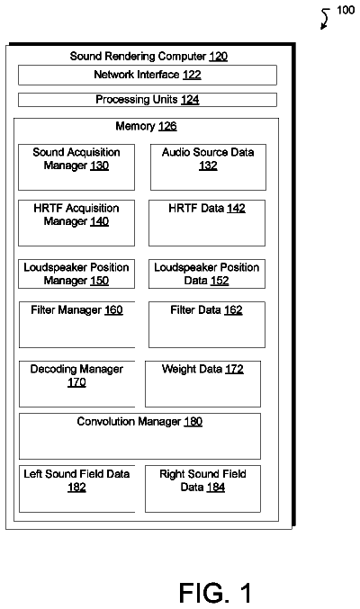
Decoupled binaural rendering
Techniques of performing binaural rendering involve generating separate locations of virtual sources on the sphere for each ear of a listener.
US 9,992,654 B2 · Assignee: AT&T Intellectual Property I, L.P. · Inventors: Kodaypak; Rajendra Prasad et al.
Sheet 1 of 7 from the published document. All sheets in the USPTO PDF
Concepts and technologies disclosed herein are directed to policy driven emergency traffic handling for machine-to-machine (“M2M”) device communication. According to one aspect of the concepts and technologies disclosed herein, an M2M application server can receive a plurality of emergency messages from a mobility management entity (“MME”) over a control plane interface. The plurality emergency message can be generated by a plurality of M2M devices in response to an emergency event. The M2M application server can filter, based upon a policy, the plurality of emergency messages to remove duplicate messages of the plurality of emergency messages in order to create a clean group of emergency messages. The M2M application server can forward the clean group of emergency messages to at least one public safety answering point (“PSAP”).
The Internet of Things (“IoT”) is anticipated to be the next major revolution in the high-speed mobile communications and connectivity industry. A variety of IoT services are likely to be a key growth engine for next generation cellular systems. According to recent studies, approximately 25% of the 20+ billion connected devices that will be deployed globally will fall under the low power cellular ecosystems.
1 of 7 drawing sheets so far from the published document, cropped to the drawing. Every sheet is in the USPTO PDF.
What the patent claimed, word for word. All of it is now free to use.
The Internet of Things (“IoT”) is anticipated to be the next major revolution in the high-speed mobile communications and connectivity industry. A variety of IoT services are likely to be a key growth engine for next generation cellular systems. According to recent studies, approximately 25% of the 20+ billion connected devices that will be deployed globally will fall under the low power cellular ecosystems.
Concepts and technologies disclosed herein are directed to policy driven emergency traffic handling for M2M device communication. According to one aspect of the concepts and technologies disclosed herein, an M2M application server can receive, from a mobility management entity (“MME”) over a control plane interface, a plurality of emergency messages originating from a plurality of M2M devices. The control plane interface can include an MME to M2M application service control plane interface dedicated to control plane message interactions between the MME and the M2M application server.
The plurality of emergency messages are generated by the plurality of M2M devices in response to an emergency event. The M2M application server can filter, based upon a policy, the plurality of emergency messages to remove duplicate messages of the plurality of emergency messages in order to create a clean group of emergency messages. The M2M application server also can forward the clean group of emergency messages to at least one public safety answering point (“PSAP”). In some embodiments, the M2M application server can prioritize at least a portion of the plurality of emergency messages prior to forwarding to the PSAP(s).
The emergency event can be any bona fide emergency or any situation an individual or entity perceives to be an emergency (as is typical of 9-1-1 service). By way of example, and not limitation, the emergency event can be any serious situation where a law enforcement officer, fire fighter, or emergency medical help is needed right away and a call or other communication with the National Emergency Number Association (“NENA”; also known as The 9-1-1 Association) is warranted. The emergency event can be a real-world disaster and/or crisis such as, for example, a hurricane, tsunami, earthquake, tornado, other natural disaster, disease epidemic, and the like.
Each of the plurality of emergency messages can include data. The data can include a type of the emergency event, a priority of the emergency message, an identity of a corresponding one of the plurality of machine-to-machine devices, a location of the corresponding one of the plurality of machine-to-machine devices, a device category, and a device type of the corresponding one of the plurality of machine-to-machine devices. The M2M application server can analyze the plurality of emergency messages to extract the data. The M2M application server can create a mapping table based upon the data. The M2M application server can forward emergency messages to the PSAP(s) based upon the mapping table.
It should be appreciated that the above-described subject matter may be implemented as a computer-controlled apparatus, a computer process, a computing system, or as an article of manufacture such as a computer-readable storage medium. These and various other features will be apparent from a reading of the following Detailed Description and a review of the associated drawings.
This Summary is provided to introduce a selection of concepts in a simplified form that are further described below in the Detailed Description. This Summary is not intended to identify key features or essential features of the claimed subject matter, nor is it intended that this Summary be used to limit the scope of the claimed subject matter. Furthermore, the claimed subject matter is not limited to implementations that solve any or all disadvantages noted in any part of this disclosure.
FIG. 1 is a block diagram illustrating aspects of an operating environment in which the concepts and technologies disclosed herein can be implemented.
FIG. 2 is a block diagram illustrating additional aspects of an MME-M2M application server control plane interface, according to an illustrative embodiment.
FIG. 3 is a flow diagram illustrating a method for policy driven emergency traffic handling for M2M device communication, according to an illustrative embodiment.
FIG. 4 is a block diagram illustrating an example mobile device capable of implementing aspects of the embodiments disclosed herein.
FIG. 5 is a block diagram illustrating an example computer system capable of implementing aspects of the embodiments presented herein.
FIG. 6 is a block diagram illustrating an example network functions virtualization platform (“NFVP”) capable of implementing aspects of the embodiments presented herein.
FIG. 7 is a block diagram illustrating an example network capable of implementing aspects of the embodiments presented herein.
The concepts and technologies disclosed herein provide an integrated dynamic policy driven mechanism within an M2M application server for handling M2M device-generated control plane signaling that can take into account, among other things, the device category, nature of emergency alert, content type during such alert, and location to steer associated traffic to the local emergency/public safety service providers. Such an intelligent mechanism in the M2M application server enables fair treatment to be given to a broader class of M2M devices requesting emergency IoT services.
In long-term evolution (“LTE”) based cellular systems, the MME acts as the nucleus for routing control plane signaling traffic to and from its peer nodes to provide a variety of mobility services. As LTE evolved packet core (“EPC”) networks evolve to support a variety of M2M devices in getting connectivity to the network, the resultant increase in signaling traffic demands intelligent and flexible control plane routing designs to be able to protect the incumbent services as well to deliver next generation IoT services.
In a conventional LTE network, the MME performs critical mobility and session management functions to be able to successfully complete the signaling procedures interworking with its peer network elements. When a large volume of LTE-capable M2M devices with mixed category types connect to the radio access network (“RAN”) elements and the serving MME, these devices could be distributed across multiple tracking areas (“TAs”) that are configured in the MME. During emergency scenarios, when several such M2M devices across these TAs need to attach to the LTE network to send and receive critical information, the serving MME(s) could be overloaded if adequate M2M device specific control plane procedural prioritization and throttling mechanisms are not in place.
When a large volume of M2M devices that belong to a specific service provider need to report their emergency alerts in conjunction with other types of M2M devices, smartphones, and other devices involved in active data exchange, the MME should have the capability to distinguish between various types of machines/devices and traditional mobile users based upon a set of systemic attributes and dynamic policies. The MME can then relay the emergency messages from all such devices towards the M2M application server via control plane data transfer.
The lack of IoT service specific dynamic policy triggers in the M2M application server based upon M2M device category, priority, mobility management state identified via device specific context in the MME visited location register (“VLR”), emergency triggers and location attributes (e.g., cell global identifier and tracking area identifier) could impact the M2M application server's internal message handling/routing capability towards the local public safety authorities (e.g., PSAPs). If the PSAPs are not equipped with adequate message handling capabilities to handle the signaling volumes generated by the MME application server, the PSAPs could, in turn, impact the emergency message delivery process resulting in reduced public safety network functionality and poor customer satisfaction.
In an effort to address the aforementioned issues, the concepts and technologies disclosed herein provide a dynamic IoT service controller that is integrated within an M2M application server so as to evaluate the upstream emergency control plane signaling from several classes of M2M devices, to isolate them for specific emergency types, to analyze and subsequently group them based upon target service identifiers, and to adopt backoff mechanisms in completing their transactions towards the public safety authorities in an efficient manner.
While the subject matter described herein may be presented, at times, in the general context of program modules that execute in conjunction with the execution of an operating system and application programs on a computer system, those skilled in the art will recognize that other implementations may be performed in combination with other types of program modules. Generally, program modules include routines, programs, components, data structures, computer-executable instructions, and/or other types of structures that perform particular tasks or implement particular abstract data types. Moreover, those skilled in the art will appreciate that the subject matter described herein may be practiced with other computer systems, including hand-held devices, mobile devices, wireless devices, multiprocessor systems, distributed computing systems, microprocessor-based or programmable consumer electronics, minicomputers, mainframe computers, routers, switches, other computing devices described herein, and the like.
In the following detailed description, references are made to the accompanying drawings that form a part hereof, and in which are shown by way of illustration specific embodiments or examples. Referring now to the drawings, in which like numerals represent like elements throughout the several figures, aspects of concepts and technologies for policy driven emergency traffic handling for M2M device communication will be described.
Referring now to FIG. 1 , an illustrative operating environment 100 in which the various concepts and technologies disclosed herein can be implemented will be described. The illustrated operating environment 100 includes a plurality of user equipment devices (“UEs”) 102 A- 102 N (referred to herein collectively as UEs 102 , or generally in the singular form as UE 102 ) operating in communication with a radio access network (“RAN”) 104 . The UEs 102 can communicate with the RAN 104 by way of one or more eNodeBs (“eNBs”) 106 . The operating environment 100 also includes a plurality of M2M devices 108 A- 108 N (referred to herein collectively as M2M devices 108 , or generally in the singular form as M2M device 108 ) also operating in communication with the RAN 104 by way of one or more eNBs 106 and/or a home eNB 110 (e.g., femtocell or small cell). For implementations in which an M2M device 108 connects to the home eNB 110 for access to the RAN 104 , the home eNB 110 can route to the RAN 104 via an M2M gateway 112 . The M2M GW 112 provides control capability to manage one or more home eNBs, such as the illustrated home eNB 110 . The M2M GW 112 , in some embodiments, is configured in accordance with 3GPP Technical Release 23.830 architecture. The M2M GW 112 can be configured in accordance with future 3GPP-defined architectures or can be configured in accordance with a proprietary architecture. Although the M2M GW 112 is shown as supporting only the home eNB 110 , it is contemplated that the M2M GW 112 can support multiple home eNBs configured the same as or similar to the home eNB 110 . Likewise, although only a single eNB 106 is shown, the RAN 104 can support multiple eNBs configured the same as or similar to the eNB 106 .
Each of the UEs 102 can be a cellular phone, a feature phone, a smartphone, a mobile computing device, a tablet computing device, a portable television, a portable video game console, or the like capable of communicating with the RAN 104 . The RAN 104 can include one or more service areas (which may also be referred to herein as “cells”) having the same or different cell sizes, which may be represented by different cell-types. As used herein, a “cell” refers to a geographical area that is served by one or more base stations operating within an access network. The cells within the RAN 104 can include the same or different cell sizes, which may be represented by different cell-types. A cell-type can be associated with certain dimensional characteristics that define the effective radio range of a cell. Cell-types can include, but are not limited to, a macro cell-type, a metro cell-type, a femto cell-type, a pico cell-type, a micro cell-type, wireless local area network (“WLAN”) cell-type, a MSMC cell-type, and a white space network cell-type. For ease of explanation, a “small cell” cell-type is utilized herein to collectively refer to a group of cell-types that includes femto cell-type (e.g., home eNB 110 ), pico cell-type, and micro cell-type, in general contrast to a macro cell-type, which offers a larger coverage area. Other cell-types, including proprietary cell-types and temporary cell-types are also contemplated. Although in the illustrated example, the UEs 102 are shown as being in communication with one RAN (i.e., the RAN 104 ), the UEs 102 may be in communication with any number of access networks, including networks that incorporate collocated WWAN WI-FI and cellular technologies, and as such, the UEs 102 can be dual-mode devices.
The M2M devices 108 , in some embodiments, form, at least in part, an IoT network 114 . The M2M devices 108 can be deployed across various industry segments and embedded in a variety of locations, such as basements in multi-dwelling units, underground tunnels, manholes, subway systems, and/or the like, where there could be emergency situations that need to be handled to protect safety of humans, machines, and their interactions.
IoT is a concept of making physical objects, collectively “things,” also referred to herein as the M2M devices 108 , network addressable to facilitate interconnectivity for the exchange of data. The illustrated IoT network 114 can include any number of “things,” including the M2M devices 108 , for example. The M2M devices 108 can be or can include any “thing” that can collect data and that is configured to be network addressable so as to connect to and communicate with one or more networks, such as the RAN 104 , over which to communicate the data to other connected devices, including, for example, computers, smartphones, tablets, vehicles, other M2M devices, combinations thereof, and the like. The M2M devices 108 can be deployed for consumer use and/or business use, and can find application in many industry-specific use cases. For example, the M2M devices 108 may find at least partial application in the following industries: automotive, energy, healthcare, industrial, retail, and smart buildings/homes. Those skilled in the art will appreciate the applicability of M2M-solutions in other industries as well as consumer and business use cases. For this reason, the applications of the M2M devices 108 described herein are used merely to illustrate some examples and therefore should not be construed as being limiting in any way. Although in the illustrated example the M2M devices 108 are shown as being in communication with one RAN (i.e., the RAN 104 ), the M2M devices 108 may be in communication with any number of access networks, including networks that incorporate collocated WWAN WI-FI and cellular technologies, and as such, one or more of the M2M devices 108 can be dual-mode devices.
The UEs 102 and the M2M devices 108 can be associated with an identity (also referred to herein as device identification). The identity can include device identification information such as, for example, International Mobile Subscriber Identity (“IMSI”), a Mobile Station International Subscriber Directory Number (“MSISDN”), an International Mobile Equipment Identity (“IMEI”), or a combination of an IMSI and an IMEI. The device identification information, in some embodiments, can additionally include a device category that specifies a category to which the device belongs. The device identification information can identify the device as being either a device for a standard mobile telecommunications services such a voice and/or data. The device identification information can alternatively identify the device as an IoT or other M2M device. In some embodiments, the M2M devices 108 can be category 1 (“CAT1”), CAT0, CATM based machine-type communication devices, or some combination thereof.
The RAN 104 can operate in accordance with one or more mobile telecommunications standards including, but not limited to, Global System for Mobile communications (“GSM”), Code Division Multiple Access (“CDMA”) ONE, CDMA2000, Universal Mobile Telecommunications System (“UMTS”), LTE, Worldwide Interoperability for Microwave Access (“WiMAX”), other current 3GPP cellular technologies, other future 3GPP cellular technologies, combinations thereof, and/or the like. The RAN 104 can utilize various channel access methods (which may or may not be used by the aforementioned standards), including, but not limited to, Time Division Multiple Access (“TDMA”), Frequency Division Multiple Access (“FDMA”), CDMA, wideband CDMA (“W-CDMA”), Orthogonal Frequency Division Multiplexing (“OFDM”), Single-Carrier FDMA (“SC-FDMA”), Space Division Multiple Access (“SDMA”), and the like to provide a radio/air interface to the UEs 102 . Data communications can be provided in part by the RAN 104 using General Packet Radio Service (“GPRS”), Enhanced Data rates for Global Evolution (“EDGE”), the High-Speed Packet Access (“HSPA”) protocol family including High-Speed Downlink Packet Access (“HSDPA”), Enhanced Uplink (“EUL”) or otherwise termed High-Speed Uplink Packet Access (“HSUPA”), Evolved HSPA (“HSPA+”), LTE, and/or various other current and future wireless data access technologies. Moreover, the RAN 104 may be a GSM RAN (“GRAN”), a GSM EDGE RAN (“GERAN”), a UMTS Terrestrial Radio Access Network (“UTRAN”), an evolved U-TRAN (“E-UTRAN”), any combination thereof, and/or the like. The concepts and technologies disclosed herein will be described in context of the RAN 104 operating in accordance with LTE, although those skilled in the art will appreciate the applicability of the concepts and technologies disclosed herein to other cellular technologies, including, in particular, those captured within future generation 3GPP standards. Moreover, in some embodiments, the RAN 104 is or includes a virtual RAN (“vRAN”).
As used herein, a “base station” refers to a radio receiver and/or transmitter (collectively, transceiver) that is/are configured to provide a radio/air interface over which the UEs 102 and the M2M devices 108 , can connect to a network 116 . Accordingly, a base station is intended to encompass one or more base transceiver stations (“BTSs”), one or more NBs, one or more eNBs (e.g., the eNB 106 ), one or more home eNBs (e.g., the home eNB 110 ), one or more wireless access points (“APs”), one or more multi-standard metro cell (“MSMC”) nodes, and/or other networking nodes or combinations thereof that are capable of providing a radio/air interface regardless of the technologies utilized to do so. A base station can be in communication with one or more antennas (not shown), each of which may be configured in accordance with any antenna design specifications to provide a physical interface for receiving and transmitting radio waves to and from one or more devices, such as the UEs 102 and the M2M devices 108 .
The illustrated network 116 includes two evolved packet core (“EPC”) networks—an EPC for non-M2M devices 118 and an EPC for M2M devices 120 . The EPC for non-M2M devices 118 can provide EPC network functions for non-M2M devices, such as the UEs 102 , in accordance with 3GPP standards specifications. The EPC for M2M devices 120 can provide EPC network functions for M2M devices, such as the M2M devices 108 , in accordance with 3GPP standards specifications and the concepts and technologies disclosed herein.
The EPC for M2M devices 120 can include one or more mobility management entities (“MME”) 122 , one or more M2M application servers (“AS”) 124 , one or more home subscriber servers (“HSS”) 126 , one or more evolved serving mobile location centers (“ESMLC”) 128 , one or more gateway mobile location centers (“GMLC”) 130 , one or more serving gateways (“SGW”) 132 , and one or more packet data network gateways (“PGWs”) 134 . Although not shown in the illustrated embodiment, the EPC for non-M2M devices 118 also can include EPC functions such as, for example, one or more MMEs, one or more HSSs, one or more ESMLCs, one or more GMLCs, one or more SGWs, one or more PGWs, combinations thereof, and the like.
The MME 122 can be configured in accordance with 3GPP standards specifications. The MME 122 , in general, can perform operations to control signaling traffic related to mobility and security for access to the RANs 104 . The MME 122 can perform other operations in accordance with the concepts and technologies disclosed herein, as will be described in detail below.
The HSS 126 can be configured in accordance with 3GPP standards specifications. The HSS 126 is a database that contains user-related information for users of devices. The HSS 126 can provide support functions to the MME 122 for mobility management, call and session setup, user authentication, and access authorization.
The SGW 132 can be configured in accordance with 3GPP standards specifications. The SGW 132 provides a point of interconnect between the radio-side (e.g., the RAN 104 ) and the EPC for M2M devices 120 . The SGW 132 can serve devices by routing incoming and outgoing IP packets between the RANs 104 and the EPC for M2M devices 120 .
The PGW 134 can be configured in accordance with 3GPP standards specifications. In the illustrated embodiment, the PGW 134 interconnects the EPC for M2M devices 120 to one or more other networks 136 , such as, for example, one or more other public land mobile networks (“PLMNs”), one or more packet data networks (“PDNs”) such as, for example, the Internet, one or more circuit-switched networks, combinations thereof, and/or the like. The PGW 134 routes IP packets to and from the other network(s) 136 . The PGW 134 also performs operations such as IP address/prefix allocation, policy control, and charging.
In the illustrated embodiment, the SGW 132 and the PGW 134 are deployed as independent network components within the EPC for M2M devices 120 . In other embodiments, a combined network component—referred to herein as a S/PGW—offering functionality of both the SGW 132 and the PGW 134 can be deployed.
The ESMLC 128 can be configured in accordance with 3GPP standards specifications. The ESMLC 128 can manage the coordination and scheduling of resources to acquire the location of the M2M devices 108 .
The GMLC 130 can be configured in accordance with 3GPP standards specifications. The GMLC 130 interfaces with other entities in the EPC for M2M devices 120 and external systems, such as one or more PSAPs 138 operating in communication with the other network(s) 136 to provide location based services, including providing the location of devices such as the M2M devices 108 .
The core network components of the EPC for M2M devices 120 and the EPC for non-M2M devices 118 can be implemented as physical network functions (“PNFs”) having hardware and software components. The core network components can additionally or alternatively be provided, at least in part, by virtual network functions (“VNFs”). For example, the core network components can be realized as VNFs that utilize a unified commercial-off-the-shelf (“COTS”) hardware and flexible resources shared model with the application software for the respective core network components running on one or more virtual machines (“VMs”). An example network virtualization platform (“NVP”) architecture that might be used to implement various core network components embodied as VNFs is described herein below with reference to FIG. 6 . Moreover, the core network components can be embodied as VNFs in one or more VNF pools, each of which can include a plurality of VNFs providing a particular core network function. For example, the MME 122 , the M2M AS 124 , the HSS 126 , the ESMLC 128 , the GMLC 130 , the SGW 132 , the PGW 134 , or any combination thereof can be implemented as standalone VNFs or as a VNF operating in a VNF pool.
The PSAPs 138 are entities responsible for answering emergency messages and calls to an emergency telephone number, and for dispatching emergency services such as police, firefighters, and ambulance services. PSAPs can identify caller locations for landline calls and mobile calls. For landline calls, the PSAP utilizes the name, address, and telephone number associated with the landline telephone used to make the call. For mobile calls, the PSAP utilizes the address of the base station serving the mobile device that originated the call, telephone number, and estimated location of the mobile device.
In accordance with the concepts and technologies disclosed herein, the MME 122 and the M2M AS 124 are in communication via an MME-M2M AS control plane (“CP”) interface 140 . The MME-M2M AS CP interface 140 provides a direct interface on the control plane between the MME 122 and the M2M AS 124 . The MME 122 can utilize the MME-M2M AS CP interface 140 to forward emergency messages (best shown in FIG. 2 ) received from the M2M devices 108 to the M2M AS 124 , which can analyze, filter, prioritize, and map the emergency messages in accordance with one or more policies prior to forwarding the emergency messages to one or more of the PSAPs 138 .
In LTE-based cellular systems, such as illustrated in the operating environment 100 , the MME 122 acts as the nucleus for routing control plane signaling traffic to and from its peer nodes to provide a variety of mobility services. As LTE-EPC core networks evolve to support a variety of M2M devices—for example, the EPC for M2M devices 120 that supports the M2M devices 108 —in getting connectivity to the network 116 , the resultant signaling traffic demands intelligent and flexible control plane routing designs to be able to protect the incumbent services as well as in delivering next generation IoT services.
In a conventional LTE network, such as provided, in part, by the EPC for non-M2M devices 118 , an MME performs critical mobility and session management functions to be able to successfully complete the signaling procedures interworking with its peer network elements. When a large volume of LTE-capable M2M devices, such as the M2M devices 108 , with mixed category types connect to the RAN 104 and their serving MME (e.g., the MME 122 ), the M2M devices 108 could be distributed across multiple tracking areas (“TAs”) that are configured in the MME 122 . During emergency scenarios, when several of the M2M devices 108 across the multiple TAs need to attach to the network 116 to send/receive critical information, such as emergency information, the MME 122 could enter an overload condition if there are not adequate M2M device specific control plane procedural prioritization and throttling mechanisms in place.
When a large volume of the M2M devices 108 that belong to a specific service provider's network (e.g., the network 116 ) need to report their emergency alert messages in conjunction with other types of devices, such as the UEs 102 , involved in active data exchange, the MME 122 should have the capability to distinguish between various types of machines/devices and traditional mobile users based on a set of systemic attributes and dynamic policies. The MME 122 can relay the emergency alert messages from all such devices towards the M2M AS 124 via control plane data transfer over the MME-M2M AS CP interface 140 .
The lack of dynamic policy triggers and throttling controls for handling the M2M devices 108 , integrated into the key control plane network elements, such as the MME 122 , and their direct interworking with the M2M AS 124 , might result in inefficient emergency communications amidst the broader category of M2M devices supported by the serving mobility network and associated IT application systems. Moreover, when a multitude of M2M devices 108 flood the MME 122 with emergency alerts to communicate towards their respective application providers, this could result in an emergency M2M traffic storm at the MME 122 , which, in turn, has a direct impact on the application server. Emergency alerts, when relayed from the M2M AS 124 towards their respective PSAPs 138 , without proper filtering mechanisms in place, could degrade the mobility network functionality and impact IoT services delivery.
In an effort to address the aforementioned issues, the concepts and technologies disclosed herein provide functionality that is integrated within the M2M AS 124 so as to evaluate the upstream emergency control plane signaling from several classes of M2M devices, to isolate them for specific emergency types, to analyze and subsequently group them based upon target service identifiers, and to adopt backoff mechanisms in completing their transactions towards the PSAPs 138 in an efficient manner.
A broader category of LTE based M2M devices could utilize a combination of control plane and user plane data transfer methods to communicate with the mobility core network, such as the illustrated EPC for M2M devices 120 . Typically control plane procedures are more efficient for short data transmission as they can deliver such messages via signaling without need for more complex bearer establishment procedures. User plane methods could be selected by the network elements such as the MME 122 and the M2M AS 124 on-demand when there is a large data transfer depending on the content type, application requirements, and transport layer QoS.
During emergency situations in a given geographical area, a large volume of the M2M devices 108 could recover from a network failure and try to attach to the network 116 . It is also possible that the M2M devices 108 are forced to report their emergency conditions due to an internal or external fault in their surrounding environment which has no bearing on the network 116 . Under such circumstances, when the M2M devices 108 connect to the network 116 requesting emergency access, the M2M devices 108 could potentially flood the network elements and application systems, such as those shown in the EPC for M2M devices 120 .
As the M2M devices 108 establish radio access and connectivity to the EPC for M2M devices 120 , the MME 122 ensures that the M2M devices 108 are registered and attached to the network 116 . When the M2M devices 108 send emergency messages, the MME 122 accepts these messages at the expense of shedding non-emergency requests and/or ongoing active calls and/or data sessions for other services. While all such emergency requests from all types of M2M devices may not be critical at a given time, the MME 122 could still route them to the M2M AS 124 for further upstream handling.
The M2M AS 124 can receive emergency messages via control plane communication from the MME 122 or MMES 122 in a given regional VNF pool. It is also possible that a regional pool of MMES 122 may communicate with more than one M2M AS 124 depending on the operator specific network scale, capacity, and engineering guidelines. If the M2M AS 124 does not employ any dynamic policy-based filtering of such emergency messages, the M2M AS 124 could flood the regional PSAPs 138 resulting in major network and service delivery impacts.
With the help of M2M AS 124 based intelligent device detection, filtering, and subsequent processing of a true emergency message among a class of emergency types (e.g., type of alarms, intensity, specific event driven short message alerts, and the like) associated with several class/groups of M2M devices 108 , the M2M AS 124 can distinguish and prioritize true emergency messages received from the MME(s) 122 to be able to direct the true emergency messages to the proper one or more of the PSAPs 138 . Emergency types can be defined based upon criticality or source of the emergency. For example, different emergency types can be “natural disaster,” “medical emergency,” “fire emergency,” “public emergency,” and the like. Such a dynamic message filtering and routing mechanism within the M2M AS 124 can prevent flooding of the PSAPs 138 as the PSAP 138 might not be able to handle such large ingress traffic volumes as well as duplicate emergency messages. This could result in impacts to mainstream emergency services that need to be avoided. Egress rate throttling in the M2M AS 124 in addition to the proactive filtering and prioritization can help mitigate such situations. The M2M AS 124 operations can include complex policies and rules to achieve smart throttling and filtering of emergency messages. By cross-analyzing a large set of data and information received during a flood of emergency messages, the M2M AS 124 will have the capability of rationalizing, prioritizing, and identifying duplicate messages or diverse messages signaling the same emergency.
In order for the M2M AS 124 to make such intelligent decisions, the M2M AS 124 can retrieve the entire context or a critical portion of the context of the M2M devices 108 on-demand via control plane message exchange towards each of the serving MMEs. Signaling message exchanges between the MME 122 and the M2M AS 124 could be handled via an IETF standards defined protocol, such as DIAMETER, or any other application mechanism. The critical portion of the context can include, but is not limited to, a user name, device identifier, device category, device priority, device mobility management state, location, some combination thereof, and/or the like.
Given the large volume of devices trying to communicate with the M2M AS 124 , in some embodiments, the M2M AS 124 can retrieve the device context from a centralized database server (not shown) associated with the MME 122 or that is common to an MME pool. Such an architecture could simplify the context retrieval process in a large MME pool configuration. For a small scale deployment such as peer-to-peer configuration and/or the M2M AS 124 connected to few MME nodes, it is possible to resort to the control plane method described above.
Once the M2M AS 124 retrieves the device context, the M2M AS 124 can analyze the device context along with any ongoing signaling message exchanges with the MME 122 , and can then trigger a dynamic policy that can consolidate emergency requests of a certain type from a certain class of M2M devices. For example, the M2M AS 124 can extract the device type, device priority, and the MM/SM state from the device context, and then correlate that with the emergency type being requested. Upon further analysis, the M2M AS 124 can evaluate whether emergency bearer establishment is required based on the content type to be exchanged with a given PSAP provider. Such triggers towards the EPC for M2M devices 120 could be initiated by the M2M AS 124 based upon the content received and processed to ensure mobility network resources (e.g., 122 , 126 , 128 , 130 , 132 , 134 , and/or the like) are effectively utilized to address and resolve the specific emergency needs in a timely manner.
For short message delivery, it could then format such communication towards a regional PSAP and send it as a unique short message rather than sending it as multiple single device specific short messages. This will prevent the PSAP from flooding by being able to receive the request, process it and respond to it promptly. Similarly, the AS could trigger the MME to setup a session establishment process for user plane data transfer if required on demand so that the devices can communicate with the IoT APN to their service providers accordingly.
When the network elements recover from failure during an emergency scenario in a given region and the M2M devices 108 need to attach to the network 116 , the M2M devices 108 can send an attach request to signal to the MME 122 for connectivity to the M2M AS 124 . The MME 122 can determine how to route this request based on its internal evaluation of the attach type and device capabilities.
For direct message exchange to occur between the MME 122 and the M2M AS 124 via control plane method, a new signaling interface—that is, the MME-M2M AS CP interface 140 —is defined. The application protocol described above can operate over this interface to establish a peer-to-peer connectivity model for exchanging messages.
By providing a secure, fast and reliable communication channel between the MME 122 and the M2M AS 124 , network operators can ensure that emergency triggers received by the MME 122 from the M2M devices 108 could promptly be delivered to the M2M AS 124 . If DIAMETER protocol is chosen, then the operator could leverage one or more centralized DIAMETER routing agents to direct this traffic from the MME 122 towards the M2M AS 124 .
The M2M AS 124 also can leverage connectivity with the MME 122 to request additional information from the M2M devices 108 via the user plane in order to better identify the nature of the emergency. In such scenarios, the M2M AS 124 can trigger the MME 122 to setup bearer establishment via a certain IoT/M2M access point name (“APN”) of choice. The MME 122 could then proceed with a session establishment process and setup bearer services to transfer the data over the user plane to the M2M AS 124 .
Since the M2M AS 124 also should be reachable via the user plane, the M2M AS 124 can interact with the PGW 134 via the existing SGi interface through a secure data connection. Alternatively, the M2M AS 124 could have a direct interface towards the PGW 134 for user plane data transfer. A modified Rx interface could be used between the M2M AS 124 and one or more policy and charging rules functions (“PCRFs”) for exchanging dynamic rules created by the M2M AS 124 . The PCRF could then trigger the rules to the PGW 134 for dedicated bearer initiation to extract certain key data on-demand with a desired QoS.
Turning now to FIG. 2 , a block diagram illustrating additional aspects (generally shown at 200 ) of the MME-M2M AS CP interface 140 will be described, according to an illustrative embodiment. FIG. 2 shows the M2M devices 108 , the MME 122 , the M2M AS 124 , the PSAPs 138 , and the MME-M2M AS CP interface 140 introduced above with reference to FIG. 1 .
In the illustrated example, the M2M devices 108 A, 108 B are exposed to an emergency event 202 A; the M2M devices 108 C, 108 D are exposed to an emergency event 202 B; and the M2M devices 108 E, 108 N are exposed to an emergency event 202 N. The emergency events 202 A- 202 N (hereinafter referred to collectively as emergency events 202 , or in the singular as emergency event 202 ) can be any bona fide emergency or any situation an individual or entity perceives to be an emergency (as is typical of 9-1-1 service). By way of example, and not limitation, the emergency events 202 can be any serious situation where a law enforcement officer, fire fighter, or emergency medical help is needed right away and a call or other communication with the National Emergency Number Association (“NENA”; also known as The 9-1-1 Association) is warranted. The emergency events 202 can be a real-world disaster and/or crisis such as, for example, a hurricane, tsunami, earthquake, tornado, other natural disaster, disease epidemic, and the like.
The description continues in the full USPTO document.
About 6,450 words. The USPTO PDF has it with every drawing.
Fees are due 3.5, 7.5 and 11.5 years after grant. This patent expired on June 5, 2026, so the fee marked "not paid" was the one that went unpaid.
Policy Driven Emergency Traffic Handling for Machine-to-Machine Device Communication
Filed Apr 2016 · published Nov 2017Policy driven emergency traffic handling for machine-to-machine device communication
Filed Apr 2016 · granted Jun 2018Earlier publications, parents and continuations. None of them can still be enforced, or this patent would not be listed.
Prior art cited by the examiner or applicant. Useful when you check your own idea for novelty.
Everything on this page comes from the documents linked above.


