Field of the invention
The invention relates to underground mining operations conducted beneath a rock layer.
Background of the invention
Reference to any prior art in the specification is not, and should not be taken as, an acknowledgment or any form of suggestion that this prior art forms part of the common general knowledge in Australia or any other jurisdiction or that this prior art could reasonably be expected to be ascertained, understood and regarded as relevant by a person skilled in the art.
Drilling to detect gold-bearing alluvium beneath the basalt cover has, for over 100 years, been the only means of prospecting for deep leads. These holes, usually diamond drilled, provide little data other than the thickness of basalt cover and alluvium, and the depth of bedrock. The presence of gold was often not able to be determined.
Determining the location and boundaries of deep lead gold deposits and the assessment of their economic potential is difficult, and the results are considerably less definitive than for many other types of mineral deposits.
Generally speaking, for a deep lead, the mineralised target zone is narrow relative to the breadth of the original valley floor, and more so compared with the width of the basalt sheet which later flooded the valley, sometimes obscuring it entirely. It is impossible therefore, to use surface geological evidence to trace the course of the narrow and sinuous river bed which carries the auriferous gravel deposits. The only practical means of exploration has been the drilling of lines of holes across the presumed likely course of the lead. This is effective in outlining the general profile of the original valley floor, and in locating thicker accumulations of wash. However, the cost of a drill pattern of sufficiently close spacing to detect bedrock gutters of only a few tens of meters width has been regarded as prohibitive.
The general experience of using drill-hole results to determine gold concentrations in the wash has proved quite unreliable. To penetrate the basalt cover, small diameter drilling (200 mm and less) has had to be used. Holes of this size provide a sample volume much too small for reliable grade determination in poorly consolidated gravel and sand which contains coarse gold particles. The larger gold grains are often not recovered by the drilling method and frequently, results appear to have understated even the local grades within a deposit. Modern exploration geophysical methods have been applied with mixed success in determining depths of basalt and bedrock in deep lead areas.
The distribution of gold particle size along the trend of the lead is of significance in assessing the likelihood that the lead may have been charged at several points along its course with gold derived from tributary streams, or from bedrock reef outcrops which it may have traversed. Geologically, the introduction of gold at various points along its course is expected to be considerably more favourable for the downstream persistence of economic concentrations, than if the only source was at the head of the lead.
Any mining method which proposes to exploit these deep lead deposits will have to operate through a depth of cover of up to 120 m. Most commonly this consists of fairly competent and free-standing basalt. The immediate hanging wall to the gold bearing wash is often a poorly consolidated and heavily water-bearing section, in the range of up to 100 m thick, of sand and clay which carries little, if any gold. The specially developed underground mining methods of the early miners were able to extract the thin (0.5 to 1.5 m) layer of gold bearing wash without suffering significant dilution from these overlying sand and clay beds. The development of a method which can profitably mine these deeps leads without the requirement for intensive underground labour would constitute a major technological advance.
A number of methods have been proposed for mining from boreholes. The basis of these has generally been the use of water-jets to break up the alluvium and the pumping the resulting slurry to the surface. The problem with these systems is basically one of cost. In an unconsolidated deposit such as a Deep Lead the lower grade roof will feed into the cavern. This means that a large volume of “overburden” will be extracted to extract a small volume of wash. The water jet is likely to have a short range as it is operating in water which will disperse the force. The net result is that a large number of boreholes are required to extract the wash and the economics are unlikely to be favourable. Furthermore, there are environmental pressures which limit the types of methods that can be employed to extract the gold—regardless of how safe a process could be proven to be in many cases they are unacceptable to the local community.
In light of the above, it would be advantageous to have mechanisms for extracting desirable minerals from underground alluvial deposits that are contained beneath a rock layer, such as a basalt layer.
Summary of the invention
There are a number of potential options for extraction of a mineral from mineral containing alluvial deposits. However, many of these options are not practical for environmental, economic, or public perception reasons. Thus in one aspect, the present invention is directed towards an alternative method of extracting mineral containing alluvial deposits using a deep lead suction dredging process. Preferably the mineral contained in the alluvial deposits is gold.
In one aspect of the invention there is provided a method of extracting alluvial deposit from an underground source beneath a rock layer, the method including: drilling a bore hole through the rock layer; extracting some of the alluvial deposit from beneath the rock layer to form an excavated zone; lowering at least two components into the excavated zone, each component having an umbilical; assembling the at least two components into a remote operated vehicle (ROV); using the remote operating vehicle to mine the alluvial deposit and provide the mined alluvial deposit to the surface via at least one of the umbilicals.
Preferably the rock layer is a hard rock layer. For example the rock layer may be a basalt layer or another rock formed from solidified lava, or other rock layer that restricts access to an alluvial material contained beneath it.
Preferably the bore hole has a diameter of around 1.8 m.
Preferably at least three components are lowered into the excavated zone and are assembled into the ROV.
Preferably the mined mineral alluvial deposit is processed at a processing plant on the surface to extract the material of interest, resulting in a mineral depleted alluvial material. More preferably, at least some of the mineral depleted alluvial material is returned and used to backfill the excavated zone.
In another aspect of the invention there is provided a remote operated vehicle (ROV) for use in an underground mining of an alluvial deposit from beneath a rock layer, the remote operated vehicle including: at least a first component having a first umbilical, the first component sized to fit down a borehole; and a second component having a second umbilical, the second component sized to fit down the borehole; wherein the first and second component are configured to be joined together in an excavated region beneath the rock layer to form the remote operated vehicle.
ROVs have been used in underwater environments for recovery of bed materials, such as sea bed materials in the case of an undersea ROV. The following discussion is in relation to undersea ROVs, but is equally applicable to general underwater ROVs. Undersea ROV's are generally not suitable for use in underground environments. Firstly, the excavated region of an underground environment is not necessarily flooded with water, as many of the undersea ROV's are designed for propulsion through water, these ROVs are not adapted for use in an environment that is not flooded. Secondly, an underground environment that is flooded with water will contain a large amount of suspended solids from the mining and excavation process as compared with a undersea environment in which the ROV is mostly operating in seawater that has a very low concentration of suspended solids. The, water in an underground excavated region is likely to be in the form of a particulate laden solution, such as a slurry or an alluvial slurry. The ROV must therefore be capable of operation in an aqueous environment that is laden with particulate material or is a slurry.
Furthermore, undersea ROV's are not generally limited in terms of size. The ROV is either a unitary device or can be assembled on the deck of vessel or platform before being lowered into the ocean. There is no need to assemble the ROV from constituent components undersea. Moreover, the ROV can more easily and simply be assembled above the water prior to being lowered into the water.
In contrast, ROV's that are operated beneath a rock layer in an underground environment may have size limitations placed upon them. In order to access an underground alluvial deposit that is beneath a rock layer, a borehole is drilled through the rock layer. Boreholes are expensive and time consuming to produce. Therefore, the inventor has determined that it can be advantageous to minimise the diameter of the borehole and still be able to mine a deposit under a rock layer with an ROV if one lowers constituent components of an ROV through the borehole and then assembles the ROV underground, for example in an excavated region beneath the rock layer. Together these components are assembled to form an operable ROV that can be used to mine and extract alluvial deposits from underground. As the ROV is lowered in a number of pieces which are sized to fit through the borehole, the size of the ROV once it is assembled underground is larger than the borehole in at least one dimension.
Thus, preferably once at least the first and second components have been assembled together, the ROV has a size that is greater than either the first or the second components. For example, an outer dimension, such as a width or a length, of the ROV is greater than a corresponding outer dimension of the first or second components. More preferably, the volume bounded by the periphery of the ROV is greater than a volume bounded by either of the first or the second components.
In an embodiment, the ROV is operable to extract an alluvial deposit only once the first and second components have been joined together.
Preferably the at least two components are assembled by bolts or snap links.
Preferably the first component includes the drive mechanism, and the second component includes the dredging and/or mining equipment.
In an alternative arrangement at least three components are lowered into the excavated zone and are assembled into the ROV; the first component, the second component, and a third component. In this alternative arrangement, it is preferred that, the first component and the third component are a left hand and right hand drive mechanism of the ROV and the second component includes the dredging and/or mining equipment. Even more preferably, the first component and the third component are assembled on to the second component. In another aspect of the invention there is provided a remote operated vehicle for use in underground mining of an alluvial deposit from beneath a rock layer, the remote operated vehicle sized to fit down a borehole including: an umbilical, a plurality of ground engaging drive mechanisms which preferably include at least two pairs of ground engaging drive mechanisms, wherein the ground engaging drive mechanisms are operable in a first mode (e.g. such as in the same direction) to propel the vehicle, and are operable in a second mode (e.g. such as in opposing directions) to displace the alluvial deposit from an underlying rock layer, suction means to extract the displaced alluvial deposit and provide the displaced alluvial deposit to an above ground reservoir via the umbilical.
The two pairs of ground engaging mechanisms may for example be a front pair of ground engaging mechanisms and a rear pair of ground engaging mechanisms. The front and rear pairs of ground engaging mechanisms are operable in the same direction to propel the vehicle in a desired direction (such as forward or backward). However, the front and rear pairs of ground engaging mechanism are also operable in opposing directions. For example, the front pair of ground engaging mechanisms is operated in one of the forward or the backward direction and the rear pair of ground engaging mechanisms is operated in the other of the forward or the backward direction. The effect of this operation is that the ground engaging mechanisms provide a grinding effect on the surface with which the ground engaging mechanisms are engaged. This liberates or displaces an alluvial deposit from an underlying rock layer, which results in the alluvial deposit being more easily extracted, for example through a dredging or suction process.
It will be understood that, in this example, the front pair of ground engaging mechanisms and the rear pair of ground engaging mechanisms are operable in opposing directions at different rates. This allows the ROV to be operated so that it can move in the forward or reverse directions while also providing a grinding effect on the surface with which the ground engaging mechanisms are engaged. By way of example, the front pair of ground engaging mechanisms may be operated in the forward direction at greater speed or torque than the rear pair of ground engaging mechanisms which are operated in the reverse direction. The effect of this is that the ROV moves in the forward direction even though the rear pair of ground engaging mechanisms are operated in the reverse direction. In this way, the rear pair of ground engaging mechanisms provide a grinding effect to the surface beneath the ROV to liberate or displace alluvial deposit from the underlying rock layer.
It will be understood that reference to the front pair of ground engaging mechanisms and the rear pair of ground engaging mechanisms is illustrative only. The ROV may instead include two side pairs of ground engaging mechanisms, such as a right hand side pair of ground engaging mechanisms, and a left hand side pair of ground engaging mechanism. Each of the right hand side pair and left hand side pair are operable in the right or left hand directions to result in the effect described above.
In respect of the above two aspects directed toward the ROV, it is preferred that the drive mechanism is selected from the group consisting of tracks, wheels, or screw-propulsion for movement over a surface.
In another aspect of the invention there is provided a remote operated vehicle for use in an underground mining of an alluvial deposit from beneath a rock layer, the remote operated vehicle including: a plurality of components sized to fit down a borehole, each component having an umbilical, and wherein each component is configured to be joined together in an excavated region beneath the rock layer to form the remote operated vehicle.
It is preferred that at least one of the plurality of components contains the mining equipment and at least one of the plurality of components includes the drive mechanism. More preferably the ROV includes multiple drive mechanism components that may be the same or different, e.g. each drive mechanism is independently selected from the group consisting of tracks, wheels, or screw-propulsion for movement over a surface. In this way, an ROV may include 2, 3, 4, or more drive units that may be the same or different. One or more of the drive units may be engaged in moving the vehicle, while one or more are engaged in an operation to displace alluvial material e.g. brushing, sweeping, or excavating alluvial material. In respect of the above three aspects directed toward the ROV, it is preferred that the ROV is amphibious and can perform the dredging/mining operation in an underwater environment. More preferably, the ROV includes aqueous propulsion means selected from the group consisting of a propeller, fins, or water-jet.
In respect of the above three aspects directed toward the ROV, it is preferred that the ROV includes a waste pipeline for depositing a mineral depleted alluvial material, or an alluvial deposit with a low mineral concentration in a backfill location underground beneath the rock layer.
In respect of the above three aspects directed toward the ROV, it is preferred the ROV includes a water cannon and/or mechanical cutter for breaking up the mineral alluvial deposit and/or to alter the consistency of the mineral alluvial deposit to create a slurry.
In respect of the above three aspects directed toward the ROV, it is preferred that the ROV includes a fail-safe mode, wherein when communications between an operator and the ROV are no longer possible a safety mechanism is deployed. More preferably, the safety mechanism is an airbag (or flotation bag) type system, which when deployed, lifts the ROV from the floor of the excavated region.
In respect of the above three aspects directed toward the ROV, it is preferred that the ROV includes survey means. Preferably the survey means is selected from the group consisting of sonar, ultrasound, optical camera, or combinations thereof.
In another aspect the present invention provides a method for supporting a rock layer overlying an excavated region. The method includes, forming one or more support structures between a base of the excavated region and a ceiling of the rock layer for supporting the rock layer above the excavated region.
Preferably forming the one or more support structures includes injecting a settable material to form at least one support structure in situ. The method can also include reinjecting material excavated from the cavity into the cavity. In a one preferred embodiment the method includes reinjecting material excavated from the cavity into the cavity, and forming support structures in said reinjected material.
In some cases the method can involve using said settable material as a binder mixed with another material to form one or more composite support structures. The settable material and other material can be mixed prior to injection of them into the cavity. Alternatively the settable material can be injected directly into the other material in situ where a support structure is to be formed.
Reinjection of either or both of settable material or material excavated from the cavity, can be performed from the surface to a site of a support structure to be formed. Alternatively, reinjection of either or both of settable material or material excavated from the cavity, can be performed using a remotely operated vehicle located within the cavity. Both techniques could be used together at the one site.
The method may include providing a mould, form or container to contain the settable material prior to hardening, said mould, form or container being left in place after hardening. For example the mould, form or container is a bag or the like that is filled with settable material.
Support structure can be of any type, such as a support pillar, support block, or structure of an amorphous shape.
In another aspect of the invention, there is provided a method for supporting a rock layer overlying an excavated, the method including: forming one or more support pillars between a base of the excavated region and a ceiling of the rock layer using a remote operated vehicle, the pillar or pillars supporting the rock layer above the excavated region. Preferably, the ROV is an ROV as previously described.
At least a component material from which the pillars are formed may be provided from the surface via an umbilical of the ROV. For example, a settable material such as cement may be supplied from the surface to the ROV where the ROV applies the material at an appropriate location. In certain embodiments, excavated alluvium is used as aggregate combined with the settable material to form composite pillar(s). In a preferred form, where the settable material is cement, a portion of the excavated alluvium can be combined with the cement to form concrete pillars. This may be the case where the excavated alluvium is found to be too low in the material of interest, instead of transporting this alluvium to the surface it can be used to form the support pillars. Alternatively, or additionally, depleted alluvium (which has had the material of interest at least partially removed) may be recycled as a composite constituent and returned via the umbilical to the ROV for use in the support pillar. In certain embodiments the pillars can comprise a containment envelope, e.g. a bag, tube or the like, that acts as a form work to hold the settable material. In one form, this could take the form of plastic bags filled with concrete.
In another aspect of the invention there is provided a pipe for use in underground mining of an alluvial material from beneath a rock layer, the pipe including: a debris trap portion, wherein the debris trap portion has a closed state for transporting the alluvial material and trapping large debris, and an open state for releasing the trapped debris.
In an embodiment the trap portion of the pipe further includes hinges arranged along the longitudinal axis of the pipe, wherein the debris trap portion can be split open along the longitudinal axis to release the trapped debris.
In an alternative embodiment the trap portion further includes hinges arranged in such a manner that the debris trap portion of the pipe opens radially outward to release trapped debris.
In both of the above embodiments it is preferred that the hinges include a tab that has a locked position and an unlocked position, wherein when the tab is in the locked position the debris trap portion is locked in the closed state, and when in the tab is in the unlocked position, the debris trap portion may be moved into the open state. More preferably the tabs can be actuated by fluid flow that is in the reverse direction to the direction of transport of the alluvial material.
Preferably the debris trap portion is selected from the group consisting of a U-bend, S-bend, J-bend, or P-bend. More preferably, the trap portion is a U-bend.
Preferably, the pipe includes a screen on an inlet.
In another aspect of the invention there is provided a suction dredge including: a dredge pump; a suction pipe; a debris trap in fluid communication with the suction pipe, the debris trap including a tortuous flow path; wherein the debris trap is reconfigurable between an operable condition in which it defines a flow path in fluid communication with the suction pipe in through which dredged material may be sucked and being sized to capture oversized objects; and an inoperable condition in which the flow path is opened to release trapped objects.
Preferably the suction dredge includes an ROV as previously defined, the ROV connecting between the dredge pump and the suction pipe.
In another aspect of the invention there is provided a device for in-line monitoring of a mining material from a mining process, the device including: at least two conductive electrodes separated by a non-conductive spacer, the conductive electrodes arranged so as to overlap at least a portion of the non-conductive spacer, the overlap defining a spacing between the two conductive electrodes through which alluvial material can pass, the conductive electrodes configured to detect the presence of a material of interest in the alluvial material as it passes therethrough.
Preferably the conductive electrodes are plate shaped.
In another aspect of the invention there is provided a method for in-line monitoring of the concentration of a material of interest in a mining material obtained from a mining process, the method including: providing at least one device as defined above within a flow path for transporting the mining material, passing at least some of the mining material through the spacing between the two conductive electrodes, and determining the presence of the material of interest in the mining material.
In yet another aspect of the invention there is provided an in-line monitoring device for detecting a material of interest in a mining material, the device including: a plurality of electrodes including at least a first electrode which is a positive or a negative electrode, and second and third electrodes which are opposite in charge from the first electrode, the first electrode being separated from the second and third electrodes by a non-conductive space or spaces through which mining material can pass, the device configured to detect the presence of the material of interest in the mining material as it passes through the space and forms an electrical connection between the first electrode and at least one of the second or third electrodes.
Preferably the first electrode is configured to form with each of the second and third electrodes a different electrical circuit. Thus when a material of interest forms an electrical connection between the first electrode and the second electrode, a first electrical circuit is established, and when a material of interest forms an electrical connection between the first electrode and the third electrode, a second electrical circuit is established. In this way, it is possible to determine the spatial location of the particle on detection by identifying which circuit has been activated. Furthermore, if there is different electrode spacing between the first electrode and the second electrode as compared with the first electrode and the third electrode (as will be discussed in more detail) size information on the material of interest can be obtained.
Furthermore, this arrangement avoids an issue which can arise where particles become lodged between electrodes. Often conductive particles become lodged and are entrapped between a pair of electrodes. In some instances, the particle will remain lodged there until it is manually removed, for example during a cleaning or servicing operation. If the electrodes are arranged in a single circuit, the presence of the entrapped conductive particle could cause the sensor to malfunction, as the sensor would continue to generate a signal identifying the presence of a conductive particle as long as the jammed particle remained lodged between electrodes. Furthermore, as the pairs of electrodes have been arranged on separate electrical circuits, a false positive signal resulting from the jammed particle may be removed or filtered out electronically or via software.
In an embodiment, the electrodes are arranged in a stack, with the first electrode being located at a first distance in the stack from the second electrode and at a second distance in the stack from the third electrode, the first distance being less than the second distance. Preferably the electrode stack there are more than three electrodes in the plurality of electrodes. More preferably, the electrode stack includes more than four electrodes. Even more preferably, the electrode stack includes more than ten electrodes. In preferred embodiments the electrode stack includes a multiplicity of electrodes, for example the stack may be between 10 mm and 500 mm in height and contain electrodes spaced from their immediate neighbour by between 5 micrometers and 2000 micrometers. Embodiments may have neighbouring electrodes spaced apart by between 10 micrometers and 1000 micrometers. Most preferably neighbouring electrodes are spaced apart by between 50 and 200 micrometers. In one embodiment electrodes are spaced apart by around 100 micrometers.
This is advantageous as the device is configured to detect a material of interest having a size in at least one dimension corresponding to the first axial distance such that the material of interest forms an electrical connection between the first electrode and the second electrode, and the device is configured to detect a material of interest having a larger size in at least one dimension corresponding to the second axial distance such that the material of interest forms an, electrical connection between the first electrode and the third electrode.
Preferably the first electrode forms a first circuit with the second electrode, and the first electrode forms a second circuit with the third electrode, the first and second circuits being electrically separated from each other. In this way, the device is configured to detect and report on approximate sizes of the material of interest in the mining material. In an example, a device includes a first positive electrode arranged in stacked relation with a second and third negative electrodes. The first and second electrode form a first circuit which is separate to a second circuit formed between the first and third electrode. The spacing between the first electrode and the second electrode is 100 μm, and the spacing between the first electrode and the third electrode is 200 μm. A material of interest having a size of 150 μm in one dimension will bridge the gap between the first electrode and the second electrode activating the first circuit, but will not bridge the gap between the first and the third electrodes. However, a material of interest having a size of at least 200 μm in one dimension will bridge the gap between the first electrode and the third electrode activating the second circuit. Therefore, depending on which circuits are activated, and based on the space between the electrodes, it is possible to determine a size distribution of the material of interest in the mining material. Increasing the number of electrodes and potential circuits in a stack and having more varied spacing between electrodes on the stack will enhance the resolution of the detector and provide a better estimate as to the size distribution of the material of interest in the mining material.
Preferably, the second and third electrode are electrically separated but adjacent electrodes. The second and third electrodes may for example be electrically separate by a non-conductive separation element such as an insulation layer, or may be separated by a non-conductive space or spacer to electrically isolate the second and third electrodes from each other.
Preferably, the electrodes are in a stepped arrangement, with the third electrode overhanging the second electrode to form the space, the size and shape of the space configured to minimise entrapment of the material of interest and/or mining material.
Preferably electrodes separated by smaller spaces are arranged inwards of electrodes separated by larger spaces. Where the outwards direction is the direction from which the mining material is presented to the electrodes. In this way, larger particles of material of interest are prevented from bridging the more inward smaller spaces between electrodes to minimise double counting of material of interest.
In an embodiment, a non-conductive spacer or spacers defines the space or spaces, and the plurality of electrodes are arranged so as to overlap at least a portion of the non-conductive spacer or spacers, the overlap defining the space or spaces between at least the first electrode and the second and third electrodes.
In an embodiment, the in-line monitoring device includes a plurality of positive and negative electrodes, the positive and negative electrodes separated from each other by the non-conductive spacers.
In an embodiment, the plurality of electrodes are a plurality of conductive plates. In an arrangement of this embodiment, the plurality of plates are in stacked relation with each other, the non-conductive spacer being a non-conductive plate located between adjacent conductive plates of opposite charge, and wherein adjacent plates of the same charge are electrically separated. Preferably the edges of the conductive plates are bevelled. The inventor has found that the bevelled surfaces assist in preventing particles from lodging between the conductive plates.
In an embodiment, the first electrode has a first face which faces a corresponding face of at least one of the second electrode or the third electrode. The faces spaced apart by a non-conductive space and arranged so that mining material can flow there-between. Preferably the first face and the corresponding face each have a surface area that allows an electrical connection to be formed in the presence of the material of interest for sufficient time that an electrical signal can be generated and detected. Preferably, the surface area is from about 0.008 m.sup.2 to about 3.2 m.sup.2. More preferably, the surface area is from about 0.13 m.sup.2 to about 1.54 m.sup.2. Even more preferably, the surface area is from about 0.5 m.sup.2 to about 1.13 m.sup.2.
In an embodiment, the non-conductive spacer is a portion of a flow channel through which the mining material is transported.
In an embodiment, the plurality of electrodes are mounted to an outer wall portion of the flow channel.
In an embodiment, the plurality of electrodes each include an aperture ( 403 A), and the device further includes a non-conductive shaft, the non-conducting shaft extending through the apertures, and the plurality of electrodes being mounted to the non-conductive shaft.
In an embodiment, the plurality of electrodes are each formed from a material having a hardness of at least 7 on the Mohs scale, but most preferably is greater than 9. The hardness of the electrodes can be selected based on the minerals present in the deposit being analysed. In an alternative embodiment, the plurality of electrodes are each formed from a resilient material, e.g. material having Shore durometer harness of about D100 or less as defined in ASTM D22400-00. Such electrodes resist damage by yielding
In an embodiment, the non-conductive space can be formed from a material having a hardness similar to that of the electrodes with which they are used.
In another aspect of the invention there is provided the use of a device as previously defined in an in-line monitoring process for detecting a material of interest in a mining material.
In another aspect of the invention there is provided the installation of a device as previously defined in a flow channel for transporting a mining material.
In a further aspect of the invention there is provided a method for in-line monitoring of a mining material to detect a material of interest in the mining material, the method including: providing a device as defined previously in a flow stream of a mining material; and using the device to monitor for a material of interest in the mining material.
In an aspect of the invention, there is provided an in-line monitoring process for detecting a material of interest in a mining material, the process including: providing a device to a flow channel for the mining material, the device including: a plurality of electrodes including at least three electrodes, a first electrode which is a positive or a negative electrode, and second and third electrodes which are opposite in charge from the first electrode, the first electrode being separated from the second and third electrodes by a non-conductive space through which mining material can pass, the device configured to detect the presence of the material of interest in the mining material as it passes through the space and forms an electrical connection between the first electrode and at least one of the second or third electrodes transporting the mining material through the flow channel so that at least a portion of the mining material passes through the space; and monitoring the portion of the mining material for the material of interest.
In an embodiment, the step of monitoring further includes providing an output signal having a value that is indicative of the relative concentration of the material of interest in the mining material, wherein the value of the output signal is compared against a baseline value, and if the output signal is below the baseline value the mining material is discarded, and if the output signal is above the baseline value the mining material is retained. Preferably, the value of the output signal is used to determine a downstream mining process.
In an embodiment, wherein the device is provided on both; an inlet stream to a mining process and an outlet stream from the mining process. Preferably, the device on the inlet stream provides an inlet signal which is indicative of the relative concentration of the material of interest in the inlet stream, and the device on the outlet stream provides an outlet signal which is indicative of the relative concentration of the material of interest in the outlet stream; wherein the inlet signal and the outlet signal are correlated so as to provide an indication of an efficiency for extraction of the material of interest from the mining material.
In an arrangement of this embodiment, the inlet stream to the mining process is at a location near to an extraction site of mining material, and the outlet stream from the mining process is at a processing site where the material of interest can be extracted from the mining material.
It is intended that the in-line monitoring can be applied on an inlet flow path to a process, an outlet flow path from a process, or an intermediate flow path within a process. The term inlet is intended to encompass an inlet to the overall process, or an inlet to a unit process. Similarly, the term outlet is intended to encompass an outlet from the overall process or an outlet from a unit process.
Preferably the flow path is a pipe, a hose, or an open flow channel.
Further aspects of the present invention and further embodiments of the aspects described in the preceding paragraphs will become, apparent from the following description, given by way of example and with reference to the accompanying drawings.
Brief description of the drawings
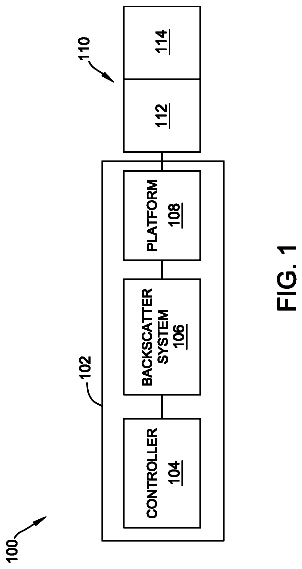
FIG. 1 provides an illustration of the overall ROV dredging process.
FIG. 2A provides an illustration of an ROV and its constituent components.
FIG. 2B shows an assembled ROV.
FIG. 3A provides an illustration of a U-bend pipe.
FIG. 3B provides an illustration of the opened U-bend pipe.
FIG. 4A provides an illustration of two rods with different sized spacing between conductive electrodes for determining the presence of a material of interest.
FIG. 4B shows an embodiment where the rods of FIG. 4A are incorporated in-line into a pipe.
FIG. 4C shows an embodiment of a stack of electrodes.
FIGS. 4D and 4E show two solid state electrode stacks able to be used in some embodiments of the present invention.
FIGS. 5 to 7 illustrate various embodiments of mining processes that include in-line monitors according to various aspects of the invention.
FIG. 8 shows an ROV mining a face of the alluvial deposit, and backfilling the excavated region.
Detailed description of the embodiments
The invention relates to the extraction of minerals from alluvial deposits that are located underground, beneath a rock layer. Alluvial material or alluvial deposits includes loose, unconsolidated soil or sediments of which clay, gravel, sand, and/or silt are examples. The rock layer may for example be a layer of basalt that has formed from volcanic activity where basaltic lava has flowed over an area containing an alluvial mineral deposit, and has cooled and solidified over the top of the alluvial mineral deposit. The alluvial mineral deposits beneath this rock layer may contain a number of valuable minerals, such as gold. However, as the alluvial deposits are trapped beneath a rock layer, they are difficult to access and extract. Furthermore, the alluvial deposits may be located below the water table, so any excavation of the alluvial deposits can lead to the excavated region filling with water.
The description continues in the full USPTO document.
 Lapsed, fee not paid11 drawings

