Cross reference to related applications
This application is the U.S. National Stage entry of International Application Number PCT/JP2014/006260 filed under the Patent Cooperation Treaty having a filing date of Dec. 16, 2014, which, in turn, claims priority to Japanese Patent Application Serial Number 2013-271959 having a filing date of Dec. 27, 2013, the disclosures of both of which are hereby incorporated by reference herein in their entirety for all purposes.
Technical field
The present invention relates to a vehicle seat that can change to a tip up condition where the seat cushion is raised to an uppermost position and to a dive down condition where the seat back is tilted forward with the seat kept in the same configuration in relation to the seat back.
Background art
In recent years, vehicle seats such as those for automobiles are fitted with various mechanisms and devices for selectively changing the configuration of the seat in various different ways. For instance, a seat back is pivotally attached to a high level part of the floor, and a seat cushion is pivotally attached to the seat back so as to be selectively tilted upward. With the seat cushion kept tilted up onto the seat back, the seat back may be tilted forward (toward the seat cushion).
In such a seat that can selectively change the configuration, the seat cushion can be fixed in the tip up position where the seat cushion is raised to the uppermost position so that the process of stowing the luggage in the created space may be simplified. However, to put the forwardly tilted seat back back to the use position, an operation to release the lock of the tip up lock mechanism is required. To overcome this problem, it is known to provide a lock release mechanism that automatically disables the lock by the tip up lock mechanism when the seat back is tilted forward. See Patent Document 1.
This lock release mechanism consists of a release cam pivotally attached to the cushion frame so as to be rotatable in the direction to engage the lock plate of the tip up lock mechanism and a lock release cable for rotating the release cam. The lock release cable includes a cable and an outer tube encasing the cable. One end of the cable is connected to the release cam, and the corresponding end of the outer tube is fixed to a part of the cushion frame adjoining the release cam. The other end of the cable is connected to a floor hinge that pivotally supports the seat back on the floor, and the corresponding end of the outer tube is fixed to a fixing member attached to an outer side of the lower back (back hinge) of the seat back frame. Thereby, when the seat back is tilted forward, the length of the cable extending between the floor hinge and the fixing part increases on the other end side of the cable so that the cable is pulled on the one end side thereof to rotate the release cam, thereby restricting the rotation (the locking action) of the lock plate. PRIOR ART DOCUMENT(S) Patent Document(s)
Patent Document 1: JP4263628B SUMMARY OF THE INVENTION Task to be Accomplished by the Invention
However, according to the seat proposed in Patent Document 1, because the fixing part for fixing the other end of the outer tube of the cable for the lock release mechanism is provided on the outer side of the back frame, a gap is required between the back frame and the cushion frame for placing the fixing part therein so that the lateral dimension of the seat had to be increased.
In view of such a problem of the prior art, a primary object of the present invention is to prevent the increase in the lateral dimension of a vehicle seat equipped with a tip up lock cancel mechanism. Means for Accomplishing the Task
To achieve such an object, the present invention provides a vehicle seat comprising a seat back (S 2 ) pivotally attached to a seat base ( 26 ), a seat cushion (S 1 ) attached to the seat back in a rotatable manner relative to the seat back between a seating position and a tip up position tilted upward toward the seat back, a tip up mechanism ( 5 ) for retaining the seat cushion at least in the tip up position and a tip up lock cancel mechanism ( 113 ) for releasing the seat cushion from a retained condition effected by the tip up mechanism in response to a forward tilting movement of the seat back, wherein: the seat back includes a pair of back side frames ( 46 ) extending downward and connected to the seat base; and the tip up lock cancel mechanism includes a cable encasing member ( 109 ) having one end fixed to the seat cushion and another end fixed to one of the back side frames via a fixing part ( 112 ), and a cable ( 107 ) slidably received in the cable encasing member and having one end connected to the tip up mechanism and another end connected to the seat base, the fixing part ( 112 ) for fixing the cable encasing member to the back side frame being located on an inner side of the back side frame.
According to this arrangement, because the fixing part that fixes the cable encasing member to the back side frame is attached to the inner side of the back side frame, the gap between the back side frame and the cushion frame can be minimized, and the lateral dimension of the seat is not required to be increased.
In this invention, preferably, the seat back further includes a seat back frame ( 45 ) formed by connecting an upper member, a pair of side members and a lower member with one another, and the fixing part is located lower than the lower member when the seat back is in the use position.
According to this arrangement, because the fixing part is positioned in such a manner that the fixing part does not obstruct the changing of the configuration of the seat, an efficient space utilization can be achieved, and the lateral dimension of the seat is not required to be increased.
In this invention, the seat back may include a seat back frame ( 45 ) made of pipe material and a reinforcement member ( 47 ) extending between the seat back frame and each back side frame, and the fixing part is integrally formed with the reinforce member.
Because the fixing part is integrally formed with the reinforce member, no extra component is required for the fixing part, and the number of component parts and the amount of assembly work can be reduced.
In this invention, preferably, the back side frame corresponding to the fixing part is provided on an outer side of the seat base, and the fixing part projects inwardly of the seat in a position laterally corresponding to the seat base, and is configured to restrict a rearward tilting of the seat back by engaging the seat base.
According to this arrangement, because the fixing part can function as a stopper for limiting the rearward tilting movement of the seat back, no separate component is required for the stopper, and the number of component parts and the amount of assembly work can be reduced.
In this invention, preferably, the seat cushion includes a pair of cushion side frames ( 85 ) pivotally attached to the seat back at respective base ends thereof, the tip up mechanism being attached to an outer side of one of the cushion side frames, and the seat back further includes a support member ( 89 ) attached to a fastening seat ( 88 ) formed on an outer side of the corresponding back side frame and having a lower free end rotatably supporting the seat cushion, a recess ( 90 ) for passing the cable encasing member in a fore and aft direction when the seat back is in the use position being formed in an outer side part of the back side frame located below the fastening seat.
According to this arrangement, the cable encasing member is passed through a part located a laterally inside of the connecting portion between the cushion side frame and the support member, and adjacent to the connecting portion, without interfering with the tip up mechanism. Therefore, the cable encasing member can be positioned in a part which moves very little when the seat cushion is rotated.
In this invention, the base end of each cushion side frame may be positioned between the corresponding support member and the back side frame.
According to this arrangement, the dimension of the tip up mechanism provided on the outer side of the cushion side frame protruding in the lateral direction from the support member can be minimized, and the lateral dimension of the seat is not required to be increased.
The vehicle seat of the present invention may further comprise a slide mechanism for permitting the seat base to slide in the fore and aft direction and selectively fixing the seat base at a selected fore and aft position. Preferably, the slide mechanism includes a slide lock cancel cable ( 31 ) for releasing a lock of a slide position of the seat base, and the slide lock cancel cable is passed through the recess.
According to this arrangement, the cable encasing member is passed through a part located a laterally inside of the connecting portion between the cushion side frame and the support member, and adjacent to the connecting portion. Therefore, the cable encasing member can be positioned in a part which does not interfere with the tip up mechanism and moves very little when the seat cushion is rotated. Effect of the Invention
According to such arrangements, even when equipped with a tip up lock cancel mechanism, the lateral dimension of the seat is not required to be increased.
Brief description of the drawing(s)
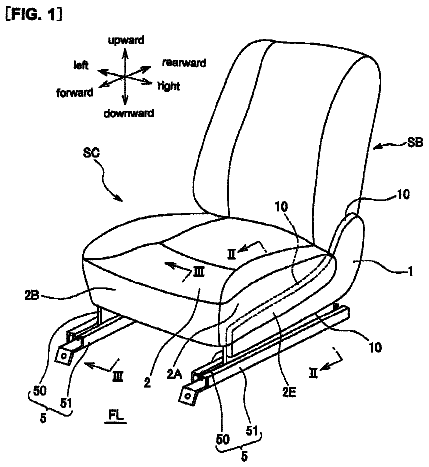
FIG. 1 is a perspective view of a vehicle seat embodying the present invention;
FIG. 2 is a perspective view of the seat frame of the vehicle seat;
FIG. 3 is a right side view of the seat frame of the vehicle seat;
FIG. 4 is a plan view of the base frame of the vehicle seat;
FIG. 5 is a plan view of the seat frame of the vehicle seat;
FIG. 6 is a rear view of the seat frame of the vehicle seat;
FIG. 7 is a perspective view of the seat frame of the vehicle seat as seen from a lower front direction;
FIG. 8 is a fragmentary sectional view of the stand base;
FIG. 9 is a fragmentary view of the reclining mechanism;
FIG. 10 is a fragmentary view of the tip up mechanism;
FIG. 11 is an exploded perspective view of the ottoman;
FIG. 12 is a fragmentary view of the angle adjustment mechanism of the ottoman;
FIG. 13 is a fragmentary view of the detent mechanism of the ottoman;
FIG. 14 are diagrams illustrating the mode of operation of the vehicle seat; and
FIG. 15 are further diagrams illustrating the mode of operation of the vehicle seat.
Description of the preferred embodiment(s)
A preferred embodiment of the present invention is described in the following with reference to the appended drawings. In the following description, the directions are based on the view of the person seated in the seat S. The directions associated with various parts of the seat S are based on the seat S in the state suitable for seating an occupant. Those component parts that are provided in pairs on either side are denoted with common numerals, and may be referred to as being on the left or on the right as required.
(Overall Structure)
As shown in FIG. 1 , the vehicle seat S is used as a rear seat (of a second row or a third row) of an automobile, and includes a seat cushion S 1 , a seat back S 2 , a head rest S 3 and an ottoman (leg rest) S 4 . In some cases, only the component parts on one side of the seat are described as the seat is generally symmetric with respect to a center line extending in the longitudinal direction.
Referring to FIG. 2 also, the seat cushion S 1 , the seat back S 2 , the head rest S 3 and the ottoman S 4 are internally provided with a seat frame F. The seat frame F includes a cushion frame F 1 forming a frame for the seat cushion S 1 , a back frame F 2 forming a frame for the seat back S 2 , a head rest frame F 3 forming a frame for the head rest S 3 , and an ottoman frame F 4 forming a frame for the ottoman S 4 .
The seating side of the cushion frame F 1 , the back resting side of the back frame F 2 , the head supporting side of the head rest frame F 3 and the leg supporting side of the ottoman frame F 4 are fitted with a seat cushion pad P 1 , a seat back pad P 2 , a head rest pad P 3 and the ottoman pad P 4 , respectively, and each pad is made of cushion material such as polyurethane foam and covered by a skin member SK. The skin member SK is made of sheet material such as synthetic leather and fabric. The bottom side of the cushion frame F 1 , the back side of the back frame F 2 and the reverse side of the ottoman frame F 4 are fitted with respective covers made of plastic material, and the bottom surface, the back surface and the reverse surface of these frames may be defined by these covers.
The back frame F 2 is attached to a floor 4 of the vehicle via a slide mechanism 2 and a reclining mechanism 3 so that the back frame F 2 is slidable with respect to the floor 4 , and rotatable (tiltable) with respect to the slide mechanism 2 . The cushion frame F is rotatably attached to the back frame F 2 via a tip up mechanism 5 . The head rest frame F 3 is slidably attached to the back frame F 2 . The ottoman frame F 4 is slidably attached to the cushion frame F 1 . The ottoman frame F 4 is provided with an angle adjustment mechanism 6 so as to be tiltable.
As shown in FIG. 3 , the floor 4 includes a high level part 11 having the slide mechanism 2 attached thereto and a low level part 12 located in front of the high level part 11 at a lower level. An upright wall 13 is provided between the high level part 11 and the low level part 12 as a transitional part. The floor 4 is covered by an upholstery material such as unwoven fabric made by needle punching, for instance. The low level part 12 of the floor 4 is covered by a floor mat which may be laid over the upholstery material.
As shown in FIGS. 4 to 7 , the slide mechanism 2 includes a pair of slide mechanism parts positioned on either side of the seat S, and each slide mechanism part includes a low er rail 15 , an upper rail 16 slidably mounted on the lower rail 15 and a rail lock member 17 for fixedly securing the upper rail 16 on the lower rail 15 . The slide mechanism 2 may consist of any per se known type. The lower rails 15 extend in the fore and aft direction laterally spaced from each other on the high level part 11 ( FIG. 3 ) of the floor 4 . Each lower rail 15 is attached to the floor 4 by using screws or the like. Each upper rail 16 is engaged by the corresponding lower rail 15 in a slidable manner in the fore and aft direction. Only one of the slide mechanism parts is described in the following description as the two parts are essentially identical to each other.
The lower rail 15 is formed with a plurality of lock holes (not shown in the drawings) arranged in the lengthwise direction. The rail lock member 17 is pivotally attached to the upper rail 16 so as to be engageable with a selected one of the lock holes. The rail lock member 17 prevents the movement of the upper rail 16 and a slide member 21 attached thereto relative to the lower rail 15 . The rail lock member 17 is urged by a biasing means consisting of a spring (not shown in the drawings) into engagement with a selected one of the lock holes. Normally, the rail lock member 17 is kept engage by the lock hole under the biasing force of the spring, and prevents the movement of the slide member 21 . When the rail lock member 17 is pivoted by the operation of a vehicle occupant against the biasing force of the spring, the rail lock member 17 is disengaged from the lock hole, and the upper rail 16 is rendered moveable.
The slide member 21 which is attached to the upper rail 16 is made by welding a plurality of stamp formed sheet metal pieces together. The slide member 21 extends along the length of the upper rail 16 . The two slide members 21 are connected to each other by a slider front member 23 at the front ends, by a slider rear member 24 at the rear ends, and by a slider middle member 25 at the middle parts. These cross members 23 , 24 and 25 are made of metallic pipe stock, and are connected to the slide members 21 by welding or by using screws, and extend laterally parallel to one another. Thus, the slide members 21 and the cross members 23 , 24 and 25 jointly form a frame structure serving as a seat base 26 . The seat base 26 and the two upper rails 16 are thus designed to move in the fore and aft direction as a single body.
The right and left rail lock members 17 are connected to each other via a link mechanism 28 ( FIGS. 4 to 6 ). The link mechanism 28 can change between a locked condition and a released condition, and is normally placed in the locked condition under the biasing force of the spring urging the rail lock members 17 . In the locked condition, the link mechanism 28 permits the engagement of the rail lock member 17 with the selected lock hole. When the link mechanism 28 is changed from the locked condition to the released condition by the operation of the vehicle occupant, the link mechanism 28 keeps the rail lock member 17 disengaged from the lock hole against the biasing force of the spring. As will be described hereinafter, an end of a first rail cable 31 and an end of a second rail cable 32 are connected to the link mechanism 28 for transmitting force thereto. The link mechanism 28 is disengaged when at least one of the first rail cable 31 and the second rail cable 32 is pulled.
As shown in FIGS. 4 and 8 , a stand base 34 is placed across the slider front member 23 and the slider middle member 25 . The stand base 34 is made by stamp forming sheet metal, and is welded to a laterally middle part of the slider front member 23 at the front end and to a laterally middle part of the slider middle member 25 at the rear end. A support groove 35 extends laterally on the upper side of the stand base 34 over the entire width of the stand base 34 . The support groove 35 opens out in an upper and forward direction for supporting a stand leg 37 which will be described hereinafter.
The stand base 34 is provided with a pivotable engagement claw 41 having a rotational center line extending in parallel with the (laterally extending) axial line of the support groove 35 , and can take a projecting position projecting from a side of the support groove 35 into the support groove 35 as shown by the solid lines in FIG. 8 and a retracted position cleared from the support groove 35 as shown by the imaginary lines in FIG. 8 . A torsion spring 42 is interposed between the stand base 34 and the engagement claw 41 to urge the engagement claw 41 into the projecting position. In the projecting position, the engagement claw 41 engages a cross member 94 of the stand leg 37 to prevent the cross member 94 from leaving the support groove 35 . The outer side of the engagement claw 41 or the side of the engagement claw 41 facing the open side of the support groove 35 when the engagement claw 41 is in the projecting position is formed as an inclined surface.
As will be discussed hereinafter, an end of an engagement claw cable 43 is connected to the engagement claw 41 to transmit force thereto. By pulling the engagement claw cable 43 , the engagement claw 41 is caused to pivot from the projecting position to the retracted position.
As shown in FIGS. 2, 5 and 6 , the back frame F 2 includes a pipe frame 45 formed as an elongated rectangular frame and a pair of back side frames 46 welded to either vertically extending lower side part of the pipe frame 45 . The back side frames 46 are formed by stamp forming sheet metal. Each back side frame 46 is provided with a concave surface surrounding the outer side surface of the lower part of the corresponding side part of the pipe frame 45 . The lower part of each back side frame 46 extends downward beyond the corresponding side part of the pipe frame 45 . A part of each back side frame 46 extends to a lower part of the pipe frame 45 , and is welded thereto. A reinforcement plate 47 extends across each back side frame 46 and the adjoining lower part of the pipe frame 45 , and welded to these components for the reinforcement of the back frame F 2 . The upper part of each reinforcement plate 47 forms a hollow, three-dimensional structure in cooperation with the corresponding back side frame 46 and the pipe frame 45 , and the lower part thereof extends downward along the corresponding back side frame 46 .
Each back side frame 46 defines a pair of side surfaces facing either lateral direction. The left side surface of the lower part of the left back side frame 46 opposes the right side surface of the left slide member 21 , and is connected thereto in a rotatable manner. As shown in FIGS. 5 to 7 , the left side surface of the lower part of the right back side frame 46 opposes the right side surface of the reclining mechanism 3 attached to the right slide member 21 , and is connected to the right slide member 21 in a rotatable manner, via the reclining mechanism 3 . The rotational center lines of the right and left back side frames 46 are coaxially disposed.
The reclining mechanism 3 is configured to keep the rotational (tilting) angle of the right back side frame 46 relative to the right slide member 21 at a selected angle. The reclining mechanism 3 is provided with a release lever 51 ( FIG. 7 ) that can be operated to change the rotational angle of the right back side frame 46 relative to the right slide member 21 . The reclining mechanism 3 may consist of any per se known mechanism.
As shown in FIG. 9 , the reclining mechanism 3 used in the illustrated embodiment includes a lower plate 52 attached to the right slide member 21 , an upper plate 53 attached to a lower part of the right side frame opposite to the lower plate 52 so as to be rotatable relative to the lower plate 52 , a connecting shaft 54 passed through the rotational centers of the lower plate 52 and the upper plate 53 , a cam plate 55 positioned in an inner space defined between the upper plate 53 and the lower plate 52 and rotationally fast with the connecting shaft 54 , a plurality of lock members 56 positioned in the inner space and a torsion spring 57 urging the cam plate 55 in a rotational direction. The lock members 56 are engaged by respective guide grooves 58 formed in the lower plate 52 so as to be movable in the radial direction of the lower plate 52 . Each lock member 56 is provided with a cam in the radially inner end thereof and external teeth 59 in the radially outer end thereof, the external teeth 59 engaging internal teeth 61 formed on the inner peripheral part of the upper plate 53 (defining the inner space) when the lock member 56 is displaced to the radially outer position thereof. The cam plate 55 engages the cam followers of the lock members 56 such that the lock members 56 are displaced radially outward when the cam plate 55 is turned in one direction, and the lock members 56 are displaced radially inward when the cam plate 55 is turned in the other direction. An end of the connecting shaft 54 is passed through the upper plate 53 and the right back side frame 46 , and is connected to the radially extending release lever 51 ( FIGS. 3 and 7 ) at the terminal end of the connecting shaft 54 .
In the reclining mechanism 3 , normally, the cam plate 55 is urged in the one rotational direction by the torsion spring 57 so that the lock member 56 is displaced to the radially outward position, and the external teeth 59 of the lock members 56 engage the internal teeth 61 of the upper plate 53 . As a result, the lock member 56 prevents the relative rotation between the lower plate 52 and the upper plate 53 . In other words, the reclining mechanism 3 is normally placed under a locked condition where the relative rotation between the lower plate 52 and the upper plate 53 is prohibited owing to the biasing force of the torsion spring 57 . When the release lever 51 is turned in the release direction by the vehicle operator so that the connecting shaft 54 and the cam plate 55 are turned in the other direction against the biasing force of the torsion spring 57 , the lock member 56 is displaced to the radially inward position, and the external teeth 59 of the lock member 56 are disengaged from the internal teeth 61 of the upper plate 53 . As a result, the relative rotation between the lower plate 52 and the upper plate 53 is enabled. An end of a reclining cable 63 ( FIGS. 3 and 7 ) is connected to the release lever 51 for transmitting the operating force. When the reclining cable 63 is pulled, the release lever 51 rotates in the release direction.
As shown in FIGS. 2, 3 and 5 , a bracket 66 for supporting a handle unit 65 is attached to the upper end of the right side part of the pipe frame 45 by welding. The handle unit 65 includes a case 67 with an upwardly and rearwardly facing opening and a handle 68 pivotally attached to the case 67 therein. As shown in FIGS. 1 and 2 , the part of the seat back pad P 2 corresponding to the handle unit 65 and the corresponding part of the skin member SK are removed so that the handle 68 may be exposed in the upper right part of the seat back S 2 for a vehicle occupant to operate.
The handle 68 is connected to an end of the engagement claw cable 43 whose other end is connected to the engagement claw 41 ( FIG. 8 ) and an end of the reclining cable 63 whose other end is connected to the release lever 51 ( FIG. 3 ). The engagement claw cable 43 and the reclining cable 63 are encased in respective outer tubes 71 , 72 in a slidable manner. Referring to FIG. 5 , although not shown in any great detail, an end of the engagement claw outer tube 71 encasing the engagement claw cable 43 is attached to the stand base 34 , and extends along the right slide member 21 and upward along the right back side frame 46 and the right side part of the pipe frame 45 before being attached to the bracket 66 at the other end. As shown in FIG. 3 , an end of the reclining outer tube 72 encasing the reclining cable 63 is attached to the right side surface of the right back side frame 46 , and extends upward along the right back side frame 46 and the right side part of the pipe frame 45 before being attached to the bracket 66 at the other end. The engagement claw outer tube 71 and the reclining outer tube 72 are bundled together by a band tie, and attached to the right side part of the pipe frame 45 .
When the vehicle occupant pulls the handle 68 to cause the handle 68 to tilt in a prescribed direction, the engagement claw cable 43 is pulled toward the handle 68 so that the engagement claw 41 ( FIG. 8 ) rotates from the projecting position to the retracted position, and the engagement claw 41 that locks the stand leg 37 is released. At the same time, the reclining cable 63 is pulled toward the handle 68 so that the release lever 51 is tilted in the release direction, and the lock on the reclining mechanism 3 is released.
As shown in FIGS. 2 and 3 , an armrest bracket 76 for supporting an armrest 75 is attached to the left side part of the pipe frame 45 by welding. The armrest bracket 76 projects forward from the left side part of the pipe frame 45 . The armrest 75 is attached to the armrest bracket 76 so as to be rotatable within a prescribed angular range.
As shown in FIGS. 2 and 5 , a pair of head rest retaining portions 78 for supporting the head rest S 3 are attached to the upper end part of the pipe frame 45 . Each head rest retaining portion 78 consists of a tubular member which receives a support 79 consisting of a tubular member made of plastic material. The head rest S 3 is mounted on the top end part of the pipe frame 45 via a pair of head rest pillars 80 included in the head rest frame F 3 which are inserted in the respective supports 79 of the head rest retaining portion 78 .
A plurality of auxiliary frames 82 each consisting of a metallic rod member are attached to respective suitable parts of the pipe frame 45 . The auxiliary frames 82 include those extending between the right and left side parts of the pipe frame 45 and those extending rightward and leftward from the right and left side parts of the pipe frame 45 , respectively. The auxiliary frames 82 fill the gaps in the pipe frame 45 so that the seat back pad P 2 may be supported in a stable manner.
As shown in FIGS. 2 and 5 , the cushion frame F 1 includes a pair of cushion side frames 85 extending in the fore and aft direction along either side of the cushion frame F 1 , a cushion front member 86 connected between the front ends of the cushion side frames 85 , and a cushion rear member 87 connected between the rear ends of the cushion side frames 85 . Each cushion side frame 85 is made by stamp forming sheet metal, and has a major plane facing in the lateral direction. The peripheral part of each cushion side frame 85 is bent in the outboard direction. While the front end of each cushion side frame 85 extends in the fore and aft direction, the rear end of each cushion side frame 85 is bent upward and rearward relative to the front part. The cushion rear member 87 is attached to the bent part of the corresponding cushion side frame 85 .
The rear end part of the left cushion side frame 85 is rotatably attached to the left back side frame 46 such that the right side surface of the left cushion side frame 85 opposes the upper part of the left side surface of the left back side frame 46 .
As shown in FIG. 6 , a fastening seat 88 is formed in an upper part of the right back side frame 46 . The fastening seat 88 projects rightward, and defines a flat projecting end. A support plate 89 is attached to the fastening seat 88 by using threaded bolts. A part of the right back side frame 46 immediately below the fastening seat 88 is provided with a recess 90 , and a gap is defined between the recess 90 and the support plate 89 . The support plate 89 is a vertically extending metallic plate having a laterally directed major plane, and is attached to the fastening seat 88 at the upper end thereof. The lower part of the support plate 89 is spaced from the right side surface of the right back side frame 46 . The rear end of the right cushion side frame 85 is positioned between the right back side frame 46 and the support plate 89 , and is attached to the support plate 89 in a rotatable manner. The rotational center lines of the right and left cushion frames F 1 extend laterally in a coaxial relationship.
Referring to FIGS. 2 and 5 once again, a center support member 91 extending in the fore and aft direction is connected between the cushion front member 86 and the cushion rear member 87 . The center support member 91 supports the seat cushion pad P 1 and the hip of the vehicle occupant from below in the central part of the cushion frame F 1 , and is preferably provided with a resiliency. In the illustrated embodiment, the center support member 91 consists of a plate member (center plate) formed by stamp formed sheet metal, and is provided with a vertically facing major plane. The front end of the center support member 91 is welded to the laterally central part of the cushion front member 86 , and the rear end thereof is welded to the laterally central part of the cushion rear member 87 . The lateral width of the center support member 91 is about one third (⅓) of that of the cushion front member 86 . The center support member 91 may be provided with beads for reinforcement and openings for reducing the weight. Alternatively, the center support member 91 may be made of elastic members such as wire spring, and may be provided in a plurality of locations along the lateral direction.
As shown in FIG. 7 also, the stand leg 37 is pivotally attached to the two cushion side frames 85 . The stand leg 37 includes a pair of arms 93 each having a base end pivotally attached to the corresponding cushion side frame 85 and a cross member 94 connected between the other ends of the arms 93 so that the stand leg 37 is provided with the shape of letter U. The most part of the arms 93 and the cross member 94 are made by bending a metallic pipe in the shape of letter U. The one end of each arm 93 is formed by a bracket welded to the metallic pipe. In side view ( FIG. 3 ), the stand leg 37 is pivotable between a retracted position where the cross member 94 adjoins the lower surface of the center support member 91 and the arms 93 extend along the respective cushion side frames 85 as shown by the imaginary lines and a use position or a deployed position where the arms 93 project downward from the respective cushion side frames 85 as shown by the solid lines. In either position, the stand leg 37 is located on the outside of the cover defining the bottom surface of the seat cushion S 1 .
When the stand leg 37 is in the use position, the stand leg 37 can fit into the support groove 35 of the stand base 34 . When the stand leg 37 is engaged by the support groove 35 , the seat cushion S 1 is retained by the stand leg 37 from below, and is kept in the seating position where the seat surface (upper surface) thereof extends substantially horizontally. When engaged by the support groove 35 , the stand leg 37 is prevented from pivoting from the use position to the retracted position. In other words, by being engaged by the support groove 35 , the angular position of the seat cushion S 1 relative to the seat back S 2 is determined.
When inserting the cross member 94 of the stand leg 37 into the support groove 35 , the cross member 94 is pushed against the inclined surface of the engagement claw 41 to cause the engagement claw 41 to rotate from the projecting position to the retracted position against the biasing force of the torsion spring 42 . Once the cross member 94 is forced into the support groove 35 , the engagement claw 41 rotates back into the projecting position under the biasing force of the torsion spring 42 . When placed in the projecting position, the engagement claw 41 engages the cross member 94 , and prevents the cross member from being detached from the support groove 35 . When the cross member 94 is desired to be disengaged from the support groove 35 , the vehicle occupant operates the handle 68 ( FIG. 1 ), and displaces the engagement claw 41 to the retracted position via the engagement claw cable 43 .
As shown in FIGS. 3, 5 and 6 , the tip up mechanism 5 is interposed between the right cushion side frame 85 and the support plate 89 . The tip up mechanism 5 fixedly secures the right cushion side frame 85 to the support plate 89 to fix the angular position of the seat cushion S 1 relative to the seat back S 2 such that the seat cushion S 1 is tilted upward from the seating position. The tip up mechanism 5 may consist of any per se known mechanism.
As shown in FIG. 10 , the tip up mechanism 5 of the illustrated embodiment includes a plurality of engagement notches 101 formed in the lower edge of the support plate 89 , a lock member 102 pivotally attached to the right side surface of the right cushion side frame 85 and moveable between an engagement position engaging one of the engagement notches 101 indicated by the imaginary lines and a release position disengaged from the engagement notches 101 indicated by the solid lines, a rubber member (not shown in the drawings) urging the lock member 102 to the engagement position, a cam member 103 pivotally attached to the right side surface of the right cushion side frame 85 and configured to pivot between a first position for engaging the lock member 102 to position the lock member 102 in the engagement position as indicated by the solid lines and a second position for disengaging the lock member 102 as indicated by the imaginary lines, and a tension coil spring 104 positioned between the cam member 103 and the right side surface of the right cushion side frame 85 to urge the cam member 103 toward the second position.
The number of the engagement notches 101 may be one or greater. One of the engagement notches 101 is located so as to engage the lock member 102 when the seat cushion S 1 is located in an upper limit position (tip up position) in the angular range of the seat cushion S 1 or when the seat surface (upper surface) of the seat cushion S 1 is closest from the support surface (front surface) of the seat back S 2 . When the seat cushion S 1 is in the tip up position, the front part of the right cushion side frame 85 is substantially in parallel with the right side part of the pipe frame 45 . The remaining engagement notches 101 may be provided in positions for engaging the lock member 102 at various angular positions between the seating position and the tip up position of the seat cushion S 1 . Therefore, owing to the tip up mechanism 5 , when the right cushion side frame 85 is upwardly rotated relative to the support plate 89 , the lock member 102 can engage the corresponding engagement notch 101 under the biasing force of the tension coil spring 104 at the selected angular position.
The engagement notches 101 may be configured such that the engagement with the lock member 102 is maintained when the right cushion side frame 85 is forced in the direction to tilt downward relative to the support plate 89 so as to prevent the rotation of the right cushion side frame 85 relative to the support plate 89 , and the disengagement of the lock member 102 is permitted when the right cushion side frame 85 is forced to tilt upward relative to the support plate 89 so as to permit the rotation of the right cushion side frame 85 relative to the support plate 89 . According to such an arrangement, even after the lock member 102 has been engaged by one of the engagement notches 101 , the upward tiling of the right cushion side frame 85 is permitted. As the right cushion side frame 85 is further tilted upward, the lock member 102 is engaged by the succeeding engagement notch 101 . Therefore, even when the cam member 103 is in the second position indicated by the imaginary lines, the right cushion side frame 85 can be tilted upward to a desired angle.
When the cam member 103 is angularly displaced by the operation of the vehicle occupant to the first position indicated by the solid lines against the biasing force of the tension coil spring 104 , the lock member 102 moves to the release position, and is prevented from being engaged by the engagement notches 101 . An end of a first tip up cable 106 and an end of a second tip up cable 107 are connected to the cam member 103 for transmitting force. The first tip up cable 106 in encased in a first tip up outer tube 108 , and the second tip up cable 107 is encased in a second tip up outer tube 109 , each in a slidable manner.
The description continues in the full USPTO document.
 Lapsed, fee not paid4 drawings